Table of Contents
Advertisement
Quick Links
Advertisement
Table of Contents

Subscribe to Our Youtube Channel
Related Manuals for THORLABS ODL100-FS


Summary of Contents for THORLABS ODL100-FS
- Page 1 ODL100-FS(/M) Optical Delay Line User Guide...
-
Page 2: Table Of Contents
Setup and Alignment ......................6 Chapter 5 Software Package ......................9 Chapter 6 Specifications ........................13 Chapter 7 Regulatory ........................14 7.1. Waste Treatment is Your Own Responsibility ............14 7.2. Ecological Background ....................14 Chapter 8 Thorlabs Worldwide Contacts ..................15... -
Page 3: Chapter 1 Warning Symbol Definitions
Optical Delay Line Chapter 1: Warning Symbol Definitions Chapter 1 Warning Symbol Definitions Below is a list of warning symbols you may encounter in this manual or on your device. Symbol Description Direct Current Alternating Current Both Direct and Alternating Current Earth Ground Terminal Protective Conductor Terminal Frame or Chassis Terminal... -
Page 4: Chapter 2 Safety
Optical Delay Line Chapter 2: Safety Chapter 2 Safety All statements regarding safety of operation and technical data in this instruction manual will only apply when the unit is operated correctly. WARNING This unit must not be operated in explosive environments. CAUTION Only apply a small clamping force when tightening the screws that hold the right-angle prism mirror. -
Page 5: Chapter 3 Introduction
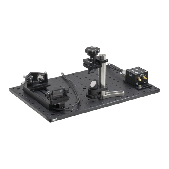
Chapter 3 Introduction Thorlabs’ ODL100-FS(/M) Free-Space Optical Delay Line Kit offers customers a tested set of Thorlabs components to build an optical delay line. The kit is based on our DDSM100(/M) long-travel, low-profile direct drive stage, and is capable of tuning the optical delay up to 666.6 ps. Repeatable delay shifts down to 3.3 femtoseconds are achievable. -
Page 6: Chapter 4 Setup And Alignment
Optical Delay Line Chapter 4: Setup and Alignment Chapter 4 Setup and Alignment WARNING Infrared laser beams are particularly dangerous because they cannot be seen. Always wear appropriate laser safety glasses (not included) when working with laser beams. The kit includes a DDSM100(/M) Linear Direct Drive Stage, an RS99(/M) Periscope Assembly, a V-block with two pairs of built-in kinematic adjusters, two MH25 Mirror Holders for attaching mirrors to the V-block, two SM05D5D Ring-Actuated Irises, two removable FT-SM05 Mounting Bases for attaching the irises to the V-block, four Ø1”... - Page 7 Optical Delay Line Chapter 4: Setup and Alignment Periscope Assembly 1. Attach the top and bottom unit of the periscope to the Ø1” pillar post. The pieces tighten against the post using brass-tipped 1/4"-20 (M6) setscrews. 2. Install the Ø1” mirrors into the periscope. They are each secured by a nylon-tipped 8-32 (M4) setscrew. 3.
- Page 8 1. Connect the DDSMA1 mounting plate to the DDSM100(/M) delay stage. It attaches using two M3 cap screws (included). The same mounting plate is used for ODL100-FS and ODL100-FS/M. The adapter needs to be mounted on the side where the drive cables exit the stage.
-
Page 9: Chapter 5 Software Package
We have implemented a GUI for the ODL100-FS to read the current stage position; control the stage position, speed, and acceleration; and execute scan sequences. With this software, it is possible to precisely choose the optical delay you wish to add or subtract from your beam path. - Page 10 Optical Delay Line Chapter 5: Software Package Figure 4 Operational Panel To adjust the delay, simply use the slider arrows or type in the desired delay in millimeters (from 0 – 100 mm) or in picoseconds (from 0 ps to 666.6 ps) in the Manual Move Panel. You may also right-click on the slider bar to bring up the screen shown in Figure 6 shown on Page 11.
- Page 11 Optical Delay Line Chapter 5: Software Package Figure 5 Controller Panel Acceleration – Sets the acceleration of the translating plate in units of millimeters per second, per • second. Delay Operation Delay Slider – Moves the stage in units of either millimeters or picoseconds, using either arrow to •...
- Page 12 Optical Delay Line Chapter 5: Software Package Delay Scan Scans can be initiated over a user-defined range from the current stage position. The stage is moved in incremental, user-defined steps, measuring the response as a function of delay. Below are shown the user- configurable delay scan parameters.
-
Page 13: Chapter 6 Specifications
Optical Delay Line Chapter 6: Specifications Chapter 6 Specifications ODL100-FS Specifications Maximum Optical Delay 666.6 ps Delay Sensitivity 3.3 fs Input Beam Height 2.4" – 6" (60 mm – 152 mm) (Adjustable Using Periscope) Output Beam Height 2.4" (60 mm) Based on the minimum repeatable incremental motion of the stage. -
Page 14: Chapter 7 Regulatory
Waste Treatment is Your Own Responsibility If you do not return an “end of life” unit to Thorlabs, you must hand it to a company specialized in waste recovery. Do not dispose of the unit in a litter bin or at a public waste disposal site. -
Page 15: Chapter 8 Thorlabs Worldwide Contacts
Optical Delay Line Chapter 8: Thorlabs Worldwide Contacts Chapter 8 Thorlabs Worldwide Contacts For technical support or sales inquiries, please visit us at www.thorlabs.com/contact for our most up-to- date contact information. USA, Canada, and South America UK and Ireland Thorlabs, Inc. - Page 16 www.thorlabs.com...
Need help?
Do you have a question about the ODL100-FS and is the answer not in the manual?
Questions and answers