Table of Contents
Advertisement
Quick Links
Advertisement
Table of Contents

Subscribe to Our Youtube Channel
Related Manuals for THORLABS OTM211


Summary of Contents for THORLABS OTM211
- Page 1 OTM211 Optical Tweezer System User Guide...
-
Page 2: Table Of Contents
7.1. Laser Specifications ..................... 15 7.2. Power Requirements ..................... 15 7.3. Dimensions and Weights ....................15 Chapter 8 Regulatory ...........................16 8.1. Waste Treatment is Your Own Responsibility ............16 8.2. Ecological Background ....................16 Thorlabs Worldwide Contacts ..................17 Chapter 9 ... -
Page 3: Chapter 1 Warning Symbol Definitions
OTM211 Chapter 1: Warning Symbol Definitions Chapter 1 Warning Symbol Definitions Below is a list of warning symbols you may encounter in this manual or on your device. Symbol Description Direct Current Alternating Current Both Direct and Alternating Current Earth Ground Terminal... -
Page 4: Chapter 2 Safety
Ensure that the line voltage switch is set correctly for your local supply and that the appropriate fuses are installed. Fuses should only be changed by qualified service personnel. The OTM211 contains no user-serviceable parts. Do not operate without cover installed. Refer all maintenance to suitably qualified personnel. -
Page 5: Chapter 3 Description
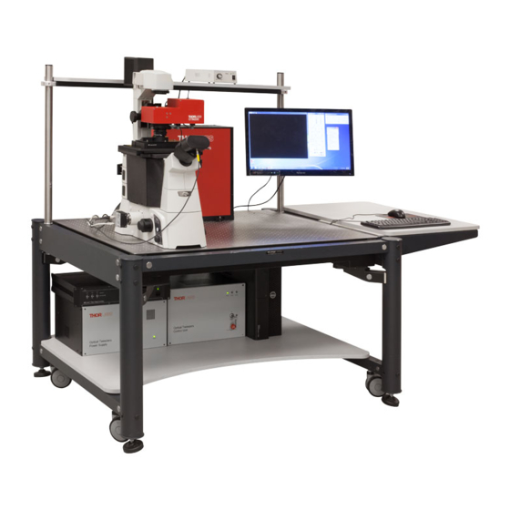
3.1. Introduction The Thorlabs OTM211 is an optical tweezers system designed for inverted microscopes. It provides two independent trapping beams that allow the manipulation of nano- and micro particles. Each path can be used to create several additional traps. The system is completely computer controlled and offers a graphical user interface which provides the user with a set of tools for the most common trapping experiments. -
Page 6: Key System Features
OTM211 Chapter 3: Description The Equipartation method equates the average potential energy of the particle in the trap to the thermal energy of the solvent molecules. In this method, a sample of particle positions is obtained by recording the position detector output over time and converting the voltages to distances using the detector responsivity. -
Page 7: System Components
OTM211 Chapter 3: Description 3.4. System Components The OTM211 includes the following modules: Optics Module 1.3NA Trapping Objective and Condenser 1600 x 1200 CCD Camera with Imaging Adapter Electronics Control Module Power Supply Module Nikon Eclipse Ti-S Inverted Microscope with high resolution XYZ Piezo Stage ... -
Page 8: Optics Module
OTM211 Chapter 3: Description 3.5. Optics Module The optics module includes all the optical and opto-electronic components for creating and controlling multiple optical traps. The conditioned output beam is coupled into the microscope. A schematic for this module is shown below. -
Page 9: Power Supply And Electronic Module
OTM211 Chapter 3: Description 3.6. Power Supply and Electronic Module These two modules provide power and contain the control circuitry for the components in the optics module. The rear panel of the power supply module has connection to the mains power supply and to the electronics module. -
Page 10: Chapter 4 Operation
4.2. Graphical User Interface The OTM211 system comes with a pre-installed software which contains everything needed for system control and data acquisition. In addition an SDK is provided to allow users to easily create applications optimized for their particular requirements. -
Page 11: Sdk
OTM211 GUI Showing Controls 4.3. The OTM211 Tweezers System is supplied with a software development kit (SDK). The SDK gives access to all features of the instrument, thus enabling the creation of custom, application-specific software. The SDK is provided as a 64 Bit Windows dynamic link library (dll). Language bindings for C, National Instruments LabView and C# are available. -
Page 12: Chapter 5 Operating Conditions And Environmental Requirements
Chapter 5: Operating Conditions and Environmental Requirements Chapter 5 Operating Conditions and Environmental Requirements The system will be installed by a member of the Thorlabs team. In preparation for install, the following considerations should be taken into account. 5.1. Selecting a Suitable Operation Environment In order to deliver optimal performance we recommend installing the OTM211 Optical Tweezers System on an actively vibration-damped surface. -
Page 13: Chapter 6 System Connections And Care
OTM211 Chapter 6: System Connections and Care Chapter 6 System Connections and Care 6.1. Module Connections The figure below shows the schematic for the rear panel connections for the optics, electronics, and power supply modules. DC Power Out Max. 300W +/-15VDC Max. -
Page 14: Service
OTM211 Chapter 6: System Connections and Care 6.2. Service Only trained Thorlabs personnel are allowed to open any of the modules to service the system. Please contact Thorlabs Technical Support for more information. 6.3. Accessories and Customization The Thorlabs OTM211 Microscope Tweezers System can be offered in several configurations, e.g. different wavelength, optical power levels, integrated with additional imaging modalities. -
Page 15: Chapter 7 Specifications
OTM211 Chapter 7: Specifications Chapter 7 Specifications 7.1. Laser Specifications Laser Specifications 1064 nm Center Wavelength <0.25 nm Emission Bandwidth (FWHM) Output Power (before split) Panda 980 Fiber Linear Polarization State <0.2% Output Power instabilities (rms) Gaussian, with M <1.1 Output Beam Shape 7.2. -
Page 16: Chapter 8 Regulatory
Waste Treatment is Your Own Responsibility If you do not return an “end of life” unit to Thorlabs, you must hand it to a company specialized in waste recovery. Do not dispose of the unit in a litter bin or at a public waste disposal site. -
Page 17: Chapter 9 Thorlabs Worldwide Contacts
Fax: +46-31-703-40-45 www.thorlabs.de www.thorlabs.com Email: europe@thorlabs.com Email: scandinavia@thorlabs.com France Brazil Thorlabs SAS Thorlabs Vendas de Fotônicos Ltda. 109, rue des Côtes Rua Riachuelo, 171 78600 Maisons-Laffitte São Carlos, SP 13560-110 France Brazil Tel: +33 (0) 970 444 844 Tel: +55-16-3413 7062... - Page 18 www.thorlabs.com...
Need help?
Do you have a question about the OTM211 and is the answer not in the manual?
Questions and answers