Table of Contents
Advertisement
Quick Links
Advertisement
Table of Contents

Related Manuals for THORLABS OTKB-FL


Summary of Contents for THORLABS OTKB-FL
- Page 1 OTKB-FL Optical Trap Kit Fluorescence Modules User Guide...
-
Page 2: Table Of Contents
OTKB-FL ..........................5 Chapter 3 3.1. Introduction ........................5 3.2. Module Weight and Dimensions ..................5 3.3. OTKB-FL design ......................5 3.3.1. Excitation Filter ........................5 3.3.2. Dichroic Mirror ........................5 3.3.3. Emission Filter ........................6 3.4. Connection to OTKB ....................... 7 3.5. -
Page 3: Chapter 1 Warning Symbol Definitions
Optical Trap Kit Fluorescence Light Unit Chapter 1: Warning Symbol Definitions Warning Symbol Definitions Chapter 1 Below is a list of warning symbols you may encounter in this manual or on your device. Symbol Description Direct Current Alternating Current Both Direct and Alternating Current Earth Ground Terminal Protective Conductor Terminal Frame or Chassis Terminal... -
Page 4: Chapter 2 Safety
Optical Trap Kit Fluorescence Light Unit Chapter 2: Safety Safety Chapter 2 All statements regarding safety of operation and technical data in this instruction manual will only apply when the unit is operated correctly. WARNING This unit must not be operated in explosive environments. WARNING Latex gloves should be worn to prevent oil from fingers from reaching all optical surfaces. -
Page 5: Chapter 3 Otkb-Fl
In our modules, we are able to tailor the various filter set suitable to meet your imaging needs. Our OTKB-FL is provided without a light source for users who wish to provide their own light source;... -
Page 6: Emission Filter
Optical Trap Kit Fluorescence Light Unit Chapter 3: OTKB-FL plot (Figure 2 below), the transition wavelength for the fluorescein isothiocyanate (FITC) Dichroic Mirror (MD499) is ~500 nm. Dichroic mirrors are designed to reflect light whose wavelength is below a specific value (i.e. the transition wavelength) while permitting all other wavelengths to pass through it unaltered. -
Page 7: Connection To Otkb
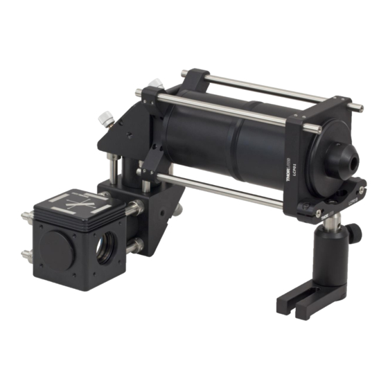
Figure 3 Complete OTKB system with OTKB-FL OTKB-FL is designed to work seamlessly with the OTKB system. The complete assembly is shown in Figure 3. To connect to OTKB, please follow the following instructions: 1. Disconnect the camera segment from the beam expansion segment as shown in Figure 4. -
Page 8: Additional Alignment Tips
Optical Trap Kit Fluorescence Light Unit Chapter 3: OTKB-FL 3. Connect the OTKB-FL segment to the beam expansion segment as shown in the Figure 3. 4. Attach the camera segment onto OTKB-FL as shown in Figure 3. 5. Adjust the TR50 post to keep the collimator segment horizontal. -
Page 9: Chapter 4 Regulatory
Waste Treatment is Your Own Responsibility If you do not return an “end of life” unit to Thorlabs, you must hand it to a company specialized in waste recovery. Do not dispose of the unit in a litter bin or at a public waste disposal site. -
Page 10: Chapter 5 Thorlabs Worldwide Contacts
Optical Trap Kit Fluorescence Light Unit Chapter 5: Thorlabs Worldwide Contacts Thorlabs Worldwide Contacts Chapter 5 USA, Canada, and South America UK and Ireland Thorlabs, Inc. Thorlabs Ltd. 56 Sparta Avenue 1 Saint Thomas Place, Ely Newton, NJ 07860 Cambridgeshire CB7 4EX... - Page 11 www.thorlabs.com...
Need help?
Do you have a question about the OTKB-FL and is the answer not in the manual?
Questions and answers