
Related Manuals for THORLABS OCTG Series


Summary of Contents for THORLABS OCTG Series
- Page 1 OCTG Series, OCT-LKx, and OCT-RAx OCT Standard Scanner, Scan Lens Kit, and Standard Scanner Reference Arm Adapter User Manual...
- Page 2 Original User Manual – not translated...
-
Page 3: Table Of Contents
9.1. Imaging Systems ....................24 9.2. Non-Warranty Repairs ................... 24 9.3. Warranty Exclusions ..................... 24 Chapter 10 Regulatory ........................25 10.1. Waste Treatment is Your Own Responsibility ............. 25 10.2. Ecological Background ..................25 Chapter 11 Thorlabs OCT Support Contact ................26... - Page 4 Chapter 12 Thorlabs Worldwide Contacts .................. 27...
-
Page 5: Chapter 1 Warning Symbol Definitions
OCTG Series Scanner Chapter 1: Warning Symbol Definitions Warning Symbol Definitions Chapter 1 Below is a list of warning symbols you may encounter in this manual or on your device. Symbol Description Direct Current Alternating Current Both Direct and Alternating Current... -
Page 6: Chapter 2 Introduction
WARRANTY WARNING There are sensitive electronic and optical parts in the OCTG. Any modification or servicing of this system by unqualified personnel renders Thorlabs free of any liability. Any modification or the galvanometer scanners or the camera may cause loss of the factory optical alignment. -
Page 7: Care And Maintenance
In order to achieve the intended performance, this scanner should only be used with qualified parts. Please hold a conversation with Thorlabs’ OCT support (see Chapter 11) to determine if other parts you wish to use are compatible. Any modification or servicing of this system by unqualified personnel renders the warranty null and void, leaving Thorlabs free of any liability. -
Page 8: Chapter 3 Scanner Compatibility
OCTG-900; or OCTG-1300 For common statements the abbreviation “OCTG” is used for both setups. The OCTG scanners are fully compatible with all Thorlabs OCT base units of the CALLISTO, VEGA, GANYMEDE, and TELESTO series. The table below gives a short overview of the different standard scanners, their usable wavelength range and lists preferred OCT base units. -
Page 9: Chapter 4 Installation
The OCTG standard scanner is a standalone, preassembled, integrated accessory to an OCT base unit. It should be securely mounted to an optical table or breadboard with minimal vibrations. We recommend mounting the OCTG to a Thorlabs OCT-Stand. 4.1. OCTG Mounting To mount the OCTG in the OCT-Stand, gently slide the dovetail of the OCTG into the slide of the OCT-Stand. -
Page 10: Octg Connections
OCTG Series Scanner Chapter 4: Installation 4.2. OCTG Connections 4.2.1. Connecting the Electrical Control Interface Attach the included electrical control cable to the OCTG. You may use either side of the cable since the plugs are identical. The OCT scanner’s electrical control interface is located at the top of the OCTG base module. -
Page 11: Connecting The Optical Fiber
ATTENTION When installing the fiber, make sure that the fiber tip does not get contaminated by dust. Thorlabs’ Fiber Inspection Scope (Item # FS200) and Fiber Connector Cleaner (Item # FBC1) are useful for keeping the optical path clean. Do not touch the fiber tip! Attach the optical fiber to the OCTG, as illustrated in Figure 3 below. -
Page 12: Integration
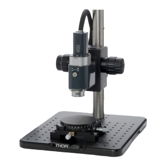
OCTG Series Scanner Chapter 4: Installation 4.3. Integration For the full integration into such a system, please refer to the user manual of the OCT base unit. Figure 4 Fully integrated Callisto System with 900 nm Standard Scanner (Item # OCTG-900) Mounted on a... -
Page 13: Chapter 5 Description
OCTG Series Scanner Chapter 5: Description Description Chapter 5 5.1. Theory 5.1.1. Signal Generation Spectral domain optical coherence tomography (SD-OCT) generates cross-sectional images up to several millimeters deep into tissue. The images are assembled by performing a series of scans at adjacent, increasing depths, allowing 2D and 3D reconstruction of the specimen. -
Page 14: Optical Design
(which reduces the intensity of the light that returns to the fiber), it is significantly more sensitive to the optical phenomena mentioned before. Please contact Thorlabs’ OCT support (see Chapter 11) for details. Figure 6 Diagram of the Dual Path Setup... -
Page 15: Realization
OCTG Series Scanner Chapter 5: Description 5.2.3. Realization The basic optical layout of the OCTG scanner in common path layout is illustrated below in Figure 7. Figure 7 Optical Layout OCTG The output of an FC/APC fiber is collimated and routed to a beam splitter cube. Here the beam is divided into a sample beam and a reference beam, similar to a Michelson interferometer. -
Page 16: Components
In the dual path configuration of the OCTG-NR, the reference path components are not included. Figure 8 Optical Layout OCTG Common Path 5.3. Components The OCTG Standard Scanner are to be used in combination with Thorlabs’ OCT base units. Figure 9 OCT Modules OCTG and OCTG-NR Page 12 MTN004419-D02... -
Page 17: Octg Base Module
For Thorlabs OCT base units, turn off the OCT base unit main power to turn off the light source. Please contact a member of the Thorlabs’ OCT support team to determine if other parts you wish to use are compatible (see Chapter 11). Any modification or servicing of this system by unqualified personnel renders the warranty null and void, leaving Thorlabs free of any liability. - Page 18 OCTG Series Scanner Chapter 5: Description ATTENTION The iris aperture might be damaged by inadequate torque. In positions “open” and “closed” an enlarged mechanical resistance indicates the limit of the travel range. In order to adjust the reference intensity adjustment knob, pull the knob approximately 5 mm outwards until you feel the knob coming to a rest.
-
Page 19: Octg Reference Module
OCTG Series Scanner Chapter 5: Description 5.3.2. OCTG Reference Module The reference module contains a mounted mirror (i.e., retro reflector) that reflects the beam from the light source back into the OCT interferometer. Figure 12 OCTG Reference Module In order to match the optical path length in this reference arm to the optical path length of the light from the sample, it may be necessary to translate the mirror along the axis of the optical system. -
Page 20: Oct Scan Lens Kit (Accessory)
Chapter 5: Description 5.3.3. OCT Scan Lens Kit (Accessory) The OCT scan lens kit from Thorlabs are specially designed accessories to support telecentric scanning over a wide range and to compensate the dispersion mismatch of the scanner. The OCT-LKx are fully compatible with the OCTG. -
Page 21: Reference Arm Adapter (Accessory)
OCTG Series Scanner Chapter 5: Description 5.3.4. Reference Arm Adapter (Accessory) The match the required optical path length and the dispersion for the used OCT scan lens kit the installation of the reference arm adapter OCT-RAx is strongly suggested. If you ordered a reference arm adapter with the OCTG, this item is pre-installed. -
Page 22: Dove Tail Mount
5.3.5. Dove Tail Mount The OCTG ships with a dovetail mount at the back side (as seen in Figure 18 below). This accessory allow the scanner to be mounted in standard Thorlabs OCT-Stand. Figure 18 OCTG-1300 with Dove Tail Mount The OCT-Stand is a dedicated stand for OCTG scanners. -
Page 23: Dimensions
OCTG Series Scanner Chapter 5: Description 5.4. Dimensions The dimensions of the OCTG series standard scanners are given in the following drawing. All dimensions are in mm. Figure 20 Drawing showing Dimensions, Mounting Options, and Focal Plane The opto-mechanical specifications of the OCT scan lens kits are listed in the table below. -
Page 24: Chapter 6 Troubleshooting
Fiber Not Connected Alignment Key is Inserted into Key Slot Poor Reference Aperture is Too Small Open Aperture Clean Fiber Tip (Thorlabs’ MCC-7020 Fiber Light Intensity Fiber Tip is Dirty Connector Cleaner Recommended) Other Reason Contact OCT Service (See Chapter 11) -
Page 25: Chapter 7 Certifications And Compliance
OCTG Series Scanner Chapter 7: Certifications and Compliance Certifications and Compliance Chapter 7 Rev C, April 06, 2016 Page 21... -
Page 26: Chapter 8 Specifications
OCTG Series Scanner Chapter 8: Specifications Specifications Chapter 8 OCTG Optical Specifications Center Wavelength 900 nm, or 1300 nm Clear Aperture Ø6 mm (Max) Reference Length Fine Adjustment -2 mm / +10 mm Scan Distance (Objective Shoulder) 15.0 mm / 28 mm... -
Page 27: Reflectivity Scanning Mirror
OCTG Series Scanner Chapter 8: Specifications 8.1. Reflectivity Scanning Mirror The OCTG series standard scanners are equipped with a semitransparent galvo mirror to enable video camera imaging.* OCTG Mirror 45° S-Pol. Unpolarized P-Pol. 1000 1100 1200 1300 1400 1500 Wavelength (nm) Figure 21 Reflectivity of Scanning Mirroor * In systems delivered prior to February 2017 a coating with different characteristics was used. -
Page 28: Chapter 9 Warranty
(c) items repaired, modified, or altered by any party other than Thorlabs; (d) items used in conjunction with equipment not provided by or acknowledged as compatible by Thorlabs; (e) subjected to unusual physical, thermal, or electrical stress; (f) damaged due to improper installation, misuse, abuse, or storage;... -
Page 29: Chapter 10 Regulatory
10.1. Waste Treatment is Your Own Responsibility If you do not return an “end of life” unit to Thorlabs, you must hand it to a company specialized in waste recovery. Do not dispose of the unit in a litter bin or at a public waste disposal site. -
Page 30: Chapter 11 Thorlabs Oct Support Contact
OCTG Series Scanner Chapter 11: Thorlabs OCT Support Contact Chapter 11 Thorlabs OCT Support Contact If you have a technical question or issue on Thorlabs OCT products, please refer directly to the OCT Support team located in Luebeck, Germany. OCT Support Thorlabs GmbH Maria-Goeppert-Straße 9... - Page 31 OCTG Series Scanner Chapter 12: Thorlabs Worldwide Contacts Chapter 12 Thorlabs Worldwide Contacts USA, Canada, and South America UK and Ireland Thorlabs, Inc. Thorlabs Ltd. 56 Sparta Avenue 1 Saint Thomas Place Ely CB7 4EX Newton, NJ 07860 Great Britain...
- Page 32 M0009-510-885-D...
Need help?
Do you have a question about the OCTG Series and is the answer not in the manual?
Questions and answers