Intel FALCON 8+ User Manual
Unmanned aircraft system
Hide thumbs
Also See for FALCON 8+:
- User manual (191 pages) ,
- Flight manual (147 pages) ,
- Quick start manual (28 pages)
Table of Contents
Advertisement
Quick Links
Advertisement
Chapters
Table of Contents
Troubleshooting

Related Manuals for Intel FALCON 8+


Summary of Contents for Intel FALCON 8+
- Page 1 INTEL ® FALCON™ 8+ UNMANNED AIRCRAFT SYSTEM ENGLISH MAY 2018...
- Page 2 No license of any kind, whether express, implied, statutory, by estoppel or otherwise to any intellectual property rights, technology, software, in each case whether in whole or part, is granted by Intel, or any of its subsidiaries, in this User Manual.
- Page 3 F8 to the F8+ • Created instructions for Intel® High Resolution Imaging Payload • Created instructions for Intel® Imaging Payload with Obstacle Avoidance • Updated battery charging instructions • Added additional system warnings and delete obsolete warnings •...
-
Page 4: Table Of Contents
2.7.2. Packing for shipping ..................85 2.8. SOFTWARE FEATURE PACKAGES ........... 87 2.8.1. Activating Software Feature Packages ............89 2.8.2. Checking Activated Software Feature Packages ........89 2.9. INTEL® FALCON™ 8+ UAV FLIGHT LOGS ........91 © 2018 Intel Corporation. All rights reserved... - Page 5 3.8.1. Launching in GPS-Mode ................128 3.8.2. Launching in Height-Mode ................128 3.8.3. Launching in Manual-Mode .................129 3.9. THE FLIGHT .................... 130 3.9.1. Controlling the Intel® Falcon™ 8+ UAV from the CTR .......131 3.9.2. Mission planning ....................132 3.9.3. In-Flight ........................133 3.9.4. General Operating Tips .................133 3.10.
- Page 6 6. MAINTENANCE, TROUBLESHOOTING, AND SUPPORT ...........193 6.1. MAINTENANCE ..................193 6.1.1. Intel® Falcon™ 8+ UAS firmware updates ..........193 6.1.2. Caring for the Intel® Falcon™ 8+ UAV ............198 6.1.3. Propeller replacement ...................200 6.1.4. Motor rail replacement ..................202 6.1.5. Exchanging a payload adapter ..............207 6.1.6.
-
Page 7: Intel® Falcon™ 8+ Uas
UAV inspections and surveying operations. Small and portable with a maximum take-off weight of only 2.8 kg, but with a payload weight of 0.8 kg, the Intel® Falcon™ 8+ UAV can carry professional cameras like the Sony Alpha 7R, offering the full quality of an airborne image studio. -
Page 8: Safety Guidelines
Therefore, a pilot must have the training and ability to fly the Intel® Falcon™ 8+ UAV in Height-Mode in any situation. Only operate in these environments if you have sufficient training! ©... - Page 9 • GPS-Mode will limit your maximum speed. Flying the Intel® Falcon™ 8+ UAV at wind speeds above 12 m/s is not recommended. Please note that wind conditions on the ground and in the air can differ.
- Page 10 • The pilot of an Intel UAV should always act according to his or her best judgment focusing on the safety of the populace and the environment within which he or she is flying.
-
Page 11: Uas And Safety Check
(any loose part, strange noise from the motors, or any other unusual occurrence), please contact support through your reseller, if you purchased through a reseller, or support at Intel, if you purchased directly from Intel. Please include a detailed description of your observation and photos if applicable. - Page 12 6. Is the User SD card of the Check the User SD card in the back of the “Black Box” (flight logger) Intel® Falcon™ 8+ UAV. If on the Status Dis- □ correctly inserted? play of the CTR there is the message No user...
-
Page 13: Pre-Flight Check
2. Make sure to have an empty and correctly formatted SD card inserted in the camera. □ 3. Are there two batteries fully inserted into the Intel® Falcon™ 8+ UAV, with the colored label facing upwards and secured by the retaining clips? □... -
Page 14: Pre Flight Checklist (Continued)
8. The end of the boot process is marked by a triple beep emitted by the □ Intel® Falcon™ 8+ UAV. During boot up, the Intel® Falcon™ 8+ UAV does not need to stand still. It can be moved - for example, it can be started from a moving boat. - Page 15 19.Switch the motors on (with both hands, only in idle mode). □ While the Intel® Falcon™ 8+ UAV is on the ground with running motors, always keep the left control stick, which controls the height, in the fully downward position.
-
Page 16: Post-Flight Check
1.4. POST-FLIGHT CHECK You must follow these steps closely for a post-flight check: Table 1.4: Post-flight Check List □ 1. Before landing the Intel® Falcon™ 8+ UAV, adjust the camera to a horizontal position. 2. Land the Intel® Falcon™ 8+ UAV. □... - Page 17 9. Store the CTR and all accessories safely in the transport case or in the backpack. CAUTION: ALWAYS REMOVE ALL BATTERIES FROM BOTH THE INTEL® FALCON™ 8+ UAV AND CTR WHEN THE SYSTEM IS NO LONGER IN USE. WARNING VIOLATION OF THESE SAFETY PRECAUTIONS RESULTS IN THE LOSS OF WARRANTY! ©...
-
Page 18: Description Of The System
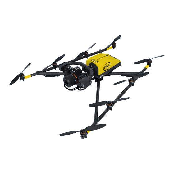
• The Intel® Powerpack Batteries 2.1. THE INTEL® FALCON™ 8+ UAV The following section describes the single parts of the Intel® Falcon™ 8+ UAV. Figure 2.1: The Intel® Falcon™ 8+ UAV Components The Intel® Falcon™ 8+ UAV consists of several components:... - Page 19 USER MANUAL INTEL® FALCON™ 8+ UAS Figure 2.1: The Intel® Falcon™ 8+ UAV Components (continued) The Intel® Falcon™ 8+ UAV bottom view, Carbon Cross with center cross piece, Data antenna arrangement: Video The data link antennas (2.4 GHz) as well as the video link antennas (5.8 GHz) are...
-
Page 20: Central Unit
(7) Retaining clips for the batteries (8) Place for the label with the serial number of the UAV Built inside: • The electronics for flight stabilization and power supply • Diversity Data Link modules • Video Transmitter module © 2018 Intel Corporation. All rights reserved... - Page 21 (1) LED position light (red when UAV is running), same on the right side (green when UAV is running) (2) Vibration dampers (3) Cable tube (which contains, e.g., the cabling of the antennas) © 2018 Intel Corporation. All rights reserved...
-
Page 22: Motor Rails Of The Uav
The motor rails are connected by a carbon cross which consists of four carbon tubes connected by a center cross piece. The antenna cabling is found inside the tubes of the carbon cross. © 2018 Intel Corporation. All rights reserved... -
Page 23: Actively Stabilized Camera Mount (Gimbal)
The communication between the CTR and the Intel® Falcon™ 8+ UAV is ensured by two independent 2.4 GHz digital data links. The preview video is transmitted digitally on 5.8 GHz. The CTR uses the same battery type as the Intel® Falcon™ 8+ UAV. The battery is in © 2018 Intel Corporation. All rights reserved... -
Page 24: Intel® Cockpit Controller (Ctr) Overview
The CTR serves as an interface device to the flight system. It is pre-programmed and ready to use. The Status Display is used for communication between the CTR and the Intel® Falcon™ 8+ UAV. The touchscreen tablet displays the live video preview from the attached camera. -
Page 25: Status Display
USER MANUAL INTEL® FALCON™ 8+ UAS Figure 2.7: Intel® Cockpit Controller (CTR) Overview (continued) The functional elements of the CTR remote control unit are: (1) START/STOP button: starts/stops the motors when the left stick is simultaneously held down (see “STARTING AND STOPPING THE MOTORS”... - Page 26 USER MANUAL INTEL® FALCON™ 8+ UAS Figure 2.7: Intel® Cockpit Controller (CTR) Overview (continued) A headphone port (mini jack) is located on the lower right-hand side of the CTR remote control unit (1). It is possible to connect headphones, which might be helpful under noisy conditions.
-
Page 27: The Status Display
RIGHT button (middle, right side) you can scroll through menus or alter parameters. Enter (right side) is used to enter menus and activate functions. In the following text, it is displayed as ENT. © 2018 Intel Corporation. All rights reserved... -
Page 28: The Touchscreen Tablet
2.2.2. The Touchscreen Tablet The Intel® based Windows® touchscreen tablet has an 8.3-inch screen with a resolution of 1920 X 1200 pixels. It is directly mounted on the remote control unit of the Intel® Cockpit Controller (CTR) and cannot be removed. - Page 29 Yaw (left /right) Yaw (left/right) Horizontal tilt (adjust camera Horizontal tilt (adjust camera horizon) (left/right) horizon) (left/right) Exposure compensation +/- (up/ Switch camera (up/down) down) Shutter speed - Zoom + (when RGB camera is active) © 2018 Intel Corporation. All rights reserved...
-
Page 30: The 2Nd Operator Monitor
Thanks to the 2nd monitor, a camera operator can control the video preview of the camera used. It is connected to the CTR via the HDMI port by a cable. The HDMI port is in the back of the CTR in the upper left corner (see “Intel® Cockpit Controller (CTR) Overview” on page 24). -
Page 31: Payloads - Camera Options
Because of the deep integration of cameras, it is possible to change settings like aperture, shutter speed or zoom (depending on the camera) directly from the remote control unit of the Intel® Cockpit Controller (CTR) and/or the Cockpit Control application on the touchscreen tablet while the system is airborne. To ensure complete integration into the Intel®... - Page 32 USER MANUAL INTEL® FALCON™ 8+ UAS Figure 2.12: Camera Control via the Intel® Cockpit Controller (CTR) All cameras integrated on the Intel® Fal- con™ 8+ UAV can be controlled via the CTR. Several switches on the CTR are assigned to camera controls.
- Page 33 USER MANUAL INTEL® FALCON™ 8+ UAS Figure 2.12: Camera Control via the Intel® Cockpit Controller (CTR) (continued) Setting the Camera Angle The Main Screen of the Status Display shows the camera angle. 0° means the camera is looking straight forward and is leveled horizontally. -90° means the camera is looking down, 90°...
-
Page 34: Changing A Payload (Camera)
2.5.1. Changing a Payload (Camera) Cameras are designed to remain within their gimbal (camera mount). The complete gimbal with camera can be exchanged without tools. The Intel® Falcon™ 8+ UAV automatically identifies the attached camera and the menus of the Status Display on the CTR are changed accordingly. - Page 35 3. Disconnect the ball of the ball link connector of the roll servo out of the adapter slot. 4. Pull out the camera mount gently. Make sure it comes out straight (not at an angle) © 2018 Intel Corporation. All rights reserved...
-
Page 36: Payload And Compass Calibration
The payload calibration can be done indoors with the motors switched off. 1. Attach the payload you are performing the calibration on. 2. Switch the payload ON, then the Intel® Falcon™ 8+ UAV, then the touchscreen tablet and the finally the CTR. - Page 37 PARAMETERS WILL ONLY BECOME ACTIVE AFTER RESTARTING THE SYSTEM. 8. Repeat the above steps for each new payload to be used with the Intel® Falcon™ 8+ UAV. Once a payload has been calibrated, the Intel® Falcon™ 8+ UAV will recall the settings.
- Page 38 INTEL® FALCON™ 8+ UAS To re-adjust the zero position, follow these steps: 1. Switch the Intel® Falcon™ 8+ UAV and the CTR ON as usual. 2. Select the Link Loss Procedure. 3. Push the left control stick of the CTR fully upwards and hold it.
-
Page 39: Sony Alpha 7R Full Frame Camera
Only then should you switch off the Intel® Falcon™ 8+ UAV. If you switch off the Intel® Falcon™ 8+ UAV too early, you will cut the power supply of the camera and risk losing data. - Page 40 Display by pushing ENT > Camera Options > Dial 2 The default functions of Dial 1 and 2 depend on the selected shooting mode on the camera. The table below shows the dependencies. © 2018 Intel Corporation. All rights reserved...
-
Page 41: Sony Alpha 7R Camera Control By Camera Functions
Roll Comp. When Roll Comp. = Off the gimbal will no longer compensate On/Off roll movements of the Intel® Falcon™ 8+ UAV. This can be useful when doing dynamic video flights. 2.5.3.4. Camera Settings The following section describes the most important settings of the camera when used with the Intel®... -
Page 42: Camera Settings By Camera Sony Alpha 7R
The camera menu can be accessed by pushing the MENU button (number (2) above). On the first page of the menu, the Image Size and Quality can be set. Refer to the camera manual for further details. © 2018 Intel Corporation. All rights reserved... -
Page 43: Inspection Payload
TZ71: https://www.panasonicstore.ie/wp-con- tent/uploads/2015/05/DMCTZ70.pdf ZS50: ftp://ftp.panasonic.com/camera/om/ dmc-zs50_adv_om.pdf Please note that the WiFi functionality of these cameras is disabled for the use with the Intel® Falcon™ 8+ UAV. Specifications of the IR camera FLIR Tau 2 640: • Thermal Imager: Uncooled VOx Microbo- lometer •... - Page 44 The micro SD card of the FLIR Tau is inserted at the side of the camera, with the contacts of the micro SD facing towards the camera lens. Each time the Intel® Falcon™ 8+ UAV is switched on, a new, subsequently numbered sub-folder (FLIR0000, FLIR0001, FLIR0002...) is created on the micro SD card.
- Page 45 Always handle the gimbal with care. If you need to tilt the camera manually (when not connected or while the Intel® Falcon™ 8+ UAV is switched off), please do so very cautiously. If too much force is applied, the gear wheels of the servo motors might break.
-
Page 46: Inspection Payload: Ctr Control Layout
ESC, LEFT, RIGHT, ENT (8): Status Dis- play control buttons. (see “Status Dis- play” on page 27). The table below shows the available parameters depend- ing on the shooting mode of the camera. © 2018 Intel Corporation. All rights reserved... -
Page 47: Inspection Payload Control By Status Display
“Adjusting the camera horizon” on page 37. Default = ON. When = Off, the gimbal will no longer Roll Roll Comp. compensate roll movements of the Intel® Falcon™ 8+ UAV. This can be Comp. useful when doing dynamic video flights. On/Off Notes Shooting parameters need to be set directly on the camera before take-off. -
Page 48: Intel® High Resolution Imaging Payload
INTEL® FALCON™ 8+ UAS 2.5.5. Intel® High Resolution Imaging Payload The Intel® High Resolution Imaging Payload consists of a Sony RX1R II camera with a Topcon B111 GNSS receiver. When the Intel High Resolution Imaging Payload is connected, the external Topcon receiver is used as a redundancy backup receiver for the internal GPS receiver and for geo-referencing the images during post-processing. - Page 49 After doing so, switch OFF the Intel Falcon 8+ UAV. If you switch the Intel Falcon 8+ UAV OFF too early, you will cut the power supply to the camera and risk losing data.
- Page 50 2.5.5.2. Camera control by the CTR This section describes how the Sony RX1R II can be operated by using the functional elements of the Intel Cockpit Controller (CTR). Figure 2.21: Sony RX1R II CTR control layout Push Button B1 (1): sets the camera to pre- defined angles +/-90°, +/-45°...
- Page 51 The camera menu can be accessed by pushing the MENU button (number (7) above). On the first page of the menu, the important parameters such as Image Size and Quality can be set. Please refer to the camera manual for further details. © 2018 Intel Corporation. All rights reserved...
- Page 52 Every time an image is triggered, the positional information is written into the log file of the Intel Falcon 8+ UAV. During post-processing this information can be extracted and combined with the images. Please see chapter “INTEL® FALCON™ 8+ UAV FLIGHT LOGS”...
- Page 53 INTEL® FALCON™ 8+ UAS 2.5.5.5. Firmware update For proper operation of the payload, please make sure the Intel Falcon 8+ UAV and the payload is updated to the latest available version. Download the Intel Falcon 8+ UAV firmware from http://intel.com/FalconDownloads and install it as described in “Intel®...
-
Page 54: Intel® Imaging Payload
The Intel® Imaging Payload consists of a Sony R10C RGB camera and an internal compute module board. Additionally the payload is equipped with Intel® RealSense™ technology, which allows the Intel Falcon 8+ UAV to detect and avoid obstacles in its flight path. - Page 55 The microSDHC bus type and speed class, along with the card manufacturer's real- world performance specifications, set the limit for how frequently images can be saved to the media during flights. Using the supplied microSDHC card, Intel has successfully validated repeated contiguous image captures of up to 500 images with a frequency of up to 1 image capture every 1.5 seconds.
- Page 56 Photo images are stored on the payload SD card with the following described conventions. Every time, the Intel Falcon 8+ UAV is switched on, a new image directory with a consecutive number will be created on the payload SD card.
-
Page 57: Confirmation Of Video File Transfer
Video files recorded during the current flight are stored on the camera SD card (not on the payload SD card, see figure “Intel® Imaging Payload Specifications” on page 54). Directly after the flight the pilot has the possibility to transfer the recorded video files from the camera SD card to the payload SD card (see description in the following figure “Confirmation of video file transfer”... - Page 58 000001_201802191200 = directory name with a consecutive mission number (000001) date (YYYY/MM/DD) and time (hh/mm) • MAH00001.MPG = video file with consecutive number (00001) • MAH00002.MPG = video file number (00002) • Etc. © 2018 Intel Corporation. All rights reserved...
- Page 59 If too much force is applied, the gear wheels of the servo motors may break. • Because the camera is powered by the Intel Falcon 8+ UAV battery in order to save weight, the camera switches ON or OFF when the UAV is switched ON or OFF.
-
Page 60: Camera Settings By The Control Menu Items On The Touchscreen Tablet
As soon as a valid GPS signal is available the camera date and time is set directly by the Intel Falcon 8+ UAV using the information embedded in the GPS data. Adjustable camera settings can be accessed on the left or right side of the screen of the touchscreen tablet of the CTR, when activated by tapping on the respective area in the lower left and right corner. - Page 61 The payload also contains updateable firmware. To update the payload firmware of the Intel® Imaging Payload you need to install the Intel Platform Flash Tool (PFT) Lite on a The currently installed firmware version of the payload can be checked by tapping on the “i”...
-
Page 62: Firmware Update Process
Figure 2.28: Firmware update process 1. Install the downloaded Intel Android USB driver on the same PC you installed the PFT. 2. Start the Intel PFT Lite application. 3. Open the firmware (.ZIP) file by selecting in the upper Browse... - Page 63 TURN When doing this a click can be heard. EITHER THE PAYLOAD OR THE 8. While keeping this button pressed UAV UPSIDE DOWN TO PRESS down, power ON the Intel Falcon 8+ AND HOLD THE DNX BUTTON. UAV. LEAVE PAYLOAD This will put the payload into the HORIZONTAL 0°...
- Page 64 Wait for device to enumerate in OS DNX During the flashing process, the Intel PFT will be delayed at around 86% for a short time but continue. After the update is completed, the prog- ress indicator turns green and depicts the message pictured to the left.
- Page 65 INTEL® FALCON™ 8+ UAS 2.5.6.5. Obstacle Avoidance (OA) Obstacle Avoidance (OA) enables the Intel Falcon 8+ UAV to get depth perception of its surroundings. This is enabled by two Intel® RealSense™ Depth Cameras, mounted on the payload, one looking towards the front and another looking 90 degrees to the left.
-
Page 66: Obstacle Avoidance: Directions Covered
The two different cones of the two RealSense modules touch each other in a distance approximately 2600 mm from the camera. CAUTION: THE UAV CANNOT DETECT ANY OBSTACLES OUTSIDE OF THE ABOVE-DESCRIBED FIELDS OF VIEW. © 2018 Intel Corporation. All rights reserved... - Page 67 Turning the OA feature ON and OFF: 1. Start the Intel Falcon 8+ UAV and take-off in GPS-Mode (if possible). 2. Tap on the OA indicator and button in the top left corner of the touchscreen tablet screen.
- Page 68 RealSense modules. For safety purposes, always orient the UAV such that a RealSense module points Note in the direction of flight. © 2018 Intel Corporation. All rights reserved...
- Page 69 Obstacle Avoidance is always disabled in Manual-Mode. Landing the UAV with Obstacle Avoidance During a descent of the UAV, if any obstacle comes into the field of view of the Intel RealSense modules within the pilot-set standoff distance, the UAV may fly backwards or sideways towards the pilot to keep the defined standoff distance.
-
Page 70: System Warnings Related To Obstacle Avoidance
Avoidance is not avail- nection to the RealSense modules has able. been re-established. available! If in flight and in GPS-Mode the Intel Status Display: Falcon 8+ UAV will keep its current OBSTACLE position. To avoid collisions the con- AVOID. N/A! -
Page 71: The Intel® Powerpack Batteries
INTEL® FALCON™ 8+ UAS 2.6. THE INTEL® POWERPACK BATTERIES The Intel® Powerpack batteries power the Intel® Falcon™ 8+ UAV and the Intel® Cockpit Controller (CTR). The battery features a One-Button/Five-LEDs user interface, an intelligent Battery Management System (BMS), automatic balancing, storage mode and charging. -
Page 72: The Intel® Powerpack Battery
USER MANUAL INTEL® FALCON™ 8+ UAS Please note the limitations mentioned on the labels of the Intel® Powerpack Battery. Figure 2.32: The Intel® Powerpack Battery The front of the Intel Powerpack battery The back of the Intel Powerpack battery © 2018 Intel Corporation. All rights reserved... -
Page 73: Charging The Intel® Powerpack Batteries
80% - 100% 2.6.1. Charging the Intel® Powerpack Batteries Upon receipt of new Intel® Powerpack Batteries, you should charge them to 60 - 80% to ensure batteries will not completely drain in storage. To charge the batteries, please use the provided power supply unit. -
Page 74: Operating The Bms Menu
USER MANUAL INTEL® FALCON™ 8+ UAS The Intel® Powerpack Battery has an internal timer which keeps the battery turned ON for 3 seconds after unplugging it from the charger. When a battery with LEDs illuminated is plugged into the Intel Falcon 8+ UAV or the Intel Cockpit Controller (CTR), the respective unit powers ON automatically without the user pressing the ON/ OFF button. -
Page 75: Charging State
51% - 60% ON ON OFF OFF OFF 61% - 70% ON ON ON OFF OFF 71% - 80% ON ON ON ON OFF 81% - 90% ON ON ON ON ON > 90% © 2018 Intel Corporation. All rights reserved... - Page 76 (e. g. too hot during discharge). When a battery shows this behavior, it can still be used to discharge its remaining capacity, but it must not be used anymore. © 2018 Intel Corporation. All rights reserved...
-
Page 77: Battery Update
(no. 1 is the LED most left, no. 5 is the LED most right). Contact the support team at Intel and provide the information which LEDs are lit. In case this state became active during a flight, please also provide a log file of this flight. - Page 78 • Never store or charge a battery inside of your car in extreme temperatures, since extreme temperature could cause a fire. © 2018 Intel Corporation. All rights reserved...
- Page 79 However, storing a fully charged battery has negative effects on its life span. Battery Storage/Charging Maintenance Recommendation • Intel recommends to charge/recharge batteries to a level between 2 and 4 LED’s (40-80%) every 3 months to maintain optimal cell performance and reliability. •...
- Page 80 Alternatively, send the battery for disposal back to Intel. Disposing of this product correctly will help to save valuable resources, and prevent any potential negative effects on human health and the environment, which could otherwise arise from inappropriate waste handling.
-
Page 81: Transport Cases & Intel® Backpack
Intel® Falcon™ 8+ UAS with all its accessories. For easy one-person transportation, the Intel® Falcon™ 8+ UAS cases have retractable handles and wheels. The Intel® Backpack is not safe for air freighting, but very useful for missions in remote areas, since it is light and relatively compact. -
Page 82: Packing Instructions
THE FOAM INLET OF THE PAYLOAD CASE TO AVOID DAMAGES DURING TRANSPORT OR YOU MUST TRANSPORT IT IN THE SPECIAL PAYLOAD CASE (SEE FOLLOWING). Figure 2.37: Packing Instructions for the Intel® Falcon™ 8+ UAS Cases Intel® Falcon™ 8+ System Case This case is used for all necessary parts of your Intel®... - Page 83 USER MANUAL INTEL® FALCON™ 8+ UAS Figure 2.37: Packing Instructions for the Intel® Falcon™ 8+ UAS Cases (continued) Intel® Cockpit Controller (CTR) Case This case contains: CTR with mounted sun shield (1) When transporting the CTR in the case, the sunshield must be arranged like...
- Page 84 The images of the items above are just for illustration purpose and the actual item(s) packed with your Intel® Falcon™ 8+ UAS may differ from the one(s) depicted here depending on, for example, which payload you ordered.
-
Page 85: Packing For Shipping
INTEL® FALCON™ 8+ UAS 2.7.2. Packing for shipping When you got your Intel® Falcon™ 8+ UAS delivered, the system case was encased in a cardboard box. In case you need to send back the UAV system, please pack the system in the respective case like described above. - Page 86 2. Place the two cushions over the ends of the case. 3. Load the case equipped with the cushions into the box. 4. Place the second corrugated insert over the top of the cushioned case and close the box. © 2018 Intel Corporation. All rights reserved...
-
Page 87: Software Feature Packages
Intel Falcon 8+ UAV. The available software feature packages can be purchased at any time and unlocked remotely by your Intel® Falcon™ 8+ UAS reseller. The Intel® Falcon™ 8+ UAS does not need to be sent back. - Page 88 AscTec Navigator Software even before you go out in the field. In the near future AscTec Navigator will be replaced by the advanced flight planning software Intel Mission Control. For up to date information, please check: http://www.intel.com/IntelMissionControl...
-
Page 89: Activating Software Feature Packages
UAS reseller. Once you have purchased your software feature package, you will receive an email with your license key file "f8p_license.asc" which is required to activate the software feature packages. It may come from Intel as an email attachment or from your sales representative. - Page 90 Perpetual Software Feature Packages To check which perpetual software feature packages are activated on your system, turn ON the Intel® Falcon™ 8+ UAV, the touchscreen tablet and the CTR and confirm the Link Loss Procedure. 1. Push ENT to open the menu on the Status Display.
-
Page 91: Intel® Falcon™ 8+ Uav Flight Logs
The Intel® Falcon™ 8+ UAV is constantly logging all flight controller data onto two different storage devices: an SD card inserted in the back of the Intel® Falcon™ 8+ UAV (User SD card) and an internal SD card, which can only be accessed by opening the canopy of the central unit (Internal SD card). -
Page 92: Asctec Navigator Software Flightbook
Intel Mission Control. For up to date information, please check: http://www.intel.com/IntelMissionControl It might happen that the Intel® Falcon™ 8+ UAV cannot access a logging storage device. Usually, it is caused by a mechanical connection issue or a corrupted file system on the storage device. - Page 93 FAT32, allocation unit size: 32 tus Display. Push the kilobytes). After reinserting the SD related arrow LEFT button card into the Intel® Falcon™ 8+ UAV, it on the Intel® Cockpit Con- should again be accessible. troller (CTR) until the Error Message Screen is shown.
- Page 94 No internal SD card to proceed. will be shown. The Intel® Falcon™ 8+ UAV can fly without any active logging device. It is the Note responsibility of the user to make sure that all flights can be properly logged if it is a legal requirement in the country where the system is used.
-
Page 95: Operating The System
INTEL® FALCON™ 8+ UAS 3. OPERATING THE SYSTEM In this chapter, you will find a description how to operate the Intel® Falcon™ 8+ UAS. 3.1. PREPARING THE INTEL® FALCON™ 8+ UAV The following section shows and describes how to prepare the Intel® Falcon™ 8+ UAV for flight. - Page 96 2 seconds until you hear a short beep. After approximately 3 seconds the LEDs on both sides of the Intel® Falcon™ 8+ UAV will be lit and you will hear the internal fan running. The UAV is initialized when the...
-
Page 97: Preparing The Intel® Cockpit Controller (Ctr)
The Intel® Powerpack battery provides power to the CTR as well as the touchscreen tablet (the battery is the same for the Intel® Falcon™ 8+; see “THE INTEL® POWERPACK BATTERIES” on page 71) 3. - Page 98 DISPLAY AND IN THE NOTIFICATION AREA OF THE TOUCHSCREEN TABLET AND THE MOTORS CANNOT BE STARTED. IF THIS OCCURS, SWITCH OFF THE CTR AND SWITCH IT ON AGAIN WITHOUT TOUCHING THE CONTROL STICKS. © 2018 Intel Corporation. All rights reserved...
-
Page 99: The Touchscreen Tablet
3.3. THE TOUCHSCREEN TABLET The Intel® based Windows® touchscreen tablet is directly mounted on the remote control unit of the Intel® Cockpit Controller (CTR) and cannot be removed. It serves as video monitor, displays general flight information and telemetry data, and allows the user to activate automated functions. - Page 100 Now you can: • use the touchscreen as a preview video monitor; • load, modify and save PATH projects and the related waypoints (optional); • load and fly AscTec Navigator Soft- ware projects. © 2018 Intel Corporation. All rights reserved...
- Page 101 Next to the system messages, you find another green bar which indicates the remain- ing battery capacity of the UAV as a percentage (3) followed by the elapsed flight time (4) and the selected flight mode ( ) (5). © 2018 Intel Corporation. All rights reserved...
- Page 102 AscTec Navigator project). Learn more about the AscTec Navigator at http://intel.com/FalconManual. In the near future AscTec Navigator will be replaced by the advanced flight planning software Intel Mission Control. For up to date information, please check: http://www.intel.com/IntelMissionControl...
-
Page 103: Path Projects
With the Cockpit Control application, you can create, load, modify and save PATH projects and any related waypoints. To use this functionality a USB stick (FAT 32 formatted) must be inserted into one of the USB ports, located at the back of the CTR. © 2018 Intel Corporation. All rights reserved... - Page 104 USB stick, which is inserted into the CTR. A waypoint can later be recalled, and the Intel® Falcon™ 8+ UAV will fly to this position and take an image with the stored heading and pitch angle. Camera settings such as shooting mode, or zoom, cannot be stored, and must be set manually before flight.
- Page 105 Tapping on the check mark saves your new project. When creating a new project, it is stored in an automatically generated directory <USB stick>:\CockpitConrol\projects. © 2018 Intel Corporation. All rights reserved...
- Page 106 PATH button in the upper left corner. This opens the window again. PATH PROJECT 8. Tap on the button. Save Project The actual state of your project will be saved on the inserted USB stick. © 2018 Intel Corporation. All rights reserved...
- Page 107 In the lower right corner of the window, the UAV is indicated by an arrowhead with its actual orientation, Height if there is a connection Distance between the UAV and the CTR. © 2018 Intel Corporation. All rights reserved...
- Page 108 Completed waypoints will be marked green in the preview of the touchscreen tablet. CAUTION: WHEN FLYING A PATH PROJECT, THE UAV FLIES A DIRECT STRAIGHT TRAJECTORY BETWEEN THE WAYPOINTS! KEEP THIS IN MIND WHEN TEACH-IN! © 2018 Intel Corporation. All rights reserved...
- Page 109 Tapping on this button sets the selected waypoint as the new start point. Tapping on this button sets the selected waypoint as the new end-point. Tapping on the “delete” button deletes the selected waypoint(s). © 2018 Intel Corporation. All rights reserved...
- Page 110 (top left cor- PATH ner). The window PATH PROJECT opened again (shown to the left). Tap- ping on saves the mod- Save Project ifications to the project. © 2018 Intel Corporation. All rights reserved...
-
Page 111: Asctec Navigator Software Projects
A good GPS signal needs to be available in the complete area in which the UAV will fly in (> 75% = 4 bars). • The space in which the Intel® Falcon™ 8+ UAV will be flying, must be free of obstacles. •... - Page 112 Tapping on the check mark in the lower right corner under the Map Preview, transfers the exported project onto the touchscreen tablet. The window with additional flight information, in the lower right corner changes to video pre- view © 2018 Intel Corporation. All rights reserved...
- Page 113 APPROACH WAYPOINTS OF THE MATRIX IN A STRAIGHT LINE, ASCENDING (OR DESCENDING) CONTINUOUSLY BY ITSELF IF NECESSARY! 3. Intel® Falcon™ 8+ UAV starts to fly the mission. 4. Completed waypoints will be marked green on the preview of the touchscreen tablet.
- Page 114 USER MANUAL INTEL® FALCON™ 8+ UAS A green waypoint indicates that the Intel® Falcon™ 8+ UAV successfully passed the waypoint, sent a trigger command to the camera, and a tag Note was created in the log. It does not necessarily mean that the camera successfully triggered, and stored the image.
-
Page 115: Automated Start-Up Checks
3.4.1. Regional Setting If the Intel® Falcon™ 8+ UAV is switched on in a different region than last time, it will automatically check and if necessary configure all radio parameters to comply with the new region. This is necessary because different regions (e.g. FCC or CE compliant) may have different limits regarding the transmission power. -
Page 116: Magnetic Field Warning
Status Display. 3.4.2. Magnetic Field Warning In flight, the Intel® Falcon™ 8+ UAV uses algorithms to detect possible disturbances of the compass sensors. If there are discrepancies between the magnetometer output and the expected orientation, the UAV's heading is estimated using the other available IMU (Inertial Measurement Unit) sensors. -
Page 117: The Link Loss Procedures
1.5 m/s until it lands. WARNING IF THE BATTERY IS LOW AT THE END OF A FLIGHT, THE EXTRA POWER NEEDED FOR THE ASCENT COULD DEPLETE THE BATTERY AND LEAD TO A CRITICAL SITUATION. © 2018 Intel Corporation. All rights reserved... -
Page 118: New Home Position
Status Display) and the Link Loss Procedure is activated, the UAV will automatically switch to GPS-Mode (a is shown in the upper right corner of the Status display) if a GPS signal is available. © 2018 Intel Corporation. All rights reserved... - Page 119 (while not connected) and latitude and longi- tude of last known position will be displayed. Situations with varying GPS reception • If no GPS reception is available, when a data link connection is lost, the Intel® Falcon™ 8+ UAV will use Direct Landing. •...
-
Page 120: Flight Modes
USER MANUAL INTEL® FALCON™ 8+ UAS 3.6. FLIGHT MODES The Intel® Falcon™ 8+ UAV can be operated in three different flight modes: • GPS-Mode • Height-Mode • Manual-Mode Flying in GPS-Mode is easiest as it provides the highest level of automation. -
Page 121: Gps-Mode
Maintain its position within the limits of the GPS accuracy (approximately 2 – 5 m). • Keep its height within the limits of the height controller (approximately 1 – 3 m). • Compensate for wind speeds up to 12 m/s. © 2018 Intel Corporation. All rights reserved... -
Page 122: Gps Accuracy
CONTROL THE POSITION MANUALLY ON THE CTR. Figure 3.14: GPS accuracy The GPS module of the Intel® Falcon™ 8+ UAV supports GPS and GLONASS. Under ideal conditions, the horizontal accuracy can reach around +/- 2 m. The short-term accuracy is usually higher, because of the data fusion with other available sensor outputs from the IMU. - Page 123 The canopy of the Intel® Falcon™ 8+ UAV is made from a material which does not influence the satellite signals, but anything on the top of the Intel® Falcon™ 8+ UAV can potentially disturb the signal. Never cover the GPS receiver module nor the antenna area to ensure best possible GPS reception.
- Page 124 GPS-Mode. Compass Error Estimation In addition to the compass sensors of the Intel® Falcon™ 8+ UAS, the UAV is equipped with a compass error estimation algorithm. The compass error estimation uses, among others, GPS-data to estimate the heading of the UAV.
-
Page 125: Height-Mode
(using the right control stick, which controls pitch and roll) means the UAV will roll 50° to the left. With this configuration, the wind direction and speed will influence the direction and speed of the UAV. © 2018 Intel Corporation. All rights reserved... -
Page 126: Manual-Mode
Manual-Mode! In most cases with full payload, the system will start to descend. Be prepared to give some thrust to counteract the described effect when switching to Manual-Mode. © 2018 Intel Corporation. All rights reserved... -
Page 127: Starting And Stopping The Motors
Always keep a safe distance from people when starting! • While the Intel® Falcon™ 8+ UAV is on the ground with running motors, always keep the left control stick, which controls the height, in the fully downward position to avoid any unintentional take-off. -
Page 128: Launching In Gps-Mode
4. Keep the right control stick centered (no pitch and roll) and push the left control stick completely up (= ascend) to launch the drone. 5. Keep ascending until a safe height is reached. Be aware that the Intel® Falcon™ 8+ UAV may drift a little and correction might be required. -
Page 129: Launching In Manual-Mode
In Manual-Mode the pilot must control all axes. There is no automation regulating, nor preventing pilot errors. Normally this mode should not be used. To launch the Intel® Falcon™ 8+ UAV in Manual-Mode: 1. Push the GPS and HGT buttons on the CTR simultaneously. -
Page 130: The Flight
• Thrust: ascend or descend along the yaw axis. All propellers turn faster or slower to ascend or to descend. © 2018 Intel Corporation. All rights reserved... -
Page 131: Controlling The Intel® Falcon™ 8+ Uav From The Ctr
BY DESCENDING AND SIMULTANEOUSLY FLYING SIDEWAYS OR BACKWARDS. 3.9.1. Controlling the Intel® Falcon™ 8+ UAV from the CTR The standard control mode is called Mode 2. In this mode, the left control stick controls thrust and yaw. The right control stick controls pitch and roll. -
Page 132: Mission Planning
Be aware of the size of the area in which you plan to fly. Always ensure the Intel® Falcon™ 8+ UAV has enough battery capacity to fly back to the home position – even if the wind unexpectedly increases. -
Page 133: In-Flight
Try to avoid situations such as: • Strong wind or turbulences • Interference or lost data links • Weak or shadowed GPS signal (“Shadowing” on page 123) © 2018 Intel Corporation. All rights reserved... -
Page 134: In-Flight Emergencies
Analyze each mission regarding (but not limited to) the above-mentioned factors. If you find that the Intel® Falcon™ 8+ UAV does not react to control inputs as expected, for example, inaccurate position control due to bad GPS reception), immediately activate Height-Mode. - Page 135 CTR. Because of the triple redundant flight control of the Intel® Falcon™ 8+ UAV there is a very low probability for this malfunction to occur. © 2018 Intel Corporation. All rights reserved...
- Page 136 Try to shorten the distance to the UAV by walking towards it. Simultaneous loss of GPS The Intel® Falcon™ 8+ UAV will activate the Link Loss reception, and data link con- Procedure because of the lost data link connection. nection, between UAV and...
- Page 137 If still not enough thrust is available, it will start drifting but still try to hold the attitude. Only if physically impossible, the attitude of the system will also be compromised. © 2018 Intel Corporation. All rights reserved...
- Page 138 Table 3.5: Operational guidelines in case of emergency (continued) EVENT POSSIBLE ACTION In GPS-Mode the Intel® Falcon™ 8+ UAV can fly in wind speeds up to 12 m/s. If GPS-Mode is active and there are gusts exceeding 12 m/s you must: 1.
- Page 139 Before you take off you can assure the UAV will stay in the allocated space. You can limit the maximum distance and height of the airspace the Intel Falcon 8+ UAV is flying in by setting specific values which will not be exceeded by the UAV. The center of this bounding box is set to the position of the UAV where is activated.
- Page 140 Try to activate the function from RETURN TO HOME the CTR to bring the Intel Falcon 8+ UAV back to where it took off by pushing the dedicated button on the CTR (see “Intel® Cockpit Controller (CTR) Over- view” on page 24).
-
Page 141: Landing
5. Right before touch-down – at 0.2 - 0.3 m – move the left control stick down gradually until the UAV lands on the ground. While the Intel® Falcon™ 8+ UAV is on the ground with running motors, always keep the left control stick in the fully downward position to avoid any unintentional take-off. -
Page 142: Landing In Manual-Mode
5. Right before touch-down – at a height of 0.2 - 0.3 m – move the left control stick down gradually until the UAV lands on the ground. While the Intel® Falcon™ 8+ UAV is on the ground with running motors, always keep the left control stick in the fully downward position to avoid any unintentional take-off. -
Page 143: Switching Off The Uas
Let go of the button. 3.12. WARNINGS The Intel® Falcon™ 8+ UAS displays all warnings which might occur, in the bottom line of the Status Display and in the notification area at the top of the touchscreen tablet. When there is no warning to display, the bottom line of the Status Display shows On the tablet is shown in the notification area. -
Page 144: Possible Warnings
Status Display flashes. Status Display: The temperatures of the BATTERY OVERHEAT! UAV batteries are out- Vibration on the CTR Tablet: Falcon battery side the allowable range temperature high! © 2018 Intel Corporation. All rights reserved... - Page 145 If so, error. Land now! because something is the joystick electronics may actually broken. be broken. In this case please get in touch with Intel support. © 2018 Intel Corporation. All rights reserved...
- Page 146 Error Message Screen page 166 CHECK STATUS of the Status Display. DISPLAY! The following messages are only shown if an Intel® Imaging Payload is mounted (see “Intel® Imaging Payload” on page 54). Status Display: OBSTACLE The Intel RealSense modules cannot be AVOID.
- Page 147 Shown only on tablet getting too hot, might high! shut down soon). No SD card in the pay- load (card not inserted Payload SD card Shown only on tablet or not properly missing! inserted). © 2018 Intel Corporation. All rights reserved...
- Page 148 Table 3.6: Possible Warnings (continued) SHOWN TEXT REASON SIGNALS / NOTES The following message is only shown if an Intel® High Resolution Imaging Payload is mounted (see “Intel® High Resolution Imaging Payload” on page 48). Possible workaround: • Wait several minutes. It...
-
Page 149: Critical Battery Levels & Warnings Of The Uas
THE UAV MUST BE LANDED IMMEDIATELY AFTER THESE WARNINGS. Battery warnings of the UAV The Intel Falcon 8+ takes many data points into account to calculate the remaining flight time. These include, among others, the current average power consumption, remaining charge of the battery and the potential of one battery being depleted sooner than the other. - Page 150 Pos- Text on the tablet: No battery redundancy! sible reasons could be but are not limited to: • One battery was not cor- rectly inserted • One battery has a defec- tive cell. © 2018 Intel Corporation. All rights reserved...
-
Page 151: Magnetic Field Warning
While starting the Intel® Falcon™ 8+ UAV, a magnetic field warning may occur. Usually disturbances on the ground come from underground lines and can quickly be resolved by switching off the Intel® Falcon™ 8+ UAV, moving it to a different spot and starting from the new location. - Page 152 UAV in the attempt to hold the exact position. To resolve this warning: 1. Switch OFF the Intel® Falcon™ 8+ UAV, the touchscreen tablet and the CTR. 2. Move the UAV to a different spot and switch the complete system ON again.
- Page 153 USER MANUAL INTEL® FALCON™ 8+ UAS In flight, the Intel® Falcon™ 8+ UAV uses algorithms to detect possible disturbances of the compass sensors. If there are discrepancies between the magnetometer output and the expected orientation, the UAV's heading is estimated using the other available IMU sensors.
-
Page 154: Data Link Warnings
SIGNALS EXPLANATION Acoustic: “Link weak!” Tactile: Vibration on CTR The Intel® Falcon™ 8+ UAV has two fully independent Visual on the Status Display: data link connections. In case one link is disturbed, the message is shown. Nevertheless, the LINK WEAK system can still be fully controlled via the second independent link, on a different channel in the 2.4... -
Page 155: Gps Warning
In case of this message push once the arrow LEFT but- Motor failure. Land ton of the Status Display, when the Main Screen is now! shown. This opens a screen which helps identifying the motor causing the warning. © 2018 Intel Corporation. All rights reserved... -
Page 156: Asctec Trinity Control Unit System Warnings
FIXES UUID chip not Serial Number functional (can- is 31000 UUID chip License Contact sup- not be installed / (default), no mal- chip port. not programmed flags can be function! / defective). stored. © 2018 Intel Corporation. All rights reserved... - Page 157 PACKAGE not feature be used. acquire miss- unlocked. installed ing features. Position Sensor input data Restart sys- data cor- Unusual behav- corrupt! tem or con- rupt - criti- Position tact support. cal! fusion disabled! © 2018 Intel Corporation. All rights reserved...
- Page 158 Insert / refor- of central unit No external SD mat SD card; No user SD SD Card faulty (missing, data logging use a different card! full, file system (NAV2 data). SD card. corrupt). © 2018 Intel Corporation. All rights reserved...
- Page 159 Navigation command sent to send the new progress -> the UAV will be flight parame- ignored and the ters again. ignored! current survey flight will be con- tinued. © 2018 Intel Corporation. All rights reserved...
- Page 160 EEPROM. faulty Run payload calibration Payload again. If the Payload calibra- Possibly bad calibration Calibration message is tion failed. yaw alignment. displayed successful! again, contact the support. © 2018 Intel Corporation. All rights reserved...
- Page 161 No tempera- Calibration Contact sup- ture - critical! port. calibra- tion found! Acc and/or Calibration Contact sup- calibra- - critical! port. tion missing! © 2018 Intel Corporation. All rights reserved...
- Page 162 No video recep- Video with the video contact the corrupted tion. flash. support and (A, F, I, M provide the or S) exact error message including the letter in brackets. © 2018 Intel Corporation. All rights reserved...
- Page 163 1 motor Motor bus connection Not all controllers have controller has communi- problem, do Motors not given a status failed. cation not fly! Con- detected update. tact support. UAV will not start/ take off. © 2018 Intel Corporation. All rights reserved...
- Page 164 Land turbed. where the now! issue occurred. Communication Communica- Motor bus Motor bus loss from all tion or com- Check con- communi- motor control- plete hardware nections. working! cation lers. failure. Land now! © 2018 Intel Corporation. All rights reserved...
-
Page 165: Operational Limitations
Above these limits the UAV will not be able to hold its position. • Intel® Falcon™ 8+ UAV operating temperature: -5 °C and 45 °C (23 °F to 113 °F). • Intel® Cockpit Controller operating temperature: -5 °C and 45 °C (23 °F to 113 °F). -
Page 166: Status Display
In this chapter, you will find a description of all possible messages and operations using the Status Display. 4.1. STATUS DISPLAY OVERVIEW The Status Display of the Intel® Cockpit Controller (CTR) shows all relevant information for flying. Figure 4.1: Status Display... -
Page 167: Status Display Menu Structure
CTR, you between the last known you back to should push CTR and the position of the the Main ENT. The fol- UAV” on UAV are Screen. lowing screen page 212. shown: appears: © 2018 Intel Corporation. All rights reserved... - Page 168 “LINK LOSS PROCEDURE” on page 116. Pushing the RIGHT/LEFT arrow buttons in the Main Screen leads you to different screens. For more information about these screens see “The Main Information Screens” on page 178. © 2018 Intel Corporation. All rights reserved...
-
Page 169: Battery Status
• analyzer accuracy mode • UAV Orien- • Signal • Velocity tation quality accuracy • Possible • Possible • Possible warnings warnings Warnings • Flight • Flight • Flight mode mode mode © 2018 Intel Corporation. All rights reserved... -
Page 170: Asctec Trinity Control Unit System Warnings
Number of mode each bat- batteries tery in per- inserted cent • Number of • Number of errors errors Pushing the RIGHT/LEFT arrow buttons in these screens brings you back to the Main Screen. © 2018 Intel Corporation. All rights reserved... - Page 171 ComeHome different place. position High regardless if selected as the UAV is in Link Loss Pro- the air or on cedure. the ground, and brings you back to the Main Screen. © 2018 Intel Corporation. All rights reserved...
-
Page 172: Circle Of Interest
In this screen, decide if you you can start want a cylin- the function, drical or a and decide spherical pan- how many pic- orama. tures are taken during one rotation of the UAV. © 2018 Intel Corporation. All rights reserved... - Page 173 Display is When select- found in the Camera respective sec- , the Options tion in “PAY- next screen LOADS - depends on CAMERA the mounted OPTIONS” on payload (cam- page 31. era). © 2018 Intel Corporation. All rights reserved...
-
Page 174: Quick Surveying Assistant
• Enter the menu page 36 • Link FalconID point you want loss • Format to control. proc. User SD • Falcon • Bounding Info • Video Bind © 2018 Intel Corporation. All rights reserved... - Page 175 ESC to factory is only for ser- brings you defaults if the vice personal. back to the connection to menu. the UAV ID was lost. A new pairing has to be done. © 2018 Intel Corporation. All rights reserved...
- Page 176 91 for allows to for- cess starts and Main Screen. further details. mat the User a progress bar and pushing SD card. is shown. ENT opens the following screen. © 2018 Intel Corporation. All rights reserved...
- Page 177 UAV where brings you Bounding back to the is acti- Main Screen. vated. When the UAV reaches the set radius or alti- tude it stops and will not fly any further. © 2018 Intel Corporation. All rights reserved...
-
Page 178: The Main Information Screens
Displays the UAV orientation regarding its starting position. The displayed V-shape of the UAV will turn respectively when the heading of the Intel® Falcon™ 8+ UAV is changed. This can be of help when the orientation of the UAV is difficult to see in low contrast situations such as when flying in front of dark trees. - Page 179 = Number of satellites which can be Sats: received. = Horizontal accuracy in meters (m). Hor.Acc. = Velocity accuracy in meters per sec- Vel.Acc. ond (m/s). = Status line. This is the same information as on the Main Screen. © 2018 Intel Corporation. All rights reserved...
- Page 180 = Flight Mode. This is the same information as on the Main Screen. = Roll angle of the UAV. Roll = Heading direction of the UAV = Status line. This is the same information as on the Main Screen. © 2018 Intel Corporation. All rights reserved...
- Page 181 (= can’t fly home) warn- N2C:n´t fly home - ing from 2nd Trinity flight controller (no GPS sig- nal and activated). Goto Home in status line. Shown whenever <- Check Msg there is a system warning. © 2018 Intel Corporation. All rights reserved...
- Page 182 Charge state of the UAV in percent = Number of batteries inserted in # of Bat.: the UAV = Number of errors Error: = Status line. This is the same information as on the Main Screen. © 2018 Intel Corporation. All rights reserved...
-
Page 183: Special Functions
5. SPECIAL FUNCTIONS This chapter offers a description of several functions to perform semi-automatic flights directly from the Intel® Cockpit Controller (CTR). Most of these functions can only be executed in GPS-Mode and require a good GPS reception. 5.1. CIRCLE OF INTEREST (COI) This function is an optional part of the Inspection Package (see Chapter 2.8 Software... -
Page 184: Panorama
The speed of the Intel® Falcon™ 8+ UAV is set automatically to always have 2 seconds in between images. Any photo editing software with panorama stitching functionality, or specialized panorama software, may be used to do the image post processing. - Page 185 There are two options available, cylindrical and spherical panorama. Figure 5.2: Cylindrical Panorama To create images for a cylindrical panorama, the Intel® Falcon™ 8+ UAV will keep its current position and do one 360° turn around the yaw axis, with one fixed tilt angle of the camera.
- Page 186 ENT opens the next Cylindric screen. By default, the Intel® Falcon™ 8+ UAV will take an image every 30° while turning around the yaw axis. Meaning that 360°/30° = 12 images will be created. To adjust the rota- tion angle, use the arrow LEFT button to activate and confirm by pushing ENT.
- Page 187 INTEL® FALCON™ 8+ UAS Figure 5.3: Spherical Panorama To create images for a spherical panorama, the Intel® Falcon™ 8+ UAV will keep its current position, and do multiple 360° turns around the yaw axis. The camera tilt angle is set to point downwards during the first turn. With every subsequent turn, the camera will be tilted upwards a bit further, until it will point fully upwards during the last turn.
-
Page 188: Quick Surveying Assistant
CTR without any prior planning on a computer. To do so, the Intel® Falcon™ 8+ UAV is placed in one corner of the area to be mapped, and the key parameters are entered: attached camera / lens combination, desired ground sample distance, image overlaps, length of the lines and number of lines. - Page 189 More complex flights should be planned and performed with the AscTec Navigator Software. In the near future AscTec Navigator Software will be replaced by the advanced flight planning software Intel Mission Control. For up to date information, please check: http://www.intel.com/IntelMissionControl. Figure 5.4: Quick Surveying Assistant Pushing ENT in the Main Screen opens the screen to the left.
- Page 190 INTEL® FALCON™ 8+ UAS Figure 5.4: Quick Surveying Assistant (Continued) Select camera/lens combination attached Select Cam: to the Intel® Falcon™ 8+ UAV. The most commonly used cameras are available as a preset. shows the angle of the Field Of View. FOV: shows the resolution of the single picture in pixels.
- Page 191 :During the flight a bar shows the progress. Flying... At the end of the matrix the Intel® Falcon™ 8+ will stop automatically. Push ESC to exit the screen and go back to the main menu.
-
Page 192: Waypoint Navigation Using Asctec Navigator Software
(see “AscTec Navigator Software Projects” on page 111). At each waypoint an image is triggered, and the current GPS position is stored in the Intel® Falcon™ 8+ UAV log. Images and GPS information can later be used in photogrammetry software to create orthomosaics, digital surface models or 3D models. -
Page 193: Maintenance, Troubleshooting, And Support
This chapter provides you with answers for questions which might appear during your work with the Intel® Falcon™ 8+ UAS. In the first section, we inform you how to keep your Intel® Falcon™ 8+ UAS up to date and give instructions to preserve the functionality. - Page 194 Outbound license file (OBL). Please read the license file before installing the firmware/software. By installing the firmware/software, you agree to the included OBL. The firmware of the Intel® Falcon™ 8+ UAV consists of two different components: • NAV: Navigational Processor = flight controller module of the AscTec Trinity Control Unit.
-
Page 195: Updating The Intel® Falcon™ 8+ Uav
Controller, try reformatting the USB stick with the aforementioned parameters. 6.1.1.1. Updating the Intel® Falcon™ 8+ UAV The Intel® Falcon™ 8+ UAV is updated by a file called TRINITY.ATF. This file must be copied onto the USB stick before you start. -
Page 196: Firmware Update For The Ctr
Status Display. Falcon Info To save time, it is possible to do the firmware update of the CTR and the Intel® Note Falcon™ 8+ UAV in parallel. © 2018 Intel Corporation. All rights reserved... -
Page 197: Firmware Update For The Cockpit Control Application
The firmware update of the Cockpit Control application can only be done with Note the USB ports 2 to 4 on the backside of the CTR (“Intel® Cockpit Controller (CTR) Overview” on page 24). Table 6.3: Firmware Update for the Cockpit Control Application... -
Page 198: Caring For The Intel® Falcon™ 8+ Uav
“UAS AND SAFETY CHECK” on page 11). • We recommend an annual check from the manufacturer, during which the system is fully tested. For details please contact your reseller or Intel support. Cleaning If necessary, you should clean the UAV after the mission, and before storing. - Page 199 Best practice is to always keep the UAV in the closed approved case. Transportation Only transport the system in the case or the backpack as described, see “TRANSPORT CASES & INTEL® BACKPACK” on page 81. © 2018 Intel Corporation. All rights reserved...
-
Page 200: Propeller Replacement
MAY BECOME UNABLE TO COMPENSATE, WHICH MAY CAUSE A CRASH; AND • IF THIS HAPPENS WITH MORE THAN ONE MOTOR, IT IS VERY LIKELY THAT THE UAV WILL BECOME UNSTABLE, UNCONTROLLABLE, AND CRASH. © 2018 Intel Corporation. All rights reserved... - Page 201 (any loose part, strange noise from the motors, or any other unusual occurrence), prepare the UAS to do a test flight on a wide open field without any close by obstacles. © 2018 Intel Corporation. All rights reserved...
-
Page 202: Motor Rail Replacement
Follow the Pre-flight Check (“PRE-FLIGHT CHECK” on page 13) thoroughly to prepare the Intel Falcon 8+ UAS for take-off. Once airborne, perform flight maneuvers in all directions and observe if the UAV performs as expected. If it does, land the system and follow the Post-flight Check (“POST-FLIGHT CHECK”... - Page 203 USER MANUAL INTEL® FALCON™ 8+ UAS Figure 6.3: Removing a motor rail from an Intel Falcon F8+ UAV 1. Remove the screw M2x18 mm TX, FK of the motor rail at the front end of the UAV. Use a T6 torx screw driver.
- Page 204 INTEL® FALCON™ 8+ UAS Figure 6.3: (continued) Removing a motor rail from an Intel Falcon F8+ UAV 6. Push the motor rail straight out of the connecting plug of the rear cross tube. Before mounting a motor rail, perform the following checks: Figure 6.4:...
- Page 205 CAUSE LACK OF CONTROL AND CRASHING, AS WELL AS POSSIBLE INJURY TO PERSONS OR PROPERTY. Figure 6.5: Mounting a motor rail onto an Intel Falcon F8+ UAV 1. Align the motor rail to the cross tubes. Make sure there is no horizontal tilt of the motor rail.
- Page 206 USER MANUAL INTEL® FALCON™ 8+ UAS Figure 6.5: (continued) Mounting a motor rail onto an Intel Falcon F8+ UAV 4. Rotate the motor rail by a small amount until it fits. NOTICE: Possible breakage of the connector. Do not rotate the motor rail too much.
-
Page 207: Exchanging A Payload Adapter
Follow the Pre-flight Check (“PRE-FLIGHT CHECK” on page 13) thoroughly to prepare the Intel Falcon 8+ UAS for take-off. Once airborne, perform flight maneuvers in all directions and observe if the UAV performs as expected. If it does, land the system and follow the Post-flight Check (“POST-FLIGHT CHECK”... - Page 208 Use a T6 torx screw driver. Make sure not to apply force to the servo motor. 2. Disconnect the front plate and the back plate of the payload adapter. 3. Disconnect the 10 pin wire connector. © 2018 Intel Corporation. All rights reserved...
- Page 209 Figure 6.8: Attaching a new payload adapter 1. Attach the board to the back plate. 2. Attach the ball bearing to the front plate. 3. Slide the front plate assembly onto the rod of the payload. © 2018 Intel Corporation. All rights reserved...
-
Page 210: Updating A Payload From An Asctec Falcon 8 Uav To An Intel Falcon 8+ Uav
No calib on payload found 3. Update the eeprom flash of the payload. Contact the Intel support team and provide the following information: • Payload type (Sony Alpha 7R or Inspection Payload TZ71) © 2018 Intel Corporation. All rights reserved... - Page 211 The payload calibration will resolve this error message. If the payload shall again be used on the Intel Falcon 8+ UAV, it is sufficient to mount the payload adapter again and perform a payload calibration. The update file "f8p_license.asc"...
-
Page 212: Troubleshooting
The UAV and the CTR are pre-configured ex works. Nevertheless, when the Intel® Falcon™ 8+ UAV and the CTR are powered up for the first time, the Status Display will show the Start Screen and it is necessary to set up the connection between UAV and CTR. -
Page 213: Analyzing Data Link Connection Issues
Take a new CTR and connect it with the problematic Intel® Falcon™ 8+ UAV and repeat the test. If the issue persists it is very likely the Intel® Falcon™ 8+ UAV, if the issue disappears it very likely is coming from the CTR. -
Page 214: No Preview Video On The Touchscreen Tablet Of The Ctr
When the issue has been isolated, please contact the support team, describe your finding precisely and be prepared to provide log files of the flight tests. If you do not have a second CTR / Intel® Falcon™ 8+ UAV available, contact Intel support. -
Page 215: Possible Warning
FAT32, allocation unit size: 32 Display. Push the related arrow accessed. kilobytes). After reinserting the SD LEFT button on the CTR until card into the Intel® Falcon™ 8+ UAV, it the Error Message Screen is should be accessible. shown. No user SD card will be shown. -
Page 216: Support
The Intel® Falcon™ 8+ UAV can fly without any active logging device. It is the Note responsibility of the user to make sure that all flights can be properly logged if it is a legal requirement in the country where the system is used. - Page 217 • Log files from the User SD card, see “INTEL® FALCON™ 8+ UAV FLIGHT LOGS” on page 91. Please indicate as precisely as possible the log file number in which the incident occurred, or note the exact local time at which the incident occurred.
-
Page 218: Technical Specification
USER MANUAL INTEL® FALCON™ 8+ UAS 7. TECHNICAL SPECIFICATION Figure 7.1: Technical Data © 2018 Intel Corporation. All rights reserved... - Page 219 MAX. RANGE VIDEO LINK** 500 m (FCC and CE version) (1640 feet) MAX. TOLERABLE WIND SPEED 12 m/s (26 mph) (GPS-Mode) 16 m/s (35 mph) (Height-Mode, Manual- Mode) © 2018 Intel Corporation. All rights reserved...
- Page 220 6 to 10 m/s (13 to 22 mph) HEIGHT-MODE 3 m/s (6 mph) GPS-MODE 3 m/s (6 mph) MAX. TURN RATE MANUAL-MODE / HEIGHT-MODE 115°/s GPS-MODE 75°/s MAX. PITCH AND ROLL ANGLES MANUAL-MODE / HEIGHT-MODE 50° GPS-MODE 45° © 2018 Intel Corporation. All rights reserved...
- Page 221 4 x USB, 1 x HDMI INTEL® POWERPACK BATTERY TYPE Lithium Polymer (LiPo) 4S CAPACITY 4000 mAh VOLTAGE (NOMINAL) 14.8 V ENERGY 59.2 Wh OPERATING TEMPERATURE*** -5 °C to 40 °C (23 °F to 104 °F) © 2018 Intel Corporation. All rights reserved...
- Page 222 ** The pilot is responsible for knowing and complying with all laws and regulations applicable to the airspace in which the Intel® Falcon™ 8+ System is operated. Juris- dictions have different safety rules related to authorization for flying unmanned air- craft;...
- Page 223 USER MANUAL INTEL® FALCON™ 8+ UAS Table 7.1: Technical Data (Continued) *** The maximum temperature for the Intel® Powerpack depends on the system and the configuration it is used with: • The Intel® Falcon™ 8+ combined with the Intel® Cockpit Controller - operating temperature is 45°C (113°F)
-
Page 224: List Of Figures
2.9 The Touchscreen Tablet .....................28 2.10 Independent Camera Control (ICC) ................28 2.11 2nd Operator Monitor Package ..................30 2.12 Camera Control via the Intel® Cockpit Controller (CTR) ........32 2.13 Installing the Camera Mount ..................34 2.14 Removing the Camera Mount ..................35 2.15 Sony Alpha 7R and SD Card Slot .................39 2.16 Sony Alpha 7R CTR Control Layout ................40... - Page 225 INTEL® FALCON™ 8+ UAS 2.36 Transport Cases & Backpack ..................81 2.37 Packing Instructions for the Intel® Falcon™ 8+ UAS Cases ........82 2.38 Packing Instructions for the cardboard box for the UAV system case ..85 2.39 Show Activated Perpetual License ................90 2.40 Show activated annual license ..................90...
- Page 226 USER MANUAL INTEL® FALCON™ 8+ UAS 6.3 Removing a motor rail from an Intel Falcon F8+ UAV ........203 6.4 Checks do be done before mounting a motor rail ..........204 6.5 Mounting a motor rail onto an Intel Falcon F8+ UAV .........205 6.6 The parts of the payload adapter ................208...
-
Page 227: List Of Tables
5.1 Image Positions of Spherical Panorama Set To 19 mm Focal Length ..188 5.2 Image Positions Of Spherical Panorama Set To 30 mm Focal Length ..188 6.1 Updating the Intel® Falcon™ 8+ UAV ................195 6.2 Firmware Update for the CTR ..................196 6.3 Firmware Update for the Cockpit Control Application ........197... -
Page 228: Index
Camera Options, Status Display ..................41 Central Unit ..........................20 Changing a Payload (Camera) ....................34 Charging ............................73 Charging Cycles ..........................75 Charging State ..........................74 Circle of Interest (COI) ......................183 Cleaning ............................198 Climb/Sink Rates ........................220 Compass calibration ......................36, 37 © 2018 Intel Corporation. All rights reserved... - Page 229 USER MANUAL INTEL® FALCON™ 8+ UAS Compass Error Estimation ....................124 Controlling the Intel® Falcon™ 8+ UAV, CTR ...............131 Distance Guard ..........................69 Distance Hold ..........................68 DNX button ...........................63 Emergencies, In-flight ......................134 Establishing a connection between the CTR and the UAV ........212 Firmware update Sony R10C ....................61...
- Page 230 Inspection Payload, General Care ..................45 Intel Platform Flash Tool (PFT) ....................61 Intel® Backpack ...........................81 Intel® Cockpit Controller (CTR) ................. 23, 221 Intel® Falcon™ 8+ UAS ........................ 7 Intel® Falcon™ 8+ UAV ....................18, 219 Intel® Falcon™ 8+ UAV, Caring for ..................198 Intel®...
- Page 231 Payload adapter ........................207 Payload calibration ........................36 Payloads - Camera Options ....................31 Post-Flight Check ........................16 Pre-Flight Check .........................13 Preparing the Intel® Cockpit Controller (CTR) ...............97 Preparing the Intel® Falcon™ 8+ UAV ................95 Privacy and Property Rights ....................11 Product Warranty ........................81 Propeller replacement ......................200 Quick Surveying Assistant ....................188...
- Page 232 Transport Cases .........................81 Transportation .........................199 Troubleshooting ......................193, 212 Turn Rates ..........................220 UAS and Safety Check ......................11 Updating, Cockpit Control Application .................197 Updating, Intel® Cockpit Controller (CTR) ..............196 Updating, Intel® Falcon™ 8+ UAV ..................195 © 2018 Intel Corporation. All rights reserved...
- Page 233 Warnings, AscTec Trinity Control Unit System ............156 Warnings, Battery ........................149 Warnings, CTR ..........................156 Warnings, Data Link .......................154 Warnings, GPS ..........................155 Warnings, Magnetic Field ....................151 Warnings, Motor Failure ......................155 Waypoint Navigation ......................192 Wireless Communication ....................221 © 2018 Intel Corporation. All rights reserved...
Need help?
Do you have a question about the FALCON 8+ and is the answer not in the manual?
Questions and answers