Advertisement
Quick Links
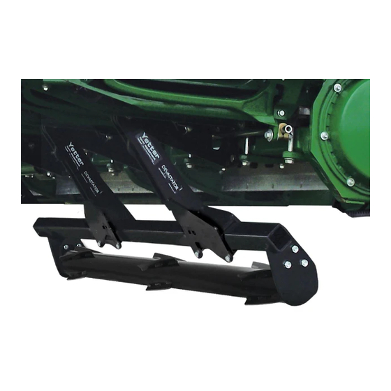
STALK DEVASTATOR™
John Deere All Chopping / 20", 22", & 30"
Geringhoff All Chopping / 20", 22", & 30"
All Lexion/Capello Non-Chopping
YETTER MANUFACTURING CO.
Founded 1930
Colchester, IL 62326
Toll free: (800)447-5777.
Fax: (309)776-3222
Website: yetterco.com
E-mail: info@yetterco.com
5000 SERIES
All Calmer
OWNER'S MANUAL
PART IDENTIFICATION
2565-965 ● 8/2019
Advertisement

Related Manuals for Yetter STALK DEVASTATOR 5000 Series


Summary of Contents for Yetter STALK DEVASTATOR 5000 Series
- Page 1 John Deere All Chopping / 20”, 22”, & 30” Geringhoff All Chopping / 20”, 22”, & 30” All Calmer All Lexion/Capello Non-Chopping OWNER’S MANUAL PART IDENTIFICATION 2565-965 ● 8/2019 YETTER MANUFACTURING CO. Founded 1930 Colchester, IL 62326 Toll free: (800)447-5777. Fax: (309)776-3222 Website: yetterco.com E-mail: info@yetterco.com...
- Page 2 WARRANTY Yetter Manufacturing warrants all products manufactured and sold by it against defects in material. This warranty being expressly limited to replacement at the factory of such parts or products as shall appear to be defective after inspection.
- Page 3 BE ALERT! YOUR SAFETY IS INVOLVED WATCH FOR THIS SYMBOL. IT POINTS OUT IMPORTANT SAFETY PRECAUTIONS. IT MEANS “ATTENTION – BE ALERT!” It is your responsibility as an owner, operator, or supervision to know and instruct everyone using this machine at the time of initial assignment and at least annually thereafter, of the proper operation, precautions, and work hazards which exist in the operation of the machine in accordance with OSHA regulations.
- Page 4 PLEASE READ, VERY IMPORTANT SECURE CORN HEADER AGAINST UNWANTED LOWERING BY APPLYING THE LOCKING MECHANISM ON THE HYDRAULIC CYLINDERS! 1. Attach head to combine, lock head to combine 2. Raise the head off the ground and engage safety stop on the feeder house cylinder.
- Page 5 BOLT TORQUE Important: Over-tightening hardware can cause just as much damage as under-tightening. Tightening hardware beyond the recommended range can reduce its shock load capacity. All hardware on the 5000 Devastator is either Grade 5 or Grade 8, unless otherwise noted. Grade 5 cap screws are marked with three radial lines on the head.
- Page 6 BILL OF MATERIALS PER KIT 5000-040A – 6R30 JD StalkMaster 606C/706C – 2) 5000-160 Roller Bearing Bolt Bag, 4) 5000-167 Torsion Pivot Assembly, 4) 5000- 168 Torsion Mount Bolt Bag, 2) 5000-272 3R30 Roller W.A., 2) 5000-275 4R20/3R30 Roller Mount W.A., 4) 5000-292 Torsion Arm W.A., 1) 5000-171 Manual Bag 5000-041A –...
- Page 7 NOTE: SUPPORT THE FRONT OF THE ROW UNIT BEFORE LOOSENING ANY MOUNTING HARDWARE. Step 1: Remove the mounting hardware for each gear box where the Yetter torsion pivot assembly will be mounted (see torsion pivot locations on pages 10 – 12 that match your devastator kit). Install the 5000-284 Calmer Adaptor Bracket on the bottom side of the frame sliding the threaded rod through each hole of the straps on the front of the frame and hand thread the 2502-397 5/8 –...
- Page 8 NOTE: SUPPORT THE FRONT OF THE ROW UNIT BEFORE LOOSENING ANY MOUNTING HARDWARE. Step 1: Remove the mounting hardware & strap for each gear box where the Yetter torsion pivot assembly will be mounted (see torsion pivot locations on pages 10 – 12 that match your devastator kit). Install the 5000-452 Lexion adaptor bracket on the bottom side of the frame using 4) 2502-813 M16 X 2 X 70 8.8 bolts, the original...
- Page 9 5000-072 ASSEMBLY INSTRUCTIONS NOTE: SUPPORT THE FRONT OF THE ROW UNIT BEFORE LOOSENING ANY MOUNTING HARDWARE. Step 1: (see torsion pivot locations on pages 10 – 12 that match your devastator kit). Place the 2) 5000-454 Spacers (longer, used on non-Horizon Geringhoff corn heads) OR 2) 5000-472 Spacers (shorter, used on Horizon Geringhoff corn heads) in the 5000-453 Geringhoff Adaptor Plate.
- Page 10 ASSEMBLY INSTRUCTIONS BELOW ARE RECOMMENDED LOCATIONS OF THE TORSION PIVOT ASSEMBLY, ALTERNATE LOCATIONS MAY BE USED IF INTERFERENCE OCCURS! 5000-040 6 ROW 30” Arrows indicate 5000-167 Torsion Pivot locations 5000-041 8 ROW 30” Arrows indicate 5000-167 Torsion Pivot locations 5000-042 12 ROW 20” Arrows indicate 5000-167 Torsion Pivot locations...
- Page 11 ASSEMBLY INSTRUCTIONS BELOW ARE RECOMMENDED LOCATIONS OF THE TORSION PIVOT ASSEMBLY, ALTERNATE LOCATIONS MAY BE USED IF INTERFERENCE OCCURS! 5000-043 1290 12 ROW 20” Arrows indicate 5000-167 Torsion Pivot locations 5000-044 12 ROW 30” Arrows indicate 5000-167 Torsion Pivot locations *On Rows 3 and 10, 1 set of M16 Bolts will thread into the gear box* 5000-045 18 ROW 20”...
- Page 12 ASSEMBLY INSTRUCTIONS BELOW ARE RECOMMENDED LOCATIONS OF THE TORSION PIVOT ASSEMBLY, ALTERNATE LOCATIONS MAY BE USED IF INTERFERENCE OCCURS! 5000-046 12 ROW 22” Arrows indicate 5000-167 Torsion Pivot locations 5000-047 18 ROW 22” Arrows indicate 5000-167 Torsion Pivot locations...
- Page 13 ASSEMBLY INSTRUCTIONS Step 1: Attach the 5000-167 torsion mount bracket to the frame using 4) M16 X 110 flange head bolts & 2) 5000-420 clamp straps. Thread the bolts into the clamp straps by hand & tighten to torque specifications. Note: Torque the M16 bolts @ 236 ft.
- Page 14 ASSEMBLY INSTRUCTIONS Step 2: Install the 5000-292 Torsion Arm onto the Torsion Pivot Assembly & secure with the ¾” x 8” bolts & ¾” lock nuts. Refer to the diagrams on the pages 10 – 12 to determine which side of the Torsion Pivot Assembly to install the 5000-292 Torsion Arm.
- Page 15 ASSEMBLY INSTRUCTIONS Step 4: Install the Devastator roller, spacer/bushing and bearings to the roller tube using the ½” x 2-1/2” carriage bolts. A 3R30 roller is pictured in the diagram below. IMPORTANT: The spacer must be installed between the roller and the bearing. The notches of the bearing housing must face the mounting plate.
- Page 16 ASSEMBLY INSTRUCTIONS Step 5: Slide the roller mount tubes to align the row center with the traction bars. Fully tighten hardware. In some circumstances, the traction bar may have to be off-center of the row some. Step 6: (If Applicable) On chopping corn heads, trim 3 inches off the bottom of the back curtain to keep the roller from contacting the curtain.
- Page 17 LOCK UP To “lock up” the Devastator rollers, lower the head down & install a rod through the hole in the mount bracket in front of the pivot arms. A 5000-430 Lock Pin can be ordered separately to lock up the devastator rollers. 6 row heads require 1 lock pin, 8/12 row heads require 2, 18 row heads require 3.
- Page 18 5000-040A PART IDENTIFICATIONS JD 606C/706C 6R30 ALL MODELS ITEM PART # DESCRIPTION QUANTITY 2502-430 ¾ - 10 X 8 HHCS GR 8 ZP 2502-805 M16 X 2 X 120 HEX FLANGE BOLT, THREADLOCK, ZP (USED ONLY IN GEAR BOXES) 2502-806 M16 X 2 X 110 HEX FLANGE BOLT, THREADLOCK, ZP ( USED ONLY IN 4”...
- Page 19 5000-041A PART IDENTIFICATIONS JD 608C/708C 8R30 ALL MODELS ITEM PART # DESCRIPTION QUANTITY 2502-430 ¾ - 10 X 8 HHCS GR 8 ZP 2502-805 M16 X 2 X 120 HEX FLANGE BOLT, THREADLOCK, ZP (USED ONLY IN GEAR BOXES) 2502-806 M16 X 2 X 110 HEX FLANGE BOLT, THREADLOCK, ZP ( USED ONLY IN 4”...
- Page 20 5000-042A & 5000-043A PART IDENTIFICATION JD 612C & 712C 12R20 ALL MODELS / 1290 12R20 ITEM PART # DESCRIPTION QUANTITY 2502-430 ¾ - 10 X 8 HHCS GR 8 ZP 2502-805 M16 X 2 X 120 HEX FLANGE BOLT, THREADLOCK, ZP (USED ONLY IN GEAR BOXES) 2502-806 M16 X 2 X 110 HEX FLANGE BOLT, THREADLOCK, ZP ( USED ONLY IN 4”...
- Page 21 5000-044A PART IDENTIFICATION JD 612C / 712C 12R30 ALL MODELS ITEM PART # DESCRIPTION QUANTITY 2502-430 ¾ - 10 X 8 HHCS GR 8 ZP 2502-805 M16 X 2 X 120 HEX FLANGE BOLT, THREADLOCK, ZP (USED ONLY IN GEAR BOXES) 2502-806 M16 X 2 X 110 HEX FLANGE BOLT, THREADLOCK, ZP ( USED ONLY IN 4”...
- Page 22 5000-045A PART IDENTIFICATION JD 618C / 718C 18R20 ALL MODELS ITEM PART # DESCRIPTION QUANTITY 2502-430 ¾ - 10 X 8 HHCS GR 8, ZP 2502-805 M16 X 2 X 120 HEX FLANGE BOLT, THREADLOCK, ZP (USED ONLY IN GEAR BOXES) 2502-806 M16 X 2 X 110 HEX FLANGE BOLT, THREADLOCK, ZP ( USED ONLY IN 4”...
- Page 23 5000-046A PART IDENTIFICATION JD 612C / 712C 12ROW22 ALL MODELS ITEM PART # DESCRIPTION QUANTITY 2502-430 ¾ - 10 X 8 HHCS GR 8 ZP 2502-805 M16 X 2 X 120 HEX FLANGE BOLT, THREADLOCK, ZP (USED ONLY IN GEAR BOXES) 2502-806 M16 X 2 X 110 HEX FLANGE BOLT, THREADLOCK, ZP ( USED ONLY IN 4”...
- Page 24 5000-047A PART IDENTIFICATION JD 618C / 718C 18ROW22 ALL MODELS ITEM PART # DESCRIPTION QUANTITY 2502-430 ¾ - 10 X 8 HHCS GR 8 ZP 2502-805 M16 X 2 X 120 HEX FLANGE BOLT, THREADLOCK, ZP (USED ONLY IN GEAR BOXES) 2502-806 M16 X 2 X 110 HEX FLANGE BOLT, THREADLOCK, ZP ( USED ONLY IN 4”...
- Page 25 5000-070 PART IDENTIFICATION ITEM PART # DESCRIPTION QUANTITY 2502-397 5/8 – 11 X 5 ½ HHCS GR 5 ZP 2502-809 M16 X 2 X 65 HEX FLANGE SCREW, THREAD LOCK, ZP 2502-810 M16 X 2 X 30 HEX FLANGE SCREW, THREAD LOCK, ZP 2520-452 5/8 –...
- Page 26 5000-071 PART IDENTIFICATION ITEM PART # DESCRIPTION QUANTITY 2502-810 M16 X 2 X 30 HEX FLANGE SCREW, THREAD LOCK, ZP 2502-813 M16 X 2 X 70 8.8 HHCS ZP 5000-452 CAPELLO/LEXION ADAPTER PLATE 5000-072 PART IDENTIFICATION ITEM PART # DESCRIPTION QUANTITY 2502-810 M16 X 2 X 30 HEX FLANGE SCREW, THREAD LOCK, ZP...
- Page 28 2565-965 – 08/2019...
Need help?
Do you have a question about the STALK DEVASTATOR 5000 Series and is the answer not in the manual?
Questions and answers