
Related Manuals for Yetter Systems One Seed Jet II


Summary of Contents for Yetter Systems One Seed Jet II
- Page 1 Systems One A YETTER COMPANY SEED JET II 2565-441_REV_D 02/2012 YETTER MANUFACTURING CO. FOUNDED 1930 Colchester, IL 62326-0358 Toll free: 800/447-5777 309/776-3222 (Fax) Website: www.yetterco.com E-mail: info@yetterco.com...
- Page 2 WARRANTY POLICY Yetter Manufacturing warrants all products manufactured and sold by it against defect in material. This warranty being expressly limited to replacement at the factory of such parts or products as shall appear to be defective after inspection. This warranty does not obligate the Company to bear cost of labor in replacement of parts.
-
Page 3: Table Of Contents
TABLE OF CONTENTS Cover Page…………………………………………………………………….. 1 Foreword……………………………………………………………………….. 2 Table of Contents……………………………………………………………… 3 Safety Information……………………………………………………………... 4 General Information…………………………………………………………… 5 Assembly Instructions 1300-183 Power Unit Assembly……….……………………………...6 1300-120 Hopper Assembly……………………………………….… 7 1300-124 Seed Jet II Hose Assembly………………………………8-9 Operation………………………………………………………………………..10 Maintenance…………………………………………………………………….11 Parts Identification 1300-121 Seed Jet II………………………………………………….12 1300-120 Hopper Assembly………………………………………….13 1300-119 Airlock Assembly…………………………………………..14 1300-183 Power Unit Assembly………………………………….15-22... - Page 4 SAFETY PRECAUTIONS You can make your farm a safer place to live and work if you observe the safety precautions given. Study these precautions carefully and insist those working with you and for you follow the precautions. Finally, remember this an accident is usually caused by someone’s carelessness, neglect or oversight. A brief description of signal words that may be used in this manual: CAUTION: Used as a general reminder of good safety practices or to direct attention to unsafe practices.
-
Page 5: General Information
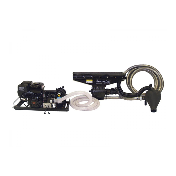
FAILURE TO HEED MAY RESULT IN PERSONAL INJURY OR DEATH. GENERAL INFORMATION SHIPMENT CHECKLIST Your Seed Jet II is shipped as a complete unit in one container. Please check that the following items are received in the container: Power Unit Assembly Hopper Assembly Bolt Bag, Seed Jet II Seed Jet II Hose Assembly... - Page 6 ASSEMBLY INSTRUCTIONS POWER UNIT SET UP 1. Add oil to blower gear case. DO NOT OVERFILL. 8 oz., 80W-140 gear oil (ISO220, 5EP, GL-5 service grade). Lubricate the bearings using Shell Darina EP NLG grade 2 grease. 2. Fill crankcase of engine with oil. (High quality SAE 30 weight, SE, SF or SG service grade) 3.
-
Page 7: Hopper Assembly
ASSEMBLY INSTRUCTIONS HOPPER UNIT SET UP With the assistance of another person and/or lifting equipment, position the hopper assembly next to the discharge slide door of your gravity wagon. The hopper should be level once attached. The brackets supplied are of a universal type and it may be necessary to drill extra holes in the frame of your wagon to attach these parts. - Page 8 ASSEMBLY INSTRUCTIONS 35’ SEED HOSE ASSEMBLY STEP 1. Attach the 1300-124 seed hose assembly to the 2 1/4” airlock fitting and secure with the 2570- 716 muffler style clamp. DO NOT OVER TIGHTEN THE CLAMP. STEP 2. Attach the 1300-166 cyclone exhaust kit to the seed cyclone. Left hand thread the 2515-712 hose cuff onto the 1300-553 3 1/8”...
- Page 9 ASSEMBLY INSTRUCTIONS STEP 3. Attach the 1300-163 cable assembly to the 1300-124 seed hose assembly. Connect the 1300- 163 cable to the power unit’s module at the plug connector labeled “switch input”. Inspect the plug connector for dirt, debris or bent pins; clean and repair the connectors if necessary. STEP 3.
-
Page 10: Operation
SYSTEM HOOK UP AND USE These instructions are to describe the typical set up of the Seed Jet II on a gravity flow wagon towed by a pickup truck. 1. Place power unit assembly in pickup bed and hitch truck to gravity wagon. 2. -
Page 11: Maintenance
MAINTENANCE WARNING: Never clean, lubricate or adjust a machine that is in motion. Failure to heed may result in serious personal injury or death. Inspect daily and clean safety decals. Replace if torn or no longer functional. Inspect daily the air cleaner element and clean or replace as required. Inspect daily and retighten, as required, all bolts on the power unit and assemblies. - Page 12 PARTS IDENTIFICATION...
- Page 13 PARTS IDENTIFICATION...
- Page 14 PARTS IDENTIFICATION...
- Page 15 PARTS IDENTIFICATION...
- Page 16 PARTS IDENTIFICATION PARTS IDENTIFICATION...
- Page 17 PARTS IDENTIFICATION...
- Page 18 PARTS IDENTIFICATION...
- Page 19 PARTS IDENTIFICATION...
- Page 20 PARTS IDENTIFICATION...
- Page 21 PARTS IDENTIFICATION...
- Page 22 PARTS IDENTIFICATION...
- Page 23 PARTS IDENTIFICATION 1300-124 SEED JET II HOSE ASSEMBLY Qty. Part No. Description 1300-376 Cyclone, Black 2570-721 Hose Clamp, SAE #44, Ideal 64,SS 2570-767 2” Conduit Hanger ZP w/Hardware 1300-596 2-1/4” ID x 35 Ft. Cotton Lined S.S. Hose 1300-549 Cyclone Bracket 2502-105 1/4-20 x 3/4 HHCS Gr.
- Page 24 PARTS IDENTIFICATION...
- Page 25 POWER UNIT WIRING DIAGRAM DISCONNECT ALL WIRES AT NEGATIVE TERMINAL OF 12 VOLT BATTERY FOR SAFETY WHILE SERVICING UNIT. OPTIONAL REMOTE TOGGLE SWITCH ASSEMBLY BREAKDOWN...
-
Page 26: Power Unit Assembly
TROUBLESHOOTING Problem Cause Solution Airlock will not turn on/off Replace frame mounted solenoid Frame mount relay not functioning Check output from alternator No voltage from alternator Check plug in on duplex wires Loose connections Check connections at 12v motor Check ground and solenoid connections Replace 25 amp round fuse Blown fuse... - Page 27 NOTES:...
- Page 28 East, the South, the West and now north into Canada. We’re even getting orders from as far away as Australia and Africa. So, when you buy Yetter products . . .you’re buying a name that’s recognized. A name that’s known and respected. A name that’s become a part of American agriculture and has become synonymous with quality and satisfaction in the field of conservation tillage.
Need help?
Do you have a question about the Systems One Seed Jet II and is the answer not in the manual?
Questions and answers
We are not getting the selinoid to transfer power to the motor. we jump the selinoid and everytthing works, Where do we look for a soluyioh
Possible causes for the solenoid not transferring power to the motor on the Yetter Seed Jet II include:
- Frame mount relay (solenoid) not functioning; it may need replacement.
- No voltage from the alternator.
- Loose connections at the duplex wires, 12V motor, ground, or solenoid.
- A blown 25 amp round fuse in the 1300-614 interface module.
This answer is automatically generated