Yetter 5000 SERIES Owner's Manual
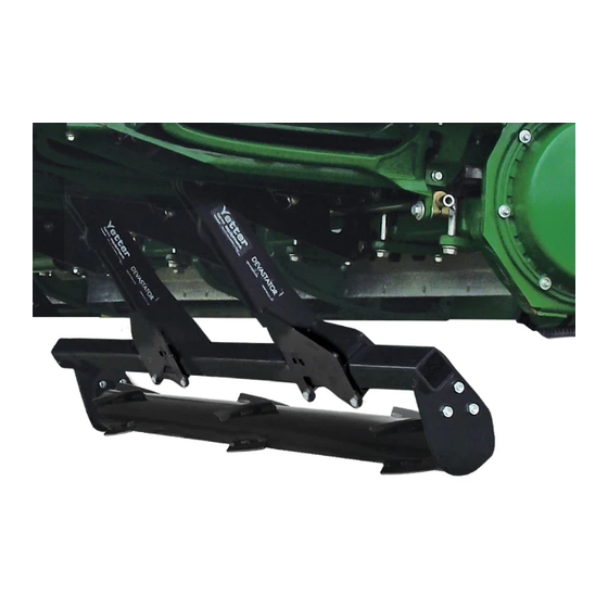
Stalk devastator. drago gt model corn heads
Hide thumbs
Also See for 5000 SERIES:
- Owner's manual (48 pages) ,
- Owner's manual & parts list (32 pages) ,
- Operator's manual (24 pages)

Related Manuals for Yetter 5000 SERIES


Summary of Contents for Yetter 5000 SERIES
- Page 1 5000 SERIES STALK DEVASTATOR DRAGO GT MODEL CORN HEADS OWNER’S MANUAL PART IDENTIFICATION 2565-969 06/2019 YETTER MANUFACTURING CO. Founded 1930 Colchester, IL 62326 Toll free: (800)447-5777. Fax: (309)776-3222 Website: yetterco.com E-mail: info@yetterco.com...
-
Page 2: Table Of Contents
WARRANTY Yetter Manufacturing warrants all products manufactured and sold by it against defects in material. This warranty being expressly limited to replacement at the factory of such parts or products as shall appear to be defective after inspection. - Page 3 BE ALERT! YOUR SAFETY IS INVOLVED WATCH FOR THIS SYMBOL. IT POINTS OUT IMPORTANT SAFETY PRECAUTIONS. IT MEANS “ATTENTION – BE ALERT!” It is your responsibility as an owner, operator, or supervision to know and instruct everyone using this machine at the time of initial assignment and at least annually thereafter, of the proper operation, precautions, and work hazards which exist in the operation of the machine in accordance with OSHA regulations.
- Page 4 PLEASE READ, VERY IMPORTANT SECURE CORN HEADER AGAINST UNWANTED LOWERING BY APPLYING THE LOCKING MECHANISM ON THE HYDRAULIC CYLINDERS! 1. Attach head to combine, lock head to combine 2. Raise the head off the ground and engage safety stop on the feeder house cylinder.
- Page 5 PLEASE READ, VERY IMPORTANT Subject to the size and weight of the corn header, one or two additional hydraulic cylinders may be required. The combine manufacturer generally keeps corresponding kits readily available for dealers. Subject to the design of the corn header and the carrying capacity of different combines, the steering axle may require the fitting of additional weights and the rear tires be filled with ballast.
-
Page 6: Torque
BOLT TORQUE Important: Over-tightening hardware can cause just as much damage as under-tightening. Tightening hardware beyond the recommended range can reduce its shock load capacity. All hardware on the 5000 Devastator is either Grade 5 or Grade 8, unless otherwise noted. Grade 5 cap screws are marked with three radial lines on the head. - Page 7 BILL OF MATERIALS PER KIT 5000-050A – 6R30 Drago GT – 2) 5000-160 Roller Bearing Bolt Bag, 4) 5000-169 Torsion Pivot Assembly, 4) 5000-170 Torsion Mount Bolt Bag, 2) 5000-272 3R30 Roller W.A., 2) 5000-275 4R20/3R30 Roller Mount W.A., 2) 5000-277 Torsion Mount W.A., 1) 5000-278 Drago GT Center Pivot W.A., 4) 5000-292 Torsion Arm W.A., 1) 5000-440 Center Backing Plate, 1) 5000-441 Short/Double Backing Plate, 1) 5000-172 Manual Bag 5000-051A –...
-
Page 8: Assembly Instructions
ASSEMBLY INSTRUCTIONS 5000-050A 6 ROW 30” Arrows indicate 5000-277 & 5000-278 mount bracket & 5000-169 torsion pivot locations 5000-051A 8 ROW 30” Arrows indicate 5000-277 & 5000-278 mount bracket & 5000-169 torsion pivot locations 5000-052A 12 ROW 30” Arrows indicate 5000-277 & 5000-278 mount bracket & 5000-169 torsion pivot locations... -
Page 9: Assembly Instructions
ASSEMBLY INSTRUCTIONS Step 1: Install the 5000-277 Torsion Mount and the 5000-5000-278 Center Pivot. The Torsion Mounts will each use 2) 5000- 438 Backing Plates and 2) 5000-439 Short Backing Plates. The Center Pivot will use 2) Backing Plates and 2) Short Backing Plates on the outer edges &... - Page 10 ASSEMBLY INSTRUCTIONS Step 2: Attach the 5000-169 torsion pivot assembly to the torsion mount and center pivot using 5/8 X 2 bolts and 5/8 lock hex nuts. Step 3: Attach the 5000-292 torsion arm to the torsion pivot assemblies. Place 1) 5000-469 security cap over the 2502- 322 ¾...
- Page 11 ASSEMBLY INSTRUCTIONS Step 5: Place each roller, 5000-268 2R30 (8 ROW ONLY) & 5000-272 3R30, into the circular cut out on the roller mount & turn the roller to keep the roller from dropping. Place the 5000-468 spacer over the square shaft on the roller. Place the 5000-355 bearing over the shaft so that the side of the bearing that sticks out beyond the housing faces away from the roller.
-
Page 12: Lock Up / Operation
LOCK UP To “lock up” the Devastator roller, install a rod through the hole in the mount bracket, in front of the pivot arms. A 5000-430 Lock Pin can be ordered to lock up the devastators. 6 row heads require 1 lock pin, 8/12 row heads require 2. OPERATION CORN HEAD ANGLE NEEDS TO BE ADJUSTED BETWEEN 23 –... - Page 13 5000-050A PART IDENTIFICATIONS DRAGO GT 6 ROW...
- Page 14 5000-050A PART IDENTIFICATIONS DRAGO GT 6 ROW ITEM PART # DESCRIPTION QUANTITY 5/8 – 11 X 2 HHCS GR 8 2502-322 2502-430 ¾ - 10 X 8 HHCS GR 8 ZP 3/8 – 16 X 1 ½ CARRIAGE BOLT GR 5 ZP 2505-262 2505-343 ½...
- Page 15 5000-051A PART IDENTIFICATIONS DRAGO GT 8 ROW...
- Page 16 5000-051A PART IDENTIFICATIONS DRAGO GT 8 ROW ITEM PART # DESCRIPTION QUANTITY 5/8 – 11 X 2 HHCS GR 8 2502-322 2502-430 ¾ - 10 X 8 HHCS GR 8 ZP 3/8 – 16 X 1 ½ CARRIAGE BOLT GR 5 ZP 2505-262 2505-343 ½...
-
Page 17: Part Identification
5000-052A PART IDENTIFICATION DRAGO GT 12 ROW... - Page 18 5000-050A PART IDENTIFICATIONS DRAGO GT 12 ROW ITEM PART # DESCRIPTION QUANTITY 5/8 – 11 X 2 HHCS GR 8 2502-322 2502-430 ¾ - 10 X 8 HHCS GR 8 ZP 3/8 – 16 X 1 ½ CARRIAGE BOLT GR 5 ZP 2505-262 2505-343 ½...
- Page 20 2565-969 – 06/2019...
Need help?
Do you have a question about the 5000 SERIES and is the answer not in the manual?
Questions and answers