Yetter 5000 Series Owner's Manual & Parts List
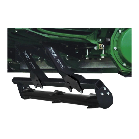
Stalk devastator
Hide thumbs
Also See for 5000 Series:
- Owner's manual (48 pages) ,
- Operator's manual (24 pages) ,
- Owner's manual, part identification (20 pages)
Advertisement
Quick Links
5000 SERIES STALK DEVASTATOR
John Deere Chopping / 20", 22", & 30"
Geringhoff Chopping / 20", 22", & 30"
Case 20" & 22" 2212 / 2412 / 3212 / 3412
New Holland 20" & 22" NH96C / 996 / 98D
Calmer / Lexion & Capello Non-Chopping
OWNER'S MANUAL & PART IDENTIFICATION
YETTER MANUFACTURING CO.
Founded 1930
Colchester, IL 62326
Toll free: (800)447-5777.
Fax: (309)776-3222
Website: yetterco.com
E-mail: info@yetterco.com
2565-965_REV_A ● 06/2020
Advertisement

Related Manuals for Yetter 5000 Series


Summary of Contents for Yetter 5000 Series
- Page 1 5000 SERIES STALK DEVASTATOR John Deere Chopping / 20”, 22”, & 30” Geringhoff Chopping / 20”, 22”, & 30” Case 20” & 22” 2212 / 2412 / 3212 / 3412 New Holland 20” & 22” NH96C / 996 / 98D Calmer / Lexion &...
-
Page 2: Table Of Contents
E-mail: info@yetterco.com WARRANTY Yetter Manufacturing warrants all products manufactured and sold by it against defects in material. This warranty being expressly limited to replacement at the factory of such parts or products as shall appear to be defective after inspection. - Page 3 BE ALERT! YOUR SAFETY IS INVOLVED WATCH FOR THIS SYMBOL. IT POINTS OUT IMPORTANT SAFETY PRECAUTIONS. IT MEANS “ATTENTION – BE ALERT!” It is your responsibility as an owner, operator, or supervision to know and instruct everyone using this machine at the time of initial assignment and at least annually thereafter, of the proper operation, precautions, and work hazards which exist in the operation of the machine in accordance with OSHA regulations.
- Page 4 PLEASE READ, VERY IMPORTANT SECURE CORN HEADER AGAINST UNWANTED LOWERING BY APPLYING THE LOCKING MECHANISM ON THE HYDRAULIC CYLINDERS! 1. Attach head to combine, lock head to combine 2. Raise the head off the ground and engage safety stop on the feeder house cylinder.
- Page 5 DEVASTATOR OPERATION CHECKLIST Please fill this out after the Yetter Stalk Devastator has been installed. DATE____/____/____ YETTER KIT # - 5000-____ CORN HEAD MAKE/MODEL___________________ COMBINE MAKE/MODEL__________________ FRONT TIRE SIZE______________ REAR TIRE SIZE______________ REAR AXLE POSITION______________ SNAPPING ROLLS USING______________ CHOPPING BLADES YES / NO DECK PLATE ANGLE_____°...
- Page 6 BILL OF MATERIALS PER KIT 5000-040B – 6R30 JD StalkMaster 606C/706C – 2) 5000-160A Roller Bearing Bolt Bag, 4) 5000-167 Torsion Pivot Assembly, 4) 5000-168 Torsion Mount Bolt Bag, 1) 5000-171 Manual Bag, 2) 5000-272 3R30 Roller W.A., 2) 5000-275A 4R20/3R30 Roller Mount W.A., 4) 5000-292 Torsion Arm W.A. 5000-040GER –...
- Page 7 DIFFERENT MOUNT LOCATIONS MAY BE NECESSARY IF CLEARANCE ISSUES ARE FOUND. Step 1: Remove the mounting hardware for each gear box where the Yetter torsion pivot assembly will be mounted (see torsion pivot locations on pages 10 – 11 that match your devastator kit). Install the 5000-284 Calmer Adaptor Bracket on the bottom side of the frame sliding the threaded rod through each hole of the straps on the front of the frame and hand thread the 2502-397 5/8 –...
- Page 8 DIFFERENT MOUNT LOCATIONS MAY BE NECESSARY IF CLEARANCE ISSUES ARE FOUND. Step 1: Remove the mounting hardware & strap for each gear box where the Yetter torsion pivot assembly will be mounted (see torsion pivot locations on pages 10 – 11 that match your devastator kit). Install the 5000-452 Lexion adaptor bracket on the bottom side of the frame using 4) 2502-813 M16 X 2 X 70 8.8 bolts, the original flat...
- Page 9 5000-072 ASSEMBLY INSTRUCTIONS GERINGHOFF NOTE: GEAR BOXES MUST BE USED TO MOUNT TORSION PIVOTS. SUPPORT THE FRONT OF ROW UNIT BEFORE LOOSENING ANY MOUNTING HARDWARE. DIFFERENT MOUNT LOCATIONS MAY BE NECESSARY IF CLEARANCE ISSUES ARE FOUND (see torsion pivot locations on pages 10 – 11 that match your devastator kit). Place the 2) 5000-454 Spacers (longer, used on non- Step 1: Horizon Geringhoff corn heads) OR 2) 5000-472 Spacers (shorter, used on Horizon Geringhoff corn heads) in the 5000-453 Geringhoff Adaptor Plate.
-
Page 10: Assembly Instructions
ASSEMBLY INSTRUCTIONS BELOW ARE RECOMMENDED LOCATIONS OF THE TORSION PIVOT ASSEMBLY, ALTERNATE LOCATIONS MAY BE USED IF INTERFERENCE OCCURS! 5000-040 & 5000-040GER 6 ROW 30” Arrows indicate 5000-167/5000-174 Torsion Pivot locations – Geringhoff models must use a gearbox 5000-041 & 5000-041GER 8 ROW 30” Arrows indicate 5000-167/5000-174 Torsion Pivot locations –... - Page 11 ASSEMBLY INSTRUCTIONS BELOW ARE RECOMMENDED LOCATIONS OF THE TORSION PIVOT ASSEMBLY, ALTERNATE LOCATIONS MAY BE USED IF INTERFERENCE OCCURS! 5000-045 & 5000-045GER 18 ROW 20” Arrows indicate 5000-167/5000-174 Torsion Pivot locations – Geringhoff models must use a gearbox 5000-046, 5000-046CNHA, & 5000-046GER 12 ROW 22” Arrows indicate 5000-167/5000-174 Torsion Pivot locations –...
- Page 12 ASSEMBLY INSTRUCTIONS – CASE & NEW HOLLAND Step 1: Attach the 5000-167 torsion mount bracket to the frame using 2) ½ X 4 ½” bolts w/ torque patch & 2) 9/16ID X 1 3/4OD X ¼ thick washers on the front side & 2) ½ X 6 ½ bolts with torque patch & 2) 9/16ID X 1 3/4OD X ¼ thick washers on the back side.
- Page 13 ASSEMBLY INSTRUCTIONS Step 3: Install the 5000-292 Torsion Arm onto the Torsion Pivot Assembly & secure with the ¾” x 8” bolts & ¾” lock nuts. Refer to the diagrams on the pages 10 – 12 to determine which side of the Torsion Pivot Assembly to install the 5000-292 Torsion Arm.
- Page 14 ASSEMBLY INSTRUCTIONS Step 4: Insert the shim washer over the shaft on each end of the roller. Install the bearing over the shaft on each end of the roller so that the side of the casting that has the bearing protruding past the housing surface is towards the roller barrel &...
-
Page 15: Lock Up / Operation
LOCK UP To “lock up” Devastator rollers, lower head down & install a rod through hole in mount bracket in front of pivot arms. A 5000- 430 Lock Pin can be ordered separately to lock up devastator rollers. 6 row heads require 1 lock pin, 8/12 row heads require 2, 18 row heads require 3. -
Page 16: Storage / Transport / Maintenance
STORAGE/TRANSPORT Head cart may need adjusted to fit the head with devastator correctly. E.g. raising or fore/aft adjustment of saddles/top rail on the head cart. If head cart does not have these adjustments, adding a tube extension to top rail or adding extension to saddle/corn head may be required. Side to side tilt may need used to clear taller head cart tires or locking the devastator up. - Page 17 5000-040B & 5000-040GER PART IDENTIFICATIONS JD 606C/706C/C6R & GERINGHOFF 6R30 MODELS ITEM PART # DESCRIPTION QUANTITY 2502-353 ½ - 13 X 2 ½ HHCS GR 8 ZP 2502-430 ¾ - 10 X 8 HHCS GR 8 ZP 2502-805 M16 X 2 X 120 HEX FLANGE BOLT, THREADLOCK, ZP (USED ONLY IN GEAR BOXES) M16 X 2 X 110 HEX FLANGE BOLT, THREADLOCK, ZP ( USED ONLY IN 4”...
- Page 18 5000-041B & 5000-041GER PART IDENTIFICATIONS JD 608C/708C/C8R & GERINGHOFF 8R30 MODELS ITEM PART # DESCRIPTION QUANTITY 2502-353 ½ - 13 X 2 ½ HHCS GR 8 ZP 2502-430 ¾ - 10 X 8 HHCS GR 8 ZP 2502-805 M16 X 2 X 120 HEX FLANGE BOLT, THREADLOCK, ZP (USED ONLY IN GEAR BOXES) M16 X 2 X 110 HEX FLANGE BOLT, THREADLOCK, ZP ( USED ONLY IN 4”...
- Page 19 5000-042B & 5000-042GER PART IDENTIFICATION JD 1290/612C/712C/C12R & GERINGHOFF 12R20 MODELS ITEM PART # DESCRIPTION QUANTITY 2502-353 ½ - 13 X 2 ½ HHCS GR 8 ZP 2502-430 ¾ - 10 X 8 HHCS GR 8 ZP 2502-805 M16 X 2 X 120 HEX FLANGE BOLT, THREADLOCK, ZP (USED ONLY IN GEAR BOXES) M16 X 2 X 110 HEX FLANGE BOLT, THREADLOCK, ZP ( USED ONLY IN 4”...
- Page 20 5000-042CNHA PART IDENTIFICATION CNH 2212, 2412, 3412 & NH 96C, 996, & NH98D 12R20 MODELS ITEM PART # DESCRIPTION QUANTITY 2502-279 ½ - 13 X 4 ½ GR 5 ZN, TORQ-PATCH 2502-353 ½ - 13 X 2 ½ HHCS GR 8 ZP 2502-359 ½...
- Page 21 5000-044B & 5000-044GER PART IDENTIFICATION JD 1293/612C/712C/C12F/C12R & GERINGHOFF 12R30 MODELS ITEM PART # DESCRIPTION QUANTITY 2502-353 ½ - 13 X 2 ½ HHCS GR 8 ZP 2502-430 ¾ - 10 X 8 HHCS GR 8 ZP 2502-805 M16 X 2 X 120 HEX FLANGE BOLT, THREADLOCK, ZP (USED ONLY IN GEAR BOXES) M16 X 2 X 110 HEX FLANGE BOLT, THREADLOCK, ZP ( USED ONLY IN 4”...
- Page 22 5000-045B & 5000-045GER PART IDENTIFICATION JD 618C/718C/C18F/C18R & GERINGHOFF 18R20 MODELS ITEM PART # DESCRIPTION QUANTITY 2502-353 ½ - 13 X 2 ½ HHCS GR 8 ZP 2502-430 ¾ - 10 X 8 HHCS GR 8, ZP 2502-805 M16 X 2 X 120 HEX FLANGE BOLT, THREADLOCK, ZP (USED ONLY IN GEAR BOXES) M16 X 2 X 110 HEX FLANGE BOLT, THREADLOCK, ZP ( USED ONLY IN 4”...
- Page 23 5000-046B & 5000-046GER PART IDENTIFICATION JD 612C/712C/C12R & GERINGHOFF 12R22 MODELS ITEM PART # DESCRIPTION QUANTITY ½ - 20 X 2 1/2” 2502-353 2502-430 ¾ - 10 X 8 HHCS GR 8 ZP 2502-805 M16 X 2 X 120 HEX FLANGE BOLT, THREADLOCK, ZP (USED ONLY IN GEAR BOXES) M16 X 2 X 110 HEX FLANGE BOLT, THREADLOCK, ZP ( USED ONLY IN 4”...
- Page 24 5000-046CNHA PART IDENTIFICATION CNH 2212, 2412, 3412 & NH 96C, 996, & NH98D 12R22 MODELS ITEM PART # DESCRIPTION QUANTITY 2502-279 ½ - 13 X 4 ½ GR 5 ZN, TORQ-PATCH 2502-353 ½ - 13 X 2 ½ HHCS GR 8 ZP 2502-359 ½...
- Page 25 5000-047B & 5000-047GER PART IDENTIFICATION JD 618C/718C/C18F/C18R & GERINGHOFF 18R22 MODELS ITEM PART # DESCRIPTION QUANTITY ½” – 13 x 2 ½ HHCS GR 8 ZP 2502-353 2502-430 ¾ - 10 X 8 HHCS GR 8 ZP 2502-805 M16 X 2 X 120 HEX FLANGE BOLT, THREADLOCK, ZP (USED ONLY IN GEAR BOXES) M16 X 2 X 110 HEX FLANGE BOLT, THREADLOCK, ZP ( USED ONLY IN 4”...
- Page 26 5000-070 PART IDENTIFICATION JD 90/40 SERIES / CALMER – ADAPTOR ITEM PART # DESCRIPTION QUANTITY 5/8 – 11 X 5 ½ HHCS GR 5 ZP 2502-397 2502-809 M16 X 2 X 65 HEX FLANGE SCREW, THREAD LOCK, ZP 2502-810 M16 X 2 X 30 HEX FLANGE SCREW, THREAD LOCK, ZP 5/8 –...
- Page 27 5000-071 PART IDENTIFICATION LEXION & CAPELLO – ADAPTOR ITEM PART # DESCRIPTION QUANTITY 2502-810 M16 X 2 X 30 HEX FLANGE SCREW, THREAD LOCK, ZP 2502-813 M16 X 2 X 70 8.8 HHCS ZP 5000-452 CAPELLO/LEXION ADAPTER PLATE...
- Page 28 5000-072 PART IDENTIFICATION GERINGHOFF ADAPTOR ITEM PART # DESCRIPTION QUANTITY 2502-810 M16 X 2 X 30 HEX FLANGE SCREW, THREAD LOCK, ZP 2502-814 M16 X 2 X 160 8.8 HHCS ZP 2502-815 M16 X 2 X 140 8.8 HHCS ZP 2502-817 M16 X 2 X 180 8.8 HHCS ZP 5000-174...
-
Page 29: Troublshooting
TROUBLSHOOTING ISSUE CAUSE CORRECTIVE ACTION 1. Adjust head angle to 23 – 25 degrees (see page 15) Residue Plugging 1. Incorrect Head Angle or wrapping 2. Roller Mount Tube 2. Make sure the Bearing Support Tab is on the backside incorrectly installed of the Roller Arm Mount Tube 3. - Page 32 2565-965_REV_A – 06/2020...
Need help?
Do you have a question about the 5000 Series and is the answer not in the manual?
Questions and answers