Yetter 5000 Series Owner's Manual
Stalk devastator, drago gt model corn heads
Hide thumbs
Also See for 5000 Series:
- Owner's manual (48 pages) ,
- Owner's manual & parts list (32 pages) ,
- Operator's manual (24 pages)
Advertisement
Quick Links
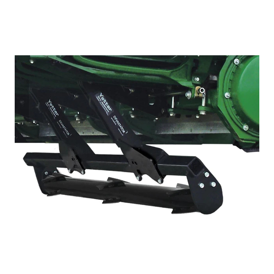
5000 SERIES STALK DEVASTATOR
DRAGO GT MODEL CORN HEADS
YETTER MANUFACTURING CO.
Founded 1930
Colchester, IL 62326
Toll free: (800)447-5777.
Fax: (309)776-3222
Website: yetterco.com
E-mail: info@yetterco.com
OWNER'S MANUAL
PART IDENTIFICATION
2565-969_REV_A ● 08/2020
Advertisement

Related Manuals for Yetter 5000 Series


Summary of Contents for Yetter 5000 Series
- Page 1 5000 SERIES STALK DEVASTATOR DRAGO GT MODEL CORN HEADS OWNER’S MANUAL PART IDENTIFICATION 2565-969_REV_A ● 08/2020 YETTER MANUFACTURING CO. Founded 1930 Colchester, IL 62326 Toll free: (800)447-5777. Fax: (309)776-3222 Website: yetterco.com E-mail: info@yetterco.com...
- Page 2 Website: www.yetterco.com E-mail: info@yetterco.com Yetter Manufacturing warrants all products manufactured and sold by it against defects in material. This warranty being expressly limited to replacement at the factory of such parts or products as shall appear to be defective after inspection.
- Page 3 BE ALERT! YOUR SAFETY IS INVOLVED WATCH FOR THIS SYMBOL. IT POINTS OUT IMPORTANT SAFETY PRECAUTIONS. IT MEANS “ATTENTION – BE ALERT!” It is your responsibility as an owner, operator, or supervision to know and instruct everyone using this machine at the time of initial assignment and at least annually thereafter, of the proper operation, precautions, and work hazards which exist in the operation of the machine in accordance with OSHA regulations.
- Page 4 PLEASE READ, VERY IMPORTANT SECURE CORN HEADER AGAINST UNWANTED LOWERING BY APPLYING THE LOCKING MECHANISM ON THE HYDRAULIC CYLINDERS! 1. Attach head to combine, lock head to combine 2. Raise the head off the ground and engage safety stop on the feeder house cylinder.
- Page 5 PLEASE READ, VERY IMPORTANT Subject to the size and weight of the corn header, one or two additional hydraulic cylinders may be required. The combine manufacturer generally keeps corresponding kits readily available for dealers. Subject to the design of the corn header and the carrying capacity of different combines, the steering axle may require the fitting of additional weights and the rear tires be filled with ballast.
- Page 6 DEVASTATOR OPERATION CHECKLIST Please fill this out after the Yetter Stalk Devastator has been installed. DATE____/____/____ YETTER KIT # - 5000-____ CORN HEAD MAKE/MODEL___________________ COMBINE MAKE/MODEL__________________ FRONT TIRE SIZE______________ REAR TIRE SIZE______________ REAR AXLE POSITION______________ SNAPPING ROLLS USING______________ CHOPPING BLADES YES / NO DECK PLATE ANGLE_____°...
- Page 7 BILL OF MATERIALS PER KIT 5000-050B – 6R30 Drago GT – 2) 5000-160A Roller Bearing Bolt Bag, 4) 5000-169 Torsion Pivot Assembly, 4) 5000-170 Torsion Mount Bolt Bag, 1) 5000-172 Manual Bag, 2) 5000-272 3R30 Roller, 2) 5000-275A 4R20/3R30 Roller Mount, 2) 5000-277 Torsion Mount, 1) 5000-278 Drago GT Center Pivot, 4) 5000-292 Torsion Arm, 1) 5000-440 Center Backing Plate, 1) 5000-441 Short/Double Backing Plate 5000-051B –...
- Page 8 ASSEMBLY INSTRUCTIONS **DUAL CHOPPING HEADS ARE NOT COMPATIBLE** 5000-050B 6 ROW 30” Arrows indicate 5000-277 & 5000-278 mount bracket & 5000-169 torsion pivot locations 5000-051B 8 ROW 30” Arrows indicate 5000-277 & 5000-278 mount bracket & 5000-169 torsion pivot locations...
- Page 9 ASSEMBLY INSTRUCTIONS **DUAL CHOPPING HEADS ARE NOT COMPATIBLE** 5000-052B 12 ROW 30” Arrows indicate 5000-277 & 5000-278 mount bracket & 5000-169 torsion pivot locations 5000-053A 16 ROW 30”...
- Page 10 ASSEMBLY INSTRUCTIONS Step 1: Attach each 5000-169 torsion pivot to each torsion mount & center pivot using 5/8” X 2” bolts & 5/8 lock hex nuts. Step 2: Install the 5000-277 & 5000-298 (16 row only) Torsion Mount & the 5000-5000-278 Center Pivot. The Torsion Mounts will each use 2) 5000-438 Backing Plates &...
- Page 11 ASSEMBLY INSTRUCTIONS Step 3: Attach 5000-292 torsion arm to each torsion pivot assembly. Place 1) 5000-469 security cap over 2502-322 ¾ X 8 bolt, slide bolt with cap through the torsion arm and torsion pivot, slide the 5000-468 spacer over bolt followed by another security cap, and then fasten the 2520- 604 ¾...
- Page 12 ASSEMBLY INSTRUCTIONS Step 6: Slide the roller mount tubes to align the row center with the traction bars. Fully tighten all hardware at this time to torque spec. The traction bars DO NOT have to be directly centered under each row. LOCK UP To “lock up”...
- Page 13 STORAGE/TRANSPORT Head cart may need adjusted to fit the head with devastator correctly. E.g. raising or fore/aft adjustment of saddles/top rail on the head cart. If head cart does not have these adjustments, adding a tube extension to top rail or adding extension to saddle/corn head may be required. Side to side tilt may need used to clear taller head cart tires or locking the devastator up.
- Page 14 5000-050B PART IDENTIFICATIONS DRAGO GT 6 ROW...
- Page 15 5000-050B PART IDENTIFICATIONS DRAGO GT 6 ROW ITEM PART # DESCRIPTION QUANTITY 2502-322 5/8 – 11 X 2 HHCS GR 8 2502-353 ½ - 13 X 2 ½ HHCS GR 8 ZP 2502-430 ¾ - 10 X 8 HHCS GR 8 ZP 2505-262 3/8 –...
- Page 16 5000-051B PART IDENTIFICATIONS DRAGO GT 8 ROW...
- Page 17 5000-051B PART IDENTIFICATIONS DRAGO GT 8 ROW ITEM PART # DESCRIPTION QUANTITY 2502-322 5/8 – 11 X 2 HHCS GR 8 2502-353 ½ - 13 x 2 ½ HHCS GR 8 ZP 2502-430 ¾ - 10 X 8 HHCS GR 8 ZP 2505-262 3/8 –...
- Page 18 5000-052B PART IDENTIFICATION DRAGO GT 12 ROW...
- Page 19 5000-052B PART IDENTIFICATIONS DRAGO GT 12 ROW ITEM PART # DESCRIPTION QUANTITY 2502-322 5/8 – 11 X 2 HHCS GR 8 2502-353 ½ - 13 X 2 ½ HHCS GR 8 ZP 2502-430 ¾ - 10 X 8 HHCS GR 8 ZP 2505-262 3/8 –...
- Page 20 5000-053A PART IDENTIFICATIONS...
- Page 21 5000-053A PART IDENTIFICATIONS ITEM PART # DESCRIPTION QUANTITY 2502-322 5/8 – 11 X 2 HHCS GR 8 2502-353 ½ - 13 X 2 ½ HHCS GR 8 ZP 2502-430 ¾ - 10 X 8 HHCS GR 8 ZP 2505-262 3/8 – 16 X 1 ½ CARRIAGE BOLT GR 5 ZP 2520-258 3/8 –...
- Page 22 TROUBLESHOOTING ISSUE CAUSE CORRECTIVE ACTION Residue Plugging 1. Incorrect Head Angle 1. Adjust head angle to 22 – 25 degrees (see page 12) 2. Roller Mount Tube 2. Make sure the Bearing Support Tab is on the backside incorrectly installed of the Roller Mount Tube 3.
- Page 23 2019 MODEL DEVASTATOR SHOWN...
- Page 24 2565-969_REV_A – 08/2020...
Need help?
Do you have a question about the 5000 Series and is the answer not in the manual?
Questions and answers