Table of Contents
Advertisement
Quick Links
PROPER USE GUIDELINES
Cumulative Trauma Disorders can result from the prolonged use of manually powered hand tools. Hand tools are intended for occasional use and low volume
applications. A wide selection of powered application equipment for extended-use, production operations is available.
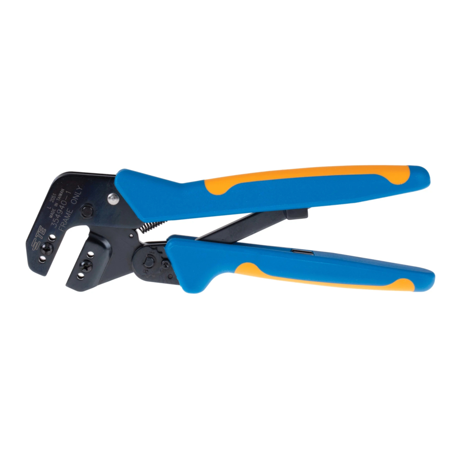
Crimper Die
(Stationary)
Anvil Die
(Movable)
1. INTRODUCTION
This instruction sheet provides application and
maintenance procedures for PRO–CRIMPER III Hand
Tool Assembly 58551–1 and Crimping Die Assembly
58552–1. See Figure 1. The hand tool consists of the
die assembly and PRO–CRIMPER III Hand Tool
Frame Assembly 58532–1, and crimps STC Fiber
Optic Connectors. The die assembly can be
purchased separately, or purchased with the hand
tool.
The information on connector part numbers and
connector assembly procedures, refer to the
appropriate instruction sheet packaged with the
connector.
All dimensions in this document are in millimeters
NOTE
[with inches in brackets]. Figures and Illustrations
are for reference only and are not drawn to scale.
i
Refer to Instruction Sheet 408–4020 for information
concerning the use and maintenance of Hand Tool
Frame Assembly 58532–1. Read these and all
referenced materials before using the die assemblies.
E
2009 Tyco Electronics Corporation, Harrisburg, PA
All International Rights Reserved
TE logo and Tyco Electronics are trademarks.
*Trademark. Other products, logos, and company names used are the property of their respective owners.
PRO-CRIMPER* III Hand
Tool Assembly 58551-1
and Die Assembly 58552-1
Crimping Die
Assembly 58552-1
Figure 1
Reasons for reissue are provided in Section 7,
REVISION SUMMARY.
2. DESCRIPTION
The die assembly features an anvil die and a crimper
die. When closed, the dies produce four crimping
chambers that crimp the ferrule of the connector onto
the fiber–optic cable. Each die is held in the tool jaws
with a single die–retaining screw. See Figure 2.
3. DIE INSTALLATION
TOOLING ASSISTANCE CENTER 1-800-722-1111
PRODUCT INFORMATION 1-800-522-6752
PRO-CRIMPER III
Frame Assembly
58532-1
(Figure 2)
1. Close the tool handles until the ratchet releases;
then allow the tool handles to open FULLY.
2. Install anvil die in the moving jaw of the hand
tool. Align the die with the retaining screw hole;
then secure die with the button head cap screw. Do
NOT fully tighten.
3. Install crimper die in the stationary jaw of the
hand tool. Slowly close the tool handles, allowing
the die to align itself with the upper die. When dies
are properly aligned, securely tighten both screws.
This controlled document is subject to change.
For latest revision and Regional Customer Service,
www.tycoelectronics.com
visit our website at
Instruction Sheet
408-4090
16 JAN 09
Rev A
1
of 3
LOC B
Advertisement
Table of Contents

Related Manuals for Tyco Electronics PRO-CRIMPER III


Summary of Contents for Tyco Electronics PRO-CRIMPER III
- Page 1 For latest revision and Regional Customer Service, All International Rights Reserved www.tycoelectronics.com visit our website at TE logo and Tyco Electronics are trademarks. LOC B *Trademark. Other products, logos, and company names used are the property of their respective owners.
- Page 2 408-4090 PRO-CRIMPER III Hand Tool Assembly 58551-1 Stationary Jaw Crimper Die (Stationary) Die Retaining Screws Anvil Die (Movable) Moving Ratchet Figure 2 4. CRIMPING PROCEDURE 2. Make certain that all die–retaining screws and (Figure 3) die components are properly secured.
- Page 3 408-4090 PRO-CRIMPER III Hand Tool Assembly 58551-1 higher–numbered setting. If a looser crimp is Screwdriver required, rotate the adjustment wheel CLOCKWISE to a lower–numbered setting. 4. Replace the lockscrew. 5. Make a sample crimp and measure the crimp height. If the crimp is acceptable, replace and secure the lockscrew.
Need help?
Do you have a question about the PRO-CRIMPER III and is the answer not in the manual?
Questions and answers