
Subscribe to Our Youtube Channel
Related Manuals for Thermo Scientific Dionex AutoTrace 280

Summary of Contents for Thermo Scientific Dionex AutoTrace 280
- Page 1 Dionex AutoTrace 280 SPE Instrument Operator’s Manual Document No. 065330 Revision 05 March 2020...
- Page 2 Revision 03 released May 2013; new system part numbers, Dionex SolEx cartridges, Windows 7 support Revision 04 released November 2013; new operating altitude specification Revision 05, released March 2020; Dionex AutoTrace 280 PFAS support For Research Use Only. Not for use in diagnostic procedures.
-
Page 3: Table Of Contents
Instruments ......... 6 1.4.2 Notice on the Proper Use of Thermo Scientific Instruments . . . 7 1.4.3 Notice on the Susceptibility to Electromagnetic Transmission . - Page 4 Loading a Method ......... .50 Preparing the Dionex AutoTrace 280 ......51 Running a Method .
- Page 5 Error Messages ......... . . 67 Dionex AutoTrace 280 Diagnostic Methods ..... 70 General Operation Troubleshooting .
- Page 6 Converting a Cartridge Holder (Standard Dionex AutoTrace 280) ..96 Converting a Cartridge Holder (Dionex AutoTrace 280 PFAS) ..99 Cleaning a Sample Pump Cylinder and Piston ....101 5.10 Calibrating a Sample Pump .
- Page 7 Facility Requirements ........127 Unpacking the Dionex AutoTrace 280 ......127 Installation Instructions .
- Page 8 Dionex AutoTrace 280 Operator’s Manual C • Reordering Information ......145 D • Glossary .
-
Page 9: Introduction
PFAS (per- and polyfluoroalkyl) from drinking water. Unless otherwise stated, information in this manual applies to both the standard and PFAS systems. The Dionex AutoTrace 280 is available in both cartridge and disk models: • Cartridge models use SPE devices in the cartridge format. Polymer cartridges are available in the following sizes: 1 mL, 3 mL, and 6 mL. - Page 10 Dionex AutoTrace 280 Sample Cleanup Kit (Option) The Dionex AutoTrace 280 Sample Cleanup Kit (P/N 083614) provides all the parts required to plumb the standard Dionex AutoTrace 280 for the extraction of nitrosamine compounds in water. This ensures that the Dionex AutoTrace 280 meets the needs of regulatory methods such as U.S.
-
Page 11: About This Manual
1 • Introduction AutoTrace 280 and the PC, the Dionex AutoTrace 280 must be connected to a USB (Universal Serial Bus) 2.0 port on the PC. NOTE If you connect the USB cable to a USB 3.0 port, the system will not operate correctly. -
Page 12: Safety Information
355 River Oaks Parkway, San Jose, CA 95134-1991 U.S.A. The Dionex AutoTrace 280 is designed to perform solid-phase extraction water methods. Operation of a Dionex AutoTrace 280 in a manner not specified by Thermo Fisher Scientific may result in personal injury. - Page 13 1 • Introduction Messages d’avertissement en français Signale une situation de danger immédiat qui, si elle n'est pas évitée, entraînera des blessures graves à mortelles. Signale une situation de danger potentiel qui, si elle n'est pas évitée, pourrait entraîner des blessures graves à mortelles. Signale une situation de danger potentiel qui, si elle n'est pas évitée, pourrait entraîner des blessures mineures à...
-
Page 14: Regulatory Compliance
EMC Specifications: EN 61326-1:2013 • RoHS Specifications: EN 50581:2012 The CE mark on the Dionex AutoTrace 280 model/data label indicates that it is in compliance with the following European Union (EU) Directives as is evidenced by compliance to the associated standard where appropriate: •... -
Page 15: Notice On The Proper Use Of Thermo Scientific Instruments
1 • Introduction 1.4.2 Notice on the Proper Use of Thermo Scientific Instruments In compliance with international regulations: This instrument must be used in the manner specified by Thermo Fisher Scientific to ensure protections provided by the instrument are not impaired. Deviations from specified instructions on the proper use of the instrument include changes to the system and parts replacement. - Page 16 Dionex AutoTrace 280 Operator’s Manual Conformité DEEE Ce produit est conforme avec la directive européenne (2012/19/EU) des Déchets d'Equipements Electriques et Electroniques (DEEE). Il est marqué par le symbole suivant: Ce symbole indique que l'équipement ne doit pas être jeté avec les déchets ordinaires, mais doit être collecté...
-
Page 17: Description
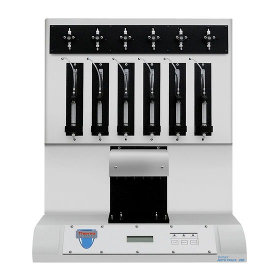
2 • Description Operating Features Figure 2-1 illustrates the main operating features on the front of the Dionex AutoTrace 280. Figure 2-1. Dionex AutoTrace 280 Front View (Cartridge Model) Part Function Sample Pumps Pumps sample from sample containers to switching valves. -
Page 18: Front Panel Controls
(see Figure 2-4). Front Panel Communicates system status to the user. 2.1.1 Front Panel Controls Figure 2-2 illustrates the Dionex AutoTrace 280 front panel LEDs and keypad. READY ERROR LOAD PAUSE CONT Figure 2-2. Front Panel Controls... -
Page 19: Front Panel Display Screen
2.1.2 Front Panel Display Screen The Dionex AutoTrace 280 front panel LCD (or screen) displays status and operating information. When the Dionex AutoTrace 280 power is turned on, the screen is displayed while the firmware initializes the INITIALIZATION system. -
Page 20: Cartridges
AutoTrace software Help. • Methods 25 through 31 are diagnostic methods (preprogrammed by Thermo Fisher Scientific) that can be selected and run from the Dionex AutoTrace 280 front panel. For details about when to run the diagnostic methods, see Section 4.2. -
Page 21: Left-Side View
2 • Description Left-Side View Figure 2-4 illustrates the component mounting panel on the left side of the Dionex AutoTrace 280. Figure 2-4. Dionex AutoTrace 280 Left-Side View Part Function Solvent Ports (Behind door, not shown) Input ports for five solvents. - Page 22 Dionex AutoTrace 280 Operator’s Manual Part Function Air Push Syringe Draws in and delivers air that follows solvent transfer (to ensure that transfer is complete). Liquid Handling Draws in and dispenses solvent through the system. Syringe Gas Regulator Knob Regulates the gas pressure in the system that is used for drying cartridges or disks and for sample concentration.
-
Page 23: Right-Side View
2 • Description Right-Side View Figure 2-5 illustrates the right side of the Dionex AutoTrace 280. Figure 2-5. Dionex AutoTrace 280 Right-Side View (Disk Model) Part Function Sample Input Lines Connects the system to sample containers. Exhaust Port Outlet for routing solvent vapors to a suitable vent location. - Page 24 The power supply cord is used as the main disconnect device. Make sure the socket-outlet is located near the Dionex AutoTrace 280 and is easily accessible. Le cordon d'alimentation principal est utilisé comme dispositif principal de débranchement.
-
Page 25: Fluid Schematic
2 • Description Fluid Schematic Figure 2-6 shows a simplified view of the main Dionex AutoTrace 280 components and their connections. The dashed box shows the pump, switching valve, cartridge (or disk), and sample container for position #1 only. For details about the SPE process, see the flow... -
Page 26: Solid-Phase Extraction Process
Dionex AutoTrace 280 Operator’s Manual Solid-Phase Extraction Process The flow charts and associated diagrams in this section show how the Dionex AutoTrace 280 processes a typical SPE (solid-phase extraction) method. Start SPE method 12-port valve selects one of five solvents... - Page 27 2 • Description =Solvent =Air =Gas Pump Cartridge #1 Switching Valve #1 Incoming Sample Aqueous Solvent Collect Waste Waste Regulator Nitrogen Manifold 12-Port Valve Vent Valve Volume according to Air Factor setting Volume according to solvent volume Solvent 1 for condition step Solvent 2 Solvent 3 Solvent 4...
- Page 28 Dionex AutoTrace 280 Operator’s Manual Continued... 12-port valve switches to the switching valve Liquid handling syringe dispenses conditioning solvent See Figure 2-10 Continued... Figure 2-9. Condition Cartridge: Liquid Syringe Dispenses Solvent Flow Chart Doc. 065330-05 03/2020...
- Page 29 2 • Description =Solvent =Air =Gas Pump Switching Cartridge #1 Valve #1 Incoming Sample Aqueous or Solvent Waste Waste Regulator Nitrogen Manifold 12-Port Valve Vent Valve Solvent 1 Solvent 2 Solvent 3 Solvent 4 Air Syringe Liquid Solvent 5 Waste Handling Syringe Figure 2-10.
- Page 30 Dionex AutoTrace 280 Operator’s Manual Continued... Air push syringe pushes conditioning solvent through switching valve and into cartridge See Figure 2-12 for air push with Air Factor of 1.0 See Figure 2-13 for air push with Air Factor of 0.5 Continued...
- Page 31 2 • Description =Solvent =Air =Gas Pump Solvent stops here with 1.0 Air Factor Cartridge #1 Switching Valve #1 Incoming Sample Aqueous or Solvent Waste Waste Regulator Nitrogen Manifold 12-Port Valve Vent Valve Solvent 1 Solvent 2 Solvent 3 Solvent 4 Air Syringe Liquid Solvent 5...
- Page 32 Dionex AutoTrace 280 Operator’s Manual =Solvent =Air =Gas Pump Switching Cartridge #1 Valve #1 Incoming Sample Aqueous or Solvent Waste Waste Solvent stops here with 0.5 Air Factor Regulator Nitrogen Manifold 12-Port Valve Vent Valve Solvent 1 Solvent 2 Solvent 3...
- Page 33 2 • Description Continued... Pump turns on and pumps sample through switching valve and onto cartridge See Figure 2-15 Continued... Figure 2-14. Load Sample Flow Chart Doc. 065330-05 03/2020...
- Page 34 Dionex AutoTrace 280 Operator’s Manual =Sample =Gas Pump Cartridge #1 Switching Valve #1 Incoming Sample Aqueous Waste Regulator Nitrogen Manifold 12-Port Valve Valve Vent Solvent 1 Solvent 2 Solvent 3 Solvent 4 Air Syringe Liquid Solvent 5 Handling Waste Syringe Figure 2-15.
- Page 35 2 • Description Continued... Liquid handling syringe fills with rinse solvent See Figure 2-17 Continued... Figure 2-16. Cartridge Rinse: Liquid Handling and Air Push Syringes Fill Flow Chart Doc. 065330-05 03/2020...
- Page 36 Dionex AutoTrace 280 Operator’s Manual =Solvent =Air =Sample =Gas Pump Cartridge #1 Switching Valve #1 Incoming Sample Aqueous Collect Solvent Waste Waste Regulator Nitrogen Manifold 12-Port Valve Vent Valve Volume according to internal setting Volume according to solvent volume Solvent 1...
- Page 37 2 • Description Continued... 12-port valve switches to the switching valve Liquid handling syringe dispenses rinse solvent See Figure 2-19 Continued... Figure 2-18. Cartridge Rinse Liquid Handling Syringe Dispenses Solvent Flow Chart Doc. 065330-05 03/2020...
- Page 38 Dionex AutoTrace 280 Operator’s Manual =Solvent =Air =Gas Pump Cartridge #1 Switching Valve #1 Incoming Sample Aqueous Solvent Waste Waste Regulator Nitrogen Manifold 12-Port Valve Vent Valve Solvent 1 Solvent 2 Solvent 3 Solvent 4 Liquid Air Syringe Solvent 5...
- Page 39 2 • Description Continued... Air Push rinses flow path and cartridge See Figure 2-21 Continued... Figure 2-20. Cartridge Rinse: Air Push Flow Chart Doc. 065330-05 03/2020...
- Page 40 Dionex AutoTrace 280 Operator’s Manual =Air =Gas Pump Cartridge #1 Switching Valve #1 Incoming Sample Aqueous Waste Solvent Waste Regulator Nitrogen Manifold 12-Port Valve Vent Valve Solvent 1 Solvent 2 Solvent 3 Solvent 4 Liquid Air Syringe Solvent 5 Handling...
- Page 41 2 • Description Continued... Switching valve selects gas port Gas flows through cartridge to dry See Figure 2-23 Continued... Figure 2-22. Dry with Gas Flow Chart Doc. 065330-05 03/2020...
- Page 42 Dionex AutoTrace 280 Operator’s Manual =Gas Pump Cartridge #1 Switching Valve #1 Incoming Sample Aqueous Solvent Waste Waste Regulator Nitrogen Manifold 12-Port Valve Vent Valve Solvent 1 Solvent 2 Solvent 3 Solvent 4 Liquid Air Syringe Solvent 5 Waste Handling Syringe Figure 2-23.
- Page 43 2 • Description Continued... Liquid handling syringe fills with elution solvent See Figure 2-25 Continued... Figure 2-24. Elute to Collect: Liquid Handling and Air Push Syringes Fill Flow Chart Doc. 065330-05 03/2020...
- Page 44 Dionex AutoTrace 280 Operator’s Manual =Solvent =Air =Gas Pump Cartridge #1 Switching Valve #1 Incoming Sample Aqueous Collect Solvent Waste Waste Regulator Nitrogen Manifold 12-Port Valve Vent Valve Volume according to internal setting Volume according to solvent volume for elution step...
- Page 45 2 • Description Continued... Elution solvent is dispensed See Figure 2-27 Continued... Figure 2-26. Elute to Collect: Liquid Handling Syringe Dispenses Solvent Flow Chart Doc. 065330-05 03/2020...
- Page 46 Dionex AutoTrace 280 Operator’s Manual =Solvent =Air =Gas Pump Switching Cartridge #1 Valve #1 Incoming Sample Collect Regulator Nitrogen Manifold 12-Port Valve Valve Vent Solvent 1 Solvent 2 Solvent 3 Solvent 4 Liquid Air Syringe Solvent 5 Waste Handling Syringe Figure 2-27.
- Page 47 2 • Description Continued... Air Push rinses flow path and eluent goes to collection container See Figure 2-29 Figure 2-28. Elute to Collect: Air Push Flow Chart Doc. 065330-05 03/2020...
- Page 48 Dionex AutoTrace 280 Operator’s Manual =Air =Gas Pump Switching Cartridge #1 Valve #1 Incoming Sample Collect Regulator Nitrogen Manifold 12-Port Valve Valve Vent Solvent 1 Solvent 2 Solvent 3 Solvent 4 Air Syringe Liquid Solvent 5 Waste Handling Syringe Figure 2-29. Elute to Collect: Air Push Diagram...
-
Page 49: Software Control
Software Control Use the AutoTrace software provided with the system to set operational parameters and create method steps that automate Dionex AutoTrace 280 operation. You can create and store up to 24 methods in the AutoTrace software. Through setup parameters, the system controls the flow rates of solvent and sample in each solid-phase extraction step of the method. -
Page 50: Optional Operations
Dionex AutoTrace 280 Operator’s Manual 2.6.2 Optional Operations The table below describes the optional operation steps that can be added to an SPE method. Operation Description Rinsing the sample Use Rinse Sample Container to manually add container solvent and swirl to rinse the sample container walls before continuing. -
Page 51: Operation And Maintenance
3.7) Selecting the Method Type Before creating any methods, you must select the method type that corresponds to the type of Dionex AutoTrace 280 (cartridge or disk model) on which the method will run. To set up the method type: 1. -
Page 52: Creating A Method
Dionex AutoTrace 280 Operator’s Manual Creating a Method 3.2.1 Creating an Operational Method 1. In the AutoTrace software main window, click Methods. The Set Up Methods window appears. NOTE The commands and parameters available in the Set Up Methods window vary, depending on the... -
Page 53: Creating A Method To Clean The Sample Lines
2.6.2), run this method between sample runs to clean the lines. • Whenever the Dionex AutoTrace 280 is idle for a period of time, run this method to clean the lines and leave them filled with deionized water. 1. Repeat... - Page 54 Dionex AutoTrace 280 Operator’s Manual 6. Repeat the Clean Sample Path selection. Specify a Volume of 25.0 mL and select Aqueous Waste as the Waste Position. For each Clean Sample Path step, the system pauses for the sample lines to be placed in a beaker that contains: •...
-
Page 55: Application Tips
3 • Operation and Maintenance Application Tips After creating a Dionex AutoTrace 280 method, you may need to fine-tune the method to optimize sample recovery and/or sample throughput. The need for changes may be evident when first running the method or when examining the recovery data from the sample run. -
Page 56: Setup Parameters
Dionex AutoTrace 280 Operator’s Manual 3.3.2 Setup Parameters Table 3-2 lists some considerations for setting method parameters. If... Then... You need to improve recovery Decrease the flow rate(s) You need to improve throughput Increase the flow rate(s) The liquid handling syringe stalls... - Page 57 3 • Operation and Maintenance If... Then... You are going between immiscible Perform a Wash Syringe step solvents in the method with an intermediate solvent before performing the next step (even if Autowash is being used) You need syringe washing to appear in Disable Autowash and use your method printout for auditing Wash Syringe method steps...
-
Page 58: Loading A Method
Dionex AutoTrace 280 Operator’s Manual If... Then... You need to run a solvent through the Use a Clean Sample Path step sample path (from sinkers, through the to designate either of the waste sample lines, sample pumps, switching positions valves, and cartridges or disks, to a –or–... -
Page 59: Preparing The Dionex Autotrace 280
Turn on the gas supply. c. Set the pressure to no more than 0.69 MPa (100 psi). 3. Using the regulator knob on the left side of the Dionex AutoTrace 280 (see Figure 2-4), adjust the system's output gas pressure to the proper setting for the method. - Page 60 O-ring due to the presence of packing debris on the inside walls of the SPE cartridge. 12. For the Dionex AutoTrace 280 cartridge model: a. Place cartridges in each holder to be used by sliding a cartridge upward onto the bottom of the cartridge holder's plunger.
- Page 61 Tighten the locking collar by screwing it as far as allowed. 13. If you ordered the optional 6-position sample rack (P/N 071333) (see Figure 3-3), place the rack to the right of the Dionex AutoTrace 280. Doc. 065330-05 03/2020...
- Page 62 15. Insert the sample line with tubing weight into the appropriate container. Each sample line and each rack position is numbered to correspond to the numbered sample inlet ports on the right side of the Dionex AutoTrace 280 (see Figure 3-4).
-
Page 63: Running A Method
CONT While the method runs, the Dionex AutoTrace 280 front panel reports each step as it is performed, as well as the time remaining until the step is completed, if applicable. For example, while a sample is being loaded (pumped) onto the... -
Page 64: Pausing A Run
Dionex AutoTrace 280 Operator’s Manual Method Step Front Panel Display Concentrate Sample CONCENTRATION STEP PLACE EMPTY CARTRIDGES IN THE HOLDERS PRESS CONT TO RESUME Clean Sample Path TO CLEAN SAMPLE PATH PLACE SAMPLE INPUT LINES INTO A BEAKER PRESS CONT TO RESUME... -
Page 65: Stopping A Run
CONT buttons at the same time. The system will start the abort process without further warning and display a screen with two options: • To immediately return the Dionex AutoTrace 280 to an idle state, press PAUSE • To rinse all sample lines and clear solvent lines of any remaining... -
Page 66: Making The Required Changes
Descriptions” topic in the AutoTrace software Help. NOTE A method can have a maximum of 45 steps. 7. To edit the Dionex AutoTrace 280 operating parameters that will be in effect when the method is run, click Params on the toolbar. For details, refer to the “Set Up Method Operating Parameters”... -
Page 67: Testing The Changes
3 • Operation and Maintenance 3.7.3 Testing the Changes Run the method to evaluate the outcome of the changes. 3.7.4 Removing Used Cartridges Remove the used cartridges (see Figure 3-5) by squeezing the holder's lever and clip together to release the cartridge from the holder. Lever Clip Figure 3-5. -
Page 68: Removing Used Disks
Dionex AutoTrace 280 Operator’s Manual 3.7.5 Removing Used Disks Remove the used disks by unscrewing the locking collar (see Figure 3-6), squeezing the clip and moving it up toward the lever, and sliding the holder up. Lever Clip Locking Collar Figure 3-6. -
Page 69: Flushing The Solvent Lines
Flushing the Solvent Lines When using samples that tend to crystallize, or corrosive solvents that could attack valves or other Dionex AutoTrace 280 parts over time, flush the solvent and sample lines with water or an inert, soluble solution whenever the system will not be processing samples. -
Page 70: Flushing The Sample Lines
Dionex AutoTrace 280 Operator’s Manual c. Press once to select method 29. CONT NOTE To use a customized priming method, substitute the number of that method in the instructions above. 5. Press to run the method. The method draws enough solvent CONT from each port to prime the liquid lines. -
Page 71: Running The Method
3 • Operation and Maintenance • Load the SPE cartridges or disks. • Load the sample container rack. 3.8.3 Running the Method • Load the method. • Observe operation. • Press to silence the end-of-run alarm. CONT 3.8.4 After Running the Method •... -
Page 72: Running Your Method
3.10 Routine Maintenance This section describes routine maintenance procedures that users can perform. All other Dionex AutoTrace 280 maintenance procedures must be performed by Thermo Fisher Scientific personnel. In order to test, adjust, or replace components not covered in this section, run the Dionex AutoTrace 280 diagnostic methods. -
Page 73: Periodic Maintenance
3.10.3 Annual Maintenance Thermo Fisher Scientific recommends performing preventive maintenance annually. Each Dionex AutoTrace 280 Preventive Maintenance Kit provides all the required parts for the procedure. Part Number Description... -
Page 74: System Shutdown
Dionex AutoTrace 280 Operator’s Manual 3.11 System Shutdown • It is not necessary to turn off the Dionex AutoTrace 280 power at the end of daily use. • If the Dionex AutoTrace 280 will be idle for more than 14 days, flush the... -
Page 75: Troubleshooting
Please have this chapter at hand when talking with Technical Support personnel. Error Messages The Dionex AutoTrace 280 can identify several potential operating problems. If one of these problems occurs, an error message is displayed on the front panel screen. The message remains until you press any button to clear it, or until it is replaced by a newer error message. - Page 76 Dionex AutoTrace 280 Operator’s Manual Action: Contact Technical Support for Dionex products. Pump Errors Pump x stalled Cause: Flow rate is too high for the cartridge or disk installed. Action: Reduce the flow rate of the sample pump. Cause: Sample may contain particles that are clogging the cartridge or disk.
- Page 77 4 • Troubleshooting Cause: A 12-port valve error has occurred. Action: Follow the troubleshooting steps in “Valve Errors” on page Cause: The flow rate is too high for the cartridge or disk installed. Action: Reduce the flow rate of the liquid syringe. Cause: An obstruction in the tubing is blocking movement of the syringe.
-
Page 78: Dionex Autotrace 280 Diagnostic Methods
Dionex AutoTrace 280 Operator’s Manual Dionex AutoTrace 280 Diagnostic Methods The Dionex AutoTrace 280 includes several diagnostic methods. Table 4-1 describes the diagnostic methods and explains when to run them. To run a diagnostic method: 1. Press to display the screen. -
Page 79: General Operation Troubleshooting
#31: Calibrate Pump flow accuracy or calibrate the pump Table 4-1. Dionex AutoTrace 280 Diagnostic Methods (Continued) a. When using fewer than five solvents, writing your own priming method will prime solvent lines more quickly and will conserve solvent. General Operation Troubleshooting... - Page 80 Dionex AutoTrace 280 Operator’s Manual Symptom Probable Cause Solution 2. ERROR LED is on. 2. One of the errors listed in 2. Check the Dionex AutoTrace Section 4.1 has occurred. 280 front panel for error messages; follow the recommended corrective action Section 4.1.
-
Page 81: Liquid Handling Troubleshooting
4 • Troubleshooting Liquid Handling Troubleshooting Symptom Probable Cause Solution 1. Syringe makes a 1a. Syringe is not calibrated. 1a. Run the Adjust Liq Syringe clicking sound while diagnostic method (see moving. Section 4.2). 1b. Syringe speed is too fast. 1b. Reduce the flow rate. 1c. - Page 82 Dionex AutoTrace 280 Operator’s Manual Symptom Probable Cause Solution 5b. Solvent inlet tubing is 5b. Inspect tubing for kinks or restricted or leaking. cracks. If necessary, replace the tubing (see Section 5.1). 5c. Solvent outgassing. 5c. Degas or sparge reagents with helium before use.
- Page 83 4 • Troubleshooting Symptom Probable Cause Solution 7. Incorrect volume 7a. Samples with large 7a. Increase the sample volume removed from the amounts of suspended solids. specified in the Load Sample sample container. step by 5% to 7%. For example, specify 1050 mL instead of 1000 mL.
-
Page 84: Solid-Phase Extraction Troubleshooting
Dionex AutoTrace 280 Operator’s Manual Solid-Phase Extraction Troubleshooting Symptom Probable Cause Solution 1. LED on cartridge or 1a. Cartridge or disk is 1a. Discard and replace the disk holder fails to deformed, or size is cartridge or disk. light. incorrect. - Page 85 4 • Troubleshooting Symptom Probable Cause Solution 5. Water coming off 5a. Method is missing a step 5a. Add a Cartridge Rinse (or with eluent. to clear the lines. Disk Rinse) or Dry with Gas step before elution. 5b. Gas pressure is too low. 5b.
- Page 86 Dionex AutoTrace 280 Operator’s Manual Doc. 065330-05 03/2020...
-
Page 87: Service
5 • Service This chapter describes Dionex AutoTrace 280 service and repair procedures that users can perform. All procedures not included here, including electronics-related repair procedures, must be performed by Thermo Fisher Scientific personnel. For assistance, contact Technical Support for Dionex products: •... - Page 88 Fittings for 10 lengths of 1.40-mm (0.055-in) Fittings Kit (P/N 072608) ID PTFE tubing (other than sample and waste lines) Table 5-1. Tubing Kits for Standard Dionex AutoTrace 280 Name of Kit Description Dionex AutoTrace 280 PFAS Tubing, fittings, couplers, and weights for...
- Page 89 Fittings Kit (P/N 22136-62004) ID PEEK tubing (other than sample and waste lines) Table 5-2. Tubing Kits for Dionex AutoTrace 280 PFAS (Continued) For your reference, the Dionex AutoTrace 280 is plumbed with the tubing listed in Table 5-3. Tubing from...
- Page 90 Dionex AutoTrace 280 right-side panel. HIGH VOLTAGE—Disconnect the main power cord from its source, as well as from the right-side panel of the Dionex AutoTrace 280. HAUTE TENSION—Débranchez le cordon d'alimentation principal de sa source et du panneau de droit-côté du Dionex AutoTrace 280.
-
Page 91: Tightening The Nitrogen Manifold Fittings
Tighten fittings securely to prevent leaks. Tip: If necessary, use latex gloves to obtain a tight grip. 9. If you removed the Dionex AutoTrace 280 rear panel, reinstall the rear panel with the six screws previously removed. -
Page 92: Replacing A Cartridge Holder O-Ring
4. One at a time, swab the area around each fitting with a cotton-tipped swab dipped in soap solution. If no soap bubbles form, the fitting is not leaking. 5. Reinstall the Dionex AutoTrace 280 rear panel with the six screws previously removed. -
Page 93: Replacing A Disk Holder O-Ring
5 • Service Replacing a Disk Holder O-Ring Replace a disk holder O-ring if a leak develops around the O-ring while a method is running. Parts Needed • Disk Holder O-Ring Kit (P/N 071059) NOTE If any O-ring develops a leak, Thermo Fisher Scientific recommends replacing the O-ring on each channel. - Page 94 Dionex AutoTrace 280 Operator’s Manual 7. Remove the O-ring from the top part of the disk holder (see Figure 5-1): a. Turn the top part of the disk holder upside down. b. Rest one thumb and finger on the O-ring at opposite sides of the disk holder.
-
Page 95: Replacing The Liquid Handling Syringe
5 • Service Replacing the Liquid Handling Syringe If the liquid handling syringe leaks, replace the syringe. Parts Needed • Liquid handling syringe, 10 mL (P/N 070579) Purge the Solvent Lines Follow these steps to purge the liquid handling syringe and its tubing. NOTE If the syringe is not operable, skip this section and go directly to “Remove the Defective Syringe”... - Page 96 Dionex AutoTrace 280 Operator’s Manual Remove the Defective Syringe 1. Remove the two screws from the mounting bracket that secure the syringe to the housing (see Figure 5-2). Fitting Black Mounting Bracket Screw Housing Black Thumbscrew Plunger Driving Arm Thumbscrew Figure 5-2.
- Page 97 5 • Service 5. While holding the black mounting bracket in your left hand and the syringe in your right hand, turn the syringe counterclockwise until it disengages from the fitting. 6. Separate the syringe from the fitting. Mount the New Syringe 1.
- Page 98 Dionex AutoTrace 280 Operator’s Manual Fitting Plunger Knurled Driving Arm Thumbscrew Thumbwheel Figure 5-3. Syringe Knurled Thumbscrew 2. Turn the thumbwheel to the left two full turns. 3. Select the Adjust Liq Syringe diagnostic method (#26) again and press CONT to run the method.
-
Page 99: Replacing The Air Push Syringe
5 • Service Top View Thumbwheel Turn thumbwheel one more partial turn to the right by the amount shown. Figure 5-4. Thumbwheel Rotation 5. Tighten the knurled thumbscrew to secure the position. Complete the Procedure Run the Benchmark Test diagnostic method (#30) (see Section 5.17) to verify that the new syringe works properly. - Page 100 Dionex AutoTrace 280 Operator’s Manual 2. Press to run the method. CONT Remove the Defective Syringe 1. Loosen the knurled knobs on both sides of the syringe clamp. Pivot the open end of the syringe clamp out of the way (see Figure 5-5).
- Page 101 5 • Service 4. While holding the luer-lock fitting in your left hand and the syringe in your right hand, turn the syringe counterclockwise until it disengages from the fitting. Mount the New Syringe 1. Insert the luer-lock fitting into the chrome end piece of the new syringe and turn the syringe clockwise until secure.
- Page 102 Dionex AutoTrace 280 Operator’s Manual Plunger Knurled Thumbscrew Thumbwheel Figure 5-6. Syringe Knurled Thumbscrew 2. Turn the thumbwheel to the left two full turns. 3. Select the Adjust Air Syringe diagnostic method (#27) again and press CONT to run the method. As the plunger moves up, you should hear a clicking sound.
- Page 103 5 • Service 4. Turn the thumbwheel to the right just until the clicking sound stops. Then, turn it one more partial turn (see Figure 5-7). Top View Thumbwheel Turn thumbwheel one more partial turn to the right by the amount shown. Figure 5-7.
-
Page 104: Converting A Cartridge Holder (Standard Dionex Autotrace 280)
AutoTrace 280) Follow the procedure below to convert a cartridge holder on a standard Dionex AutoTrace 280 to accommodate a cartridge of a different size. For instructions on how to perform this procedure on a Dionex AutoTrace 280 PFAS, see Section 5.8. - Page 105 5 • Service PTFE Tubing Tubing Clamp Stainless Tubing Plunger Assembly Figure 5-8. Example Tubing Clamp Movement 3. Grasp the bottom of the PTFE tubing and the tubing clamp, and then carefully pull upward until they slide off the top end of the stainless tubing. 4.
- Page 106 Dionex AutoTrace 280 Operator’s Manual 3. Carefully, without developing kinks in the tubing, push the PTFE tubing end downward, over the top of the stainless tubing, as shown in Figure 5-9. PTFE Sleeve PTFE Tubing Push tubing down Stainless Tubing Figure 5-9.
-
Page 107: Converting A Cartridge Holder (Dionex Autotrace 280 Pfas)
Section 5.17) to verify that the cartridge holder works properly. Converting a Cartridge Holder (Dionex AutoTrace 280 PFAS) Follow the procedure below to convert a cartridge holder on a Dionex AutoTrace 280 PFAS to accommodate a cartridge of a different size. - Page 108 Step 6 for each cartridge holder you need to convert. View A View B Figure 5-11. Plunger Assembly (Dionex AutoTrace 280 PFAS) Part Tubing assembly (including 1/4-28 PEEK nut and ferrule) Coupler Double-cone ferrule (Not shown in View A)
-
Page 109: Cleaning A Sample Pump Cylinder And Piston
5 • Service Install the New Plunger Assembly Follow these steps to install the new plunger assembly for each cartridge holder to be converted. 1. Screw the new plunger assembly into position on the cartridge holder. 2. Engage the plunger clamp. 3. - Page 110 Dionex AutoTrace 280 Operator’s Manual 3. For the Dionex AutoTrace 280 disk model: Remove the pulse damper from the pump outlet. 4. Use the #2 Phillips screwdriver to remove the two Phillips screws on the front of the pump. Remove the black cover.
-
Page 111: Calibrating A Sample Pump
• Balance • 1.6-mm (1/16-in) ID tubing (P/N 070358) provided in the Ship Kit (standard Dionex AutoTrace 280, P/N 071383; Dionex AutoTrace 280 PFAS, P/N 22136-62005) Calibrate the Pump Perform the following procedure on each sample pump that requires calibration. -
Page 112: Replacing A Sample Pump
If the sample pump motor or sensor fails, replace the pump. Parts and Tools Needed • Tape • #2 Phillips screwdriver • For the Dionex AutoTrace 280 cartridge model: Sample pump (P/N 071529) • For the Dionex AutoTrace 280 disk model: Sample pump (P/N 071530) Doc. 065330-05 03/2020... - Page 113 12. Place the sample lines in an empty, clean container. 13. Run the Dry Lines method. 14. When the method has finished running, turn off the Dionex AutoTrace 280 power switch and disconnect the power cord from both its source and from the Dionex AutoTrace 280 right-side panel.
- Page 114 Dionex AutoTrace 280 Operator’s Manual HAUTE TENSION—Débranchez le cordon d'alimentation principal de sa source et du panneau de droit-côté du Dionex AutoTrace 280. HOCHSPANNUNG—Ziehen Sie das Netzkabel aus der Steckdose und der Netzbuchse auf dem rechten Seitenteil des Dionex AutoTrace 280.
-
Page 115: Replacing The 12-Port Valve Rotor
4. Reinstall the rear panel with the six screws previously removed. 5. Reconnect the pump’s compression fittings and tubing. 6. Reconnect the power cord and turn on the Dionex AutoTrace 280 power. 7. Select the Calibrate Pump diagnostic method: a. Press... -
Page 116: Replacing The 12-Port Valve Stator
Dionex AutoTrace 280 Operator’s Manual Install the New Rotor 1. Note the groove on one side of the new rotor. Hold the rotor with the groove facing you and with the groove oriented down. (This orientation ensures that the groove connects the center port of the stator with the waste port.) Align the three tabs on the rotor with the three cutouts in the metal cup, and then press the rotor firmly into place. -
Page 117: Replacing The 12-Port Valve
3. Press CONT to run the method. 4. Turn off the Dionex AutoTrace 280 power switch and disconnect the power cord from both its source and from the Dionex AutoTrace 280 right-side panel. HIGH VOLTAGE—Disconnect the main power cord from its source, as well as from the right-side panel of the Dionex AutoTrace 280. - Page 118 Port 1 should be toward the top, and aligned with the top “P” on the panel. 2. Reconnect the electrical connection. 3. Reinstall the Dionex AutoTrace 280 rear panel with the six screws previously removed. 4. Reattach the fittings to the valve stator as...
- Page 119 5 • Service Tubing/Fitting Label Instrument Panel Label Valve Stator Label 1 (left side) 2 (left side) 3 (left side) 4 (left side) 5 (left side) 6 (left side) 1 (right side) 2 (right side) 3 (right side) 4 (right side) 5 (right side) None None (center hole)
-
Page 120: Replacing The Air Push Valve
• Air push valve (P/N 070325) Remove the Defective Valve 1. Turn off the Dionex AutoTrace 280 power switch and disconnect the power cord from both its source and from the Dionex AutoTrace 280 right-side panel. HIGH VOLTAGE—Disconnect the main power cord from its source, as well as from the right-side panel of the Dionex AutoTrace 280. - Page 121 5 • Service 4. Locate and disconnect the valve wiring connector from the Valve Distribution PC board (see Figure 5-16). Figure 5-16. Air Push Valve Wiring Connector 5. Loosen the screw on the clamp that holds the valve. 6. Remove the defective valve from the system. Install the New Valve 1.
-
Page 122: Replacing The Switching Valve
Valve port COMM connects to the air push syringe tubing. c. Valve port NC connects to the liquid syringe tubing. 5. Reinstall the Dionex AutoTrace 280 rear panel with the six screws previously removed. 6. Reconnect the power cord and turn on the power. - Page 123 Netzbuchse auf dem rechten Seitenteil des Dionex AutoTrace 280. 2. Disconnect or turn off the gas supply to the instrument. 3. Open the door on the left side of the Dionex AutoTrace 280 and locate the defective valve. 4. Unscrew all four compression fittings from the valve (see Figure 5-18).
- Page 124 7. Follow the group of green wires and carefully undo the wires from the wire fasteners. 8. From the left side of the Dionex AutoTrace 280, locate the mounting bracket that holds the defective valve to the side panel. 9. Remove the two screws that hold the mounting bracket to the side panel. Set the screws aside.
-
Page 125: Running The Benchmark Test Diagnostic Method
8. Using the wire fasteners, neatly secure the new valve's wires to the main wire group. 9. Close the door on the left side of the Dionex AutoTrace 280. 10. Reinstall the Dionex AutoTrace 280 rear panel with the six screws previously removed. - Page 126 Dionex AutoTrace 280 Operator’s Manual Parts Needed • Six 16 x 100 mm test tubes and elution rack –or– For alignment of the 40 mL elution rack only: Six 40 mL collection vials and elution rack • Sample container with at least 100 mL of water •...
-
Page 127: Aligning The Elution Nozzles
5 • Service Tube #2 fills with 10 mL from solvent container #2. Tube #3 fills with 10 mL from solvent container #3. Tube #4 fills with 10 mL from solvent container #4. Tube #5 fills with 10 mL from solvent container #5. Tube #6 fills with 10 mL from solvent container #1. - Page 128 Dionex AutoTrace 280 Operator’s Manual Elution Nozzle Vial #6 Figure 5-20. Example of Misaligned Elution Nozzle 5. If a nozzle contacts the side of the vial, use a small pair of pliers to adjust the nozzle toward the center of the vial.
-
Page 129: Replacing The Main Power Fuses
• Two 3.15 amp IEC127 fast-blow fuses (P/N 954745) Replace the Fuses 1. Turn off the Dionex AutoTrace 280 power switch and disconnect the power cord from both its source and from the Dionex AutoTrace 280 right-side panel. HIGH VOLTAGE—Disconnect the main power cord from its source, as well as from the right-side panel of the Dionex AutoTrace 280. - Page 130 Dionex AutoTrace 280 Operator’s Manual 4. Insert two new 3.15 amp IEC127 fast-blow fuses into the springs in the fuse drawer. Press gently to fully insert the fuses into the drawer. 5. Insert the fuse drawer into the right-side panel and press until the drawer snaps into place.
-
Page 131: A • Specifications
A • Specifications A.1 Electrical Power 100 to 240 Vac (±10%), 47 to 63 Hz. The Dionex AutoTrace 280 Recommendations main power supply is auto-sensing and requires no voltage or frequency adjustment. Typical Input 100 W Power Maximum Line 1.2 A... -
Page 132: Gas Regulator And Gas Gauge Range
Dionex AutoTrace 280 Operator’s Manual A.4 Gas Regulator and Gas Gauge Range Output 0 to 0.14 MPa (0 to 20 psi) Input 0.69 MPa (100 psi) A.5 Front Panel Display and Keypad Display Liquid crystal with adjustable contrast Keypad 3 status LEDs; 3 buttons for entering commands and selecting methods A.6 Liquid Management... -
Page 133: Collection Container Racks
A • Specifications A.8 Collection Container Racks Vial Racks 11 mm GC, 17 x 60 mm, 4 mL screw cap Conical Racks 15 mL Tube Racks 16 x 100 mm stainless steel Elution Racks 40 mL collection vial A.9 Sample Pumps Displacement Positive Accuracy... - Page 134 Dionex AutoTrace 280 Operator’s Manual Doc. 065330-05 03/2020...
-
Page 135: B • Installation
Appendix • Provide a level, stable, and flat surface with enough room to accommodate the Dionex AutoTrace 280. The system is 69 cm (27 in) high x 57 cm (23 in) wide x 63.5 cm (25 in) deep. • Check that there is an additional 1 square meter (2 to 3 sq. ft.) of space on the left side of the Dionex AutoTrace 280 for the solvent reservoirs. -
Page 136: Installation Instructions
B.3.1 Connecting the Solvent Reservoirs This section provides instructions for how to connect the solvent reservoirs to the Dionex AutoTrace 280. The procedure varies slightly, depending on the type of system. • For a standard Dionex AutoTrace 280, go to page 128. - Page 137 B • Installation • The most precise liquid transfer occurs when the solvent reservoirs are positioned slightly higher than the system's 12-port valve. Thermo Fisher Scientific recommends that you do not place the solvent reservoirs on the top of the system. You must provide up to five suitable containers for your solvents.
- Page 138 Dionex AutoTrace 280 Operator’s Manual 6. Push a barbed fitting into the end of the tubing (see Figure B-2). Barbed Fitting Figure B-2. Barbed Fitting To hold the tubing in your fingers while installing the barbed fitting, grasp the tubing with a flat rubber band or a piece of emery cloth.
- Page 139 Connections to a Dionex AutoTrace 280 PFAS To connect the solvent tubing lines on the left side of the system to the solvent reservoirs: 1. Position the reservoirs to the left of the Dionex AutoTrace 280 PFAS, keeping the following considerations in mind: •...
- Page 140 3. Locate the tubing weights (P/N 22163-20003), 1/4-28 PEEK nuts (P/N 00101-07-00027), and ferrules (P/N 00101-18017) provided in the Dionex AutoTrace 280 PFAS Ship Kit (P/N 22136-62005). 4. Insert the end of the tubing from solvent port #1 through the hole in one of the reservoir caps.
-
Page 141: Installing The Waste Drain And Tubing
To install and orient the waste drain, and connect the solvent and waste tubing: 1. Locate and remove the waste drain (P/N 071362) from its shipping box in the Ship Kit (standard Dionex AutoTrace 280, P/N 071383; Dionex AutoTrace 280 PFAS, P/N 22136-62005) (see Figure B-7). - Page 142 Dionex AutoTrace 280 Operator’s Manual 2. Decide whether you want the waste tubing to extend from the left or right side of the Dionex AutoTrace 280, and then orient the waste drain's hose fittings to the appropriate side. 3. Install the waste drain onto the elution station's two ball studs, making...
- Page 143 B • Installation Aqueous Waste Tube (rear drain) Solvent Waste Tube (front drain) Figure B-9. Waste Tubing Connections 7. Route the two waste lines as follows: a. Connect the cap of the solvent waste tubing (the tubing connected to the front drain trough) to one of the waste containers, making sure the waste container tubing never drops below the level of the waste container cap.
- Page 144 Dionex AutoTrace 280 Operator’s Manual 8. Locate the tubing port labeled directly below the five solvent WASTE tubing lines on the left side of the system (see Figure B-10). Waste Port Figure B-10. Waste Tubing Port 9. Insert the waste tubing from this port into one of the bottles supplied with the system, keeping the following in mind: •...
-
Page 145: Connecting The Exhaust Hose
1. Locate the 3-m (10-ft) length of 1/8-in ID x 3/16-in OD tubing (P/N 070379) and the 1/8-in quick-disconnect fitting in the Ship Kit (standard Dionex AutoTrace 280, P/N 071383; Dionex AutoTrace 280 PFAS, P/N 22136-62005). 2. Push the barbed end of the fitting into one end of the tubing (see Figure B-12). - Page 146 Dionex AutoTrace 280 Operator’s Manual Figure B-12. Barbed Fitting on Tubing 3. Connect the open end of the quick-disconnect fitting (see Figure B-13) to the gas inlet on the lower-left side of the system (see Figure B-14). Figure B-13. Quick-Disconnect Fitting...
-
Page 147: Checking The Compression Fittings
5. Turn on the gas supply. The gas supply must be clean and filtered with an incoming pressure of no more than 0.69 MPa (100 psi). 6. Before operating the Dionex AutoTrace 280, you must set the system pressure to 0.07 MPa (10 psi). See Section 3.5... -
Page 148: Installing The Autotrace Software
Installing the AutoTrace Software Always install the AutoTrace software before connecting the USB cable or turning on the power to the Dionex AutoTrace 280 and the PC. This ensures that the USB driver for the Dionex AutoTrace 280 is automatically loaded and the Microsoft Windows operating system can detect the system when the power is turned on. - Page 149 8. Remove the AutoTrace software CD from the drive. Store the CD in a safe place, away from heat and moisture. 9. Connect the USB cable from the Dionex AutoTrace 280 to a USB 2.0 port on the PC. NOTE If you connect the USB cable to a USB 3.0 port, the system will not operate correctly.
-
Page 150: Selecting The Method Type
5. Select Cartridge Version or Disk Version and click OK. B.3.8 Connecting to the PC While a computer is not required for Dionex AutoTrace 280 control, you must have access to a computer to create and download Dionex AutoTrace 280 methods. The computer must meet the following specifications: •... -
Page 151: Connecting The Power Cord
100 to 240 Vac, 47/63 Hz. SHOCK HAZARD—To avoid electrical shock, a grounded receptacle must be used. Do not operate the Dionex AutoTrace 280 or connect it to AC power mains without an earthed ground connection. - Page 152 Dionex AutoTrace 280 Operator’s Manual Le cordon d'alimentation principal est utilisé comme dispositif principal de débranchement. Veillez à ce que la prise de base soit située/installée près du module et facilement accessible. STROMSCHLAGGEFAHR—Zur Vermeidung elektrischen Schlägen ist eine geerdete Steckdose zu verwenden. Das Gerät darf nicht ohne Erdung betrieben bzw.
- Page 153 C • Reordering Information Part Number Item Quantity Polymeric HRPHS SPE Cartridges 088124 Dionex SolEx HRPHS 3 mL cartridge with 60 mg Pkg. of 48 of resin 088125 Dionex SolEx HRPHS 3 mL cartridge with 150 mg Pkg. of 48 of resin 088126 Dionex SolEx HRPHS 6 mL cartridge with 100 mg...
- Page 154 Dionex AutoTrace 280 Operator’s Manual Part Number Item Quantity 088103 Dionex SolEx SCX 6 mL cartridge with 500 mg of Pkg. of 36 resin Polymeric WAX SPE Cartridges 088111 Dionex SolEx WAX 3 mL cartridge with 60 mg of Pkg. of 48...
- Page 155 C • Reordering Information Part Number Item Quantity 074410 Dionex SolEx C18 6 mL cartridge with 1 g of resin Pkg. of 30 074416 Dionex SolEx C18 (nonendcapped material) 6 mL Pkg. of 30 cartridge with 1 g of resin Phthalate-Free C8 and C18 SPE Cartridges 075897 Dionex SolEx C8 clean 6 mL cartridge with 0.5 g...
- Page 156 (includes 10 fittings for 1.40-mm (0.055-in) ID PTFE tubing other than sample and waste lines) Dionex AutoTrace 280 PFAS Tubing Connections 22136-62001 Dionex AutoTrace 280 PFAS Solvent Tubing Kit 22136-62002 Dionex AutoTrace 280 PFAS Sample Tubing Kit Doc. 065330-05 03/2020...
- Page 157 C • Reordering Information Part Number Item Quantity 22136-62003 Dionex AutoTrace 280 PFAS PEEK Tubing Kit 072600 Dionex AutoTrace 280 PEEK Tubing Kit Note: This kit is for use with both standard and PFAS systems. 071089 Dionex AutoTrace 280 Waste Tubing Kit Note: This kit is for use with both standard and PFAS systems.
- Page 158 Dionex AutoTrace 280 Operator’s Manual Doc. 065330-05 03/2020...
- Page 159 AutoTrace Software Software used to set up, create, and review a Dionex AutoTrace 280 method and then run the method to control operation of the Dionex AutoTrace 280. Flow Rate The speed (in mL/min) at which to run the Dionex AutoTrace 280 syringes.
- Page 160 Dionex AutoTrace 280 Operator’s Manual Push Delay The duration (in seconds) of the pause after liquid has been sent through the cartridge or disk. This delay allows the pressure to equilibrate. Doc. 065330-05 03/2020...
- Page 161 Index Numerics Lifting safely, 127 Model data label, 16 12-port valve, 14 Overview, 1 Rotor replacement, 107 Physical specifications, 123 Stator replacement, 108 Preventive Maintenance Kits, 65 Valve replacement, 109 Regulatory compliance, 6 12-Port Valve Test diagnostic method, 70 Right-side view, 15 Sample Cleanup Kit, 2 Serial number, 16, 79 Spare parts, 145...
- Page 162 Dionex AutoTrace 280 Operator’s Manual Cables Daily maintenance, 64 Power, 143 Daily operation checklist, 64 USB, 143 Danger icon, 4 Calibrate Pump diagnostic method, 71 Diagnostic methods, 12, 70 Cartridge conditioning diagrams Dionex Technical Support, 4, 67, 79 Air Push with Air Factor of 0.5, 24 Disk holder Air Push with Air Factor of 1.0, 23...
- Page 163 Index Definition, 151 Gas pressure gauge, 14 EMC compliance, 6 Gas pressure operating setting, 51 Environmental specifications, 123 Gas regulator knob, 14 EPA Method 521, 2 Gas supply connection, 137 EPA Method 525.2, 147 ERROR light is on, 72 Error messages, 67 12-port valve cannot find home, 69 Important icon, 4 12-port valve cannot find position, 69...
- Page 164 Dionex AutoTrace 280 Operator’s Manual Methods Periodic maintenance, 65 Aborting, 57 Post-method tasks, 57 Cannot download, 72 Power cord installation, 143 Cleaning sample lines, 60 Power requirements, 123 Creating, 44 – 45 Power switch, 16 Defining, 151 Preventive Maintenance Kits, 65...
- Page 165 Index Cartridge holder O-ring replacement, 84 Spare parts, 145 Disk holder O-ring replacement, 85 SPE process, 18 Elution nozzle alignment, 119 Specifications Fuse replacement, 121 Collection container racks, 125 Liquid handling syringe replacement, 87 Display and keypad, 124 Rotor (12-port valve) replacement, 107 Electrical, 123 Sample pump calibration, 103 Environmental, 123...
- Page 166 Dionex AutoTrace 280 Operator’s Manual Valve leaks, 73 Water coming off with eluent, 77 Wrong liquid volumes delivered, 73 Wrong solvent dispensed, 73 Wrong volume from sample container, 77 Tubing connections Replacing, 79 Tubing Kits, 80 USB cable, 149 Installation, 143...
Need help?
Do you have a question about the Dionex AutoTrace 280 and is the answer not in the manual?
Questions and answers