Advertisement
Table of Contents
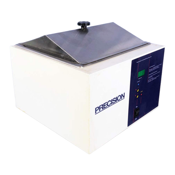
Installation and Operation Manual
280 (2825/2826), 281 (2829/2830), 282 (2833/2834),
283 (2837/2838), 284 (2841/2842), 285 (2845/2846),
401 Millcreek Road, Box 649
Marietta, Ohio 45750
USA
Phone: 740-373-4763
Toll Free: 800-848-3080
FAX: 740-373-4189
Manual P/N 3177877
Rev I Dated 29OCT09
Microprocessor-Controlled
General Purpose Water Baths
286 (2849/2850) and 288 (2853/2854)
Models
Heater On
Calibrate
ENTER
On
Off
To Set Temperature:
5 6
Press
or
until desired temperature is displayed.
Press ENTER - New Set Point is accepted.
Display will then return to actual temperature.
Should Calibration Be Required:
Place certified / traceable thermometer into holder.
Allow to stabilize.
Press Calibrate button.
5 6
Press
or
to match readout to thermometer.
Press ENTER - calibration is complete.
Advertisement
Table of Contents

Related Manuals for Thermo Scientific Precision 280


Summary of Contents for Thermo Scientific Precision 280
- Page 1 Installation and Operation Manual Microprocessor-Controlled General Purpose Water Baths Models 280 (2825/2826), 281 (2829/2830), 282 (2833/2834), 283 (2837/2838), 284 (2841/2842), 285 (2845/2846), 286 (2849/2850) and 288 (2853/2854) To Set Temperature: Press until desired temperature is displayed. Press ENTER - New Set Point is accepted. Display will then return to actual temperature.
- Page 2 NOTICE THE MATERIAL IN THIS MANUAL IS FOR INFORMATION PURPOSES ONLY. THE CONTENTS AND THE PRODUCT IT DESCRIBES ARE SUBJECT TO CHANGE WITHOUT NOTICE. THERMO SCIENTIFIC MAKES NO REPRESENTATIONS OR WARRANTIES WITH RESPECT TO THIS MANUAL. IN NO EVENT SHALL THERMO BE LIABLE FOR ANY DAMAGES, DIRECT OR INCIDENTAL, ARISING OUT OF OR RELATED TO THE USE OF THIS MANUAL.
- Page 3 REVISION STATUS INDEX DATE AMENDED PAGES NOTES Initial release 12/98 02/00 Pictorial update of wiring per ECO JGC000223A 07/01 2,8,9,12,17 updated electrical secifications Add caution "acidic & caustic substance" NOV01 36100112 (340016400) new manual #, manufacture location 4/05 ECR 23443 & 23496 consolidated with the 240V manual 5/06 3177693, updated specs...
-
Page 4: Table Of Contents
Contents 1. Introduction ........................1 2. Unpacking and Damage ....................1 3. General Information ......................2 4. Performance Data ......................3 5. Installation ........................3 6. Explanation of Controls ....................4 7. Operation ......................... 5 8. Maintenance ........................6 9. Troubleshooting ......................7 10. -
Page 6: Introduction
1. 0 INTRODUCTION 2.0 UNPACKING AND DAMAGE 1.01 Your satisfaction and safety are important to 2.01 This product was carefully packed and Thermo and a complete understanding of this thoroughly inspected before leaving our unit is necessary to attain these objectives. factory. -
Page 7: General Information
3.0 GENERAL INFORMATION 3.04 A high limit temperature cutout is provided in the event of an empty water bath. If the sensor reads a temperature 5°C higher than the set 3.01 Precision Baths are widely used in research temperature, a high temperature cutout will and quality control. -
Page 8: Performance Data
PERFORMANCE DATA 5.02 Electrical Connections - WARNING 4.01 The following performance specifications FOR PERSONAL SAFETY, THIS APPARATUS MUST for bath models 280 through 288 are valid only BE PROPERLY GROUNDED. when the gable cover is in place. The power cord provided on this unit is Control sensitivity @ 37C = ±0.1C equipped with a three-prong (grounding) plug Temperature uniformity @ 37C = ±0.2C... -
Page 9: Explanation Of Controls
Heater On Lamp - The "HEATER ON" lamp EXPLANATION OF is lit when power is applied to the heater. CONTROLS Calibrate Key - This key puts the unit in 6.01 Power Switch - The power switch is located calibrate mode to match a traceable near the lower portion of the control panel thermometer to the actual temperature and provides power to the entire unit. -
Page 10: Operation
OPERATION To change the set temperature, continuously press the /\ or \/ key until the desired set CAUTION: temperature is displayed. When continuously EXERCISE CARE WHEN USING ACIDIC OR pressing either the /\ or \/ keys, the display CAUSTIC SOLUTIONS AS THEY WILL ATTACK changes slowly at first but after 1 degree has THE GALVANIZED STEEL BATH BODY IF SPILLED passed, the display begins to change rapidly. -
Page 11: Maintenance
MAINTENANCE CAUTION NEVER USE THE FOLLOWING CHEMICALS: AQUA REGIA FERRIC CHLORIDE IODINE 8.01 Cleaning and care of stainless steel: Stainless SODIUM AZIDE SULFURIC ACID steel will resist corrosion; however, it is not impervious to it. For maximum life, stainless Should the stainless steel ever become steel must receive a certain amount of care. -
Page 12: Troubleshooting
TROUBLESHOOTING 9.02 The following is a list of the tools and instruments required to perform the procedures outlined in the Troubleshooting WARNING Procedures table. SERVICE SHOULD BE PERFORMED BY A QUALIFIED TECHNICIAN. BEFORE REPLACING Suggested Tools: ELECTRICAL OR MECHANICAL COMPONENTS, UNPLUG THE LINE CORD. - Page 13 Troubleshooting Procedures Problem Procedure 9.03 No Heat (cont.) E. If a 5V DC power supply is not available, leave J5 connected to the control board, turn power on, and repeat step D by placing the voltmeter probes on J5, Pins 2 & 3. Check Heater.
- Page 14 Troubleshooting Procedures Problem Procedure Check TRIAC (High voltage output of control board) A. Make sure power is disconnected from the unit. B. Connect an AC voltmeter across the heater capable of reading 120 or 240 volts, depending on your particular unit. C.
-
Page 15: Parts Replacement
10.01 Before removing any parts for replacement, 10.0 PARTS REPLACEMENT verify part in question by following the instructions listed in the troubleshooting WARNING guide. BEFORE REPLACING ANY PART, BE SURE BATH IS DISCONNECTED FROM POWER SOURCE. SERVICE 10.02 Refer to Parts Replacement Table below for SHOULD BE PERFORMED BY A QUALIFIED appropriate replacement procedures. - Page 16 Parts Replacement (cont.) Disconnect the wires that are attached to the heater. 10.05 Replace Control Board (cont.) Then disconnect the temperature sensor from J5 on the control board. Remove the bath pan from the body by removing each 11/32" nut from each corner of the pan. NOTE: Model 2849/2850 has 6 hex nuts which hold the pan in place.
-
Page 17: Replacement Parts List
11.0 Replacement Parts List 120-Volt Models 2825 2829 2833 2837 2841 2845 2849 2853 3177554 3177576 3177572 3177573 3177577 3177574 3177578 3177573 Diffuser Plate Asm. 3163798 3163797 3163798 3163801 3163799 3163805 3163804 3163801 PCB Asm. 3176801 Heater 3175493 3175493 3175494 3175495 3175496 3175496... -
Page 18: Assembly And Schematic Drawings
12.0 ASSEMBLY & SCHEMATIC DRAWINGS... - Page 21 THE FLAT SIDE OF THE SENSOR MUST COME IN CONTACT WITH THE PAN HEATER INSULATOR HEATER HEATER HARNESS TEMPERATURE PROBE ASSEMBLY POWER PCB ASSEMBLY ON/OFF HARNESS POWER LINE SWITCH CORD 120V UNIT TYPICAL BOTTOM VIEW...
- Page 22 THE FLAT SIDE OF THE SENSOR MUST COME IN CONTACT WITH THE PAN HEATER INSULATOR HEATER HEATER HARNESS POWER LINE CORD TEMPERATURE PROBE ASSEMBLY POWER PCB ASSEMBLY ON/OFF HARNESS SWITCH 240V UNIT TYPICAL BOTTOM VIEW...
- Page 23 HEATER HEATER HARNESS ASSEMBLY POWER HARNESS DETAIL "A" TEMPERATURE SENSOR POWER LINE CORD POWER SWITCH 120 VAC WIRING DIAGRAM NOTE: JP3 & JP4 MUST BE INSTALLED FOR 120 VAC OPERATION.
- Page 24 HEATER HEATER HARNESS ASSEMBLY POWER HARNESS DETAIL "A" TEMPERATURE SENSOR POWER POWER SWITCH RECEPTACLE WITH FUSES POWER LINE CORD 240 VAC WIRING DIAGRAM NOTE: JP3 & JP4 MUST BE REMOVED FOR 240VAC OPERATION...
-
Page 26: Warranty
THERMO FISHER SCIENTIFIC INTERNATIONAL DEALER WARRANTY The Warranty Period starts two months from the date your equipment is shipped from our facility. This allows for shipping time so the warranty will go into effect at approximately the same time your equipment is delivered. The warranty protec- tion extends to any subsequent owner during the first year warranty period.
Need help?
Do you have a question about the Precision 280 and is the answer not in the manual?
Questions and answers