Advertisement
Quick Links
SSV WORKS, 201 N. Rice Ave Unit A, Oxnard, CA 93030
www.SSVworks.com
|
Phone: 818-991-1778
RED
RZR3
FOLLOW THE COLOR CODE ON EACH STEP FOR YOUR VEHICLE'S SPECIFIC INSTRUCTIONS
5
pg
Panels, Dash Disassembly,
and Wiring
9
pg
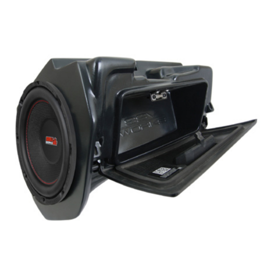
Glovebox Subwoofer
Installation
12
pg
Amp Tray
Installation
15
pg
Kick Panel Speakers
Installation
|
Fax: 866-293-6751
2014-2018
RZ34-Q3ARC
RZR 3 and RZR 4 with Ride Command
SSV Works 3 Speaker Audio Kit
BLUE
RZR4
2019+
Phase 3
Advertisement

Related Manuals for SSV Works RZ34-Q3ARC


Summary of Contents for SSV Works RZ34-Q3ARC
- Page 1 RZ34-Q3ARC RZR 3 and RZR 4 with Ride Command SSV Works 3 Speaker Audio Kit SSV WORKS, 201 N. Rice Ave Unit A, Oxnard, CA 93030 Phase 3 www.SSVworks.com Phone: 818-991-1778 Fax: 866-293-6751 BLUE RZR3 RZR4 2014-2018 2019+ FOLLOW THE COLOR CODE ON EACH STEP FOR YOUR VEHICLE’S SPECIFIC INSTRUCTIONS...
-
Page 2: Parts List
All SSV Works enclosures are covered by a limited lifetime warranty against defects in instructions completely before material or workmanship. All SSV Works Electronics are covered by a limited 1 year warranty installation to avoid possible injury, against defects in material or workmanship. All Kicker Speakers are covered by a limited 1 or damage to the accessory or vehicle. - Page 3 All SSV Works Electronics are covered by a limited 1 year warranty against installation to avoid possible injury, defects in material or workmanship. All SSV Works Speakers are covered by a limited 1 year or damage to the accessory or vehicle.
- Page 4 All SSV Works enclosures are covered by a limited lifetime warranty against defects in instructions completely before material or workmanship. All SSV Works Electronics are covered by a limited 1 year warranty installation to avoid possible injury, against defects in material or workmanship. All Kicker Speakers are covered by a limited 1 or damage to the accessory or vehicle.
- Page 5 PANELS AND DASH DISASSEMBLY (ALL MODELS) A. Remove all seats by releasing the handle behind each seat, B. Disconnect the negative battery cable from the battery. push forward slightly while lifting up. C. Remove all of the center console push pins and T-40 Torx screws. For 4-seat models, disconnect the harness attached to the 12v accessory socket. PANELS AND DASH DISASSEMBLY (RZR3) D.
- Page 6 PANELS AND DASH DISASSEMBLY (RZR4) D1. Remove hood by turning locking pins and lifting up. D2. Unscrew the (4) T40 torx screws and extract the (2) push pins from the top-center Ride Command bezel. Lift and remove the top-center Ride Command bezel. From inside the machine, pull the dash towards you to unclip.
- Page 7 RUNNING WIRING AND CABLES (RZR4) A. Extract the (4) T40 surrounding the ride command system OR top-center dash B. Extract the (1) T40 torx that secures the lower dash pocket. compartment (for non-Ride Command vehicles) and (2) push pins found in the Disconnect the USB and unclip the LED from the lower dash pocket.
- Page 8 These following steps are needed to ensure clearance for the sub enclosure and allow proper performance for vehicles with Polaris Dynamix. B. Tilt the brain back, unsnap the perimeter of the connector cover as it will be A. Start by removing the four (4) 10mm bolts securing the Dynamix replaced by the provided cover that has a cable relief cut-out.
- Page 9 GLOVE BOX SUBWOOFER ENCLOSURE (ALL MODELS) A. Using (4) 8mm screws and washers, attach Bracket “B” to the B. Install door latch onto enclosure with the provided (2) T30 enclosure. M6x8mm screws. C. Install left and right door hinge brackets using (2) 8mm screws and washers D.
- Page 10 F. Lift the enclosure into place. Using the factory glove box mounting hardware, fasten the enclosure into place. Pull sub enclosure wiring towards the center of the vehicle to avoid being pinched by the chassis. G. Place Bracket “A” into place towards the firewall, and fasten H.
- Page 11 STOP The next steps will either be for RZR’s with OR without factory Ride Command door speakers. If you do not have factory Ride If you do have factory Ride Command door speakers, Command door speakers, proceed to page 14. proceed to page 13.
- Page 12 Follow these steps if you currently have the Polaris factory door speakers already installed. This process will deactivate the factory amp and speakers. If you want to continue to use the factory system with this audio system, please contact SSV Works at 818-991-1778 x2 or email support@SSVworks.com Disconnect and uninstall the factory amplifier.
- Page 13 AMP TRAY INSTALLATION (RZR3) Place the pre-assembled amp plate on the frame of the dash and line up the hole on the top of the amp plate to the factory hole where the pocket bracket was previously installed (1). Loosely screw in the factory 10mm screw in this hole location that was previously removed.
- Page 14 AMP TRAY INSTALLATION - WITHOUT FACTORY AUDIO (RZR4) A. Place the amp tray base bracket at the location of the (2) removed B. Place the amp tray into the mounting location by lining up the amp factory 10mm bolts. Re-fasten the bolts through both the amp tray plate screw holes to the factory holes on the chassis and base base bracket and factory plate to secure to the chassis.
- Page 15 FRONT KICK PANELS (ALL MODELS) DRIVER PASSENGER Route the B-H1909 across the dash cavity. The cable marked as “DRIVER” will route under the dash and down to the driver side footwell, the cable marked “PASSENGER” will route over the top and down the right side of the RZ4-GB10 enclosure. A.
- Page 16 F. Connect the B-H1909 speaker harness to the 300.4 amplifier E. Connect the B-H1909 cable to the speaker pod and zip tie all front output. cables to the frame. G. Repeat Steps A-E to install passenger kick pod. CONNECTING POWER & GROUND CABLE TO BATTERY (ALL MODELS) Battery Terminal Cable...
- Page 17 E. Zip tie all of the electrical cabling (factory and audio) along the center 40A fuse, screw the 2 screws back in and reattach the fuse holder top. column away from the drive shaft. THIS CONCLUDES THE INSTALLATION PROCESS. © 2022 SSV Works, Oxnard, CA 93030 RZ34-Q3ARC 7-26-22...
Need help?
Do you have a question about the RZ34-Q3ARC and is the answer not in the manual?
Questions and answers