Table of Contents
Advertisement
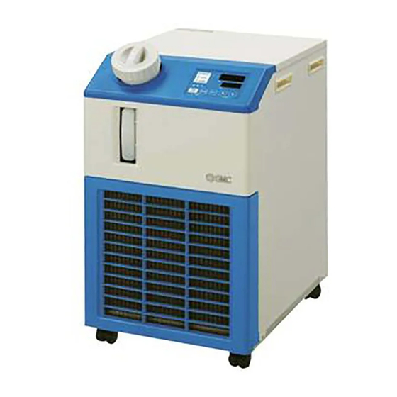
Service Manual
Air-cooled
refrigerated type
HRS012-A
-10-
HRS018-A
-10-
HRS012-A
-20-
HRS018-A
-20-
HRS024-A
-20-
HRS030-A
-20-
Keep this manual available whenever necessary.
Thermo-chiller
st
1
Water-cooled
refrigerated type
HRS012-W
-10-
HRS018-W
-10-
HRS012-W
-20-
HRS018-W
-20-
HRS024-W
-20-
HRS030-W
-20-
© 2015 SMC CORPORATION All Rights Reserved
HRX-MM-N007
edition: Feb. 2010
Rev.P: Nov. 2015
Advertisement
Table of Contents
Troubleshooting

Related Manuals for SMC Networks HRS012-A-10 Series


Summary of Contents for SMC Networks HRS012-A-10 Series
- Page 1 HRX-MM-N007 edition: Feb. 2010 Rev.P: Nov. 2015 Service Manual Thermo-chiller Air-cooled Water-cooled refrigerated type refrigerated type HRS012-A -10- HRS012-W -10- HRS018-A -10- HRS018-W -10- HRS012-A -20- HRS012-W -20- ...
- Page 2 To users Thank you for purchasing our Thermo-chiller HRS Series (hereinafter called “This system”). For safe use of this system and personal safety, be sure to read and understand this manual thoroughly before performing repair of this system. Warnings and precautions defined in this manual shall be observed. ...
-
Page 3: Table Of Contents
HRX-MM-N007 Contents Contents Chapter 1 Safety Instructions ............1-1 Before Using Unit ....................1-1 Reading the Manual ....................1-1 Hazards ........................1-2 1.3.1 Level of hazards ........................1-2 Definition of “Serious injury” and “Light injury” ..............1-2 1.3.2 1.3.3 Types of hazard labels ......................1-3 1.3.4 Locations of hazard labels .................... - Page 4 HRX-MM-N007 Contents AL09: Circulating fluid discharge pressure drop ................3-45 AL10: High compressor intake temp.................... 3-46 AL11: Low compressor intake temp..................... 3-48 AL12: Low super heat temperature ....................3-51 AL13: High compressor discharge pressure [For air-cooled type] ..........3-56 AL13: High compressor discharge pressure [For water-cooled type] ..........
- Page 5 HRX-MM-N007 Contents Precautions for Whole Work ................... 4-1 4.1.1 Preparation for work ......................4-1 4.1.2 Check after work ........................4-1 Work Procedure ....................... 4-2 4.2.1 Removal and the mounting of the panel ................4-2 4.2.2 Discharge of the circulating fluid and facility water .............. 4-4 Check After Work ....................
- Page 6 HRX-MM-N007 Contents 5.3.2 Panel............................. 5-4 5.3.3 Temperature sensor ......................5-5 5.3.4 Hose ............................. 5-5 5.3.5 Pressure sensor (For circulating fluid) .................. 5-6 5.3.6 Level switch .......................... 5-6 5.3.7 DC power supply ........................5-7 5.3.8 Main board / Communication board / Power board / Display board / Fuse ......5-8 5.3.9 Power switch ........................
-
Page 7: Chapter 1 Safety Instructions
HRX-MM-N007 Chapter 1 Safety Instructions Chapter 1 Safety Instructions Read most critical instruction to be considered carefully and ensure well understanding of the content before operating the unit 1.1 Before Using Unit This chapter is intended to specifically describe the safety related issues for handling the unit. -
Page 8: Hazards
HRX-MM-N007 Chapter 1 Safety Instructions 1.3 Hazards 1.3.1 Level of hazards The instructions given in this manual aim to assure safe and correct operation of the unit and to prevent injury of operators or damage to the unit. These instructions are grouped into three categories, Danger, Warning and Caution, which indicate the level of hazard, damage and also the degree of emergency. -
Page 9: Types Of Hazard Labels
HRX-MM-N007 Chapter 1 Safety Instructions 1.3.3 Types of hazard labels The unit has various potential hazards and they are marked with warning labels. Be sure the read this section before starting any work on the unit. Warning related to electricity This symbol stands for a possible risk of electric shock. -
Page 10: Locations Of Hazard Labels
HRX-MM-N007 Chapter 1 Safety Instructions 1.3.4 Locations of hazard labels There are various warning labels on the product to show the potential hazards. Rear Fig.1.3-1 Warning label position Front For air-cooled type Fig.1.3-2 Warning label position 1.3 Hazards HRS Series... -
Page 11: Other Labels
HRX-MM-N007 Chapter 1 Safety Instructions Other Labels 1.4.1 Product label Information about the product, such as Serial No. and Model No. can be found on the model label. This information is needed when contacting an SMC sales distributor. Front Model Number Serial Number (SERIAL No.) The type and quantity of... -
Page 12: Waste Disposal
HRX-MM-N007 Chapter 1 Safety Instructions Check all parts and screws are fitted correctly and securely after maintenance. Avoid working in a drunken or sick condition, which might cause an accident. Do not remove the panels except for the cases permitted in this manual. ... -
Page 13: Chapter 2 Name Of Parts
HRX-MM-N007 Chapter 2 Name of Parts Chapter 2 Name of Parts 2.1 Appearance Fig.2.1-1 Name of Parts (HRS012/018/024---) HRS Series 2.1 Appearance... - Page 14 HRX-MM-N007 Chapter 2 Name of Parts Optuon B 【Earth leakage breaker】 Lid for circulating fluid fill port Option J 【Automatic water-fill specifications】 Operation display panel Automatic water-fill port Rc3/8 Overflow port Rc3/4 (21)[mm (500)[mm (377)[mm (0.8)[in] (19.7)[in] (14.8)[in] Circulating fluid return port Rc1/2 Power switch Circulating fluid...
-
Page 15: Component Parts
HRX-MM-N007 Chapter 2 Name of Parts 2.2 Component Parts Tank Tank lid Valve for automatic water-fill For option J [With automatic water-fill] Level switch Power supply switch Inlet socket (For air-cooled type) Fig.2.2-1 Component Parts Main board Display board Temperature sensor DC24V power supply Power board Communication board... - Page 16 HRX-MM-N007 Chapter 2 Name of Parts 2.2 Component Parts HRS Series...
-
Page 17: Chapter 3 Alarm Indication And Troubleshooting
HRX-MM-N007 Chapter 3 Alarm Indication and Troubleshooting Chapter 3 Alarm Indication and Troubleshooting 3.1 Alarm Display When any alarm occurs, the product responds with the following conditions. The [ALARM] lamp will flash. The alarm buzzer sounds. The alarm no. is displayed on PV. ... -
Page 18: Error Type And Alarm Set Value
HRX-MM-N007 Chapter 3 Alarm Indication and Troubleshooting 3.2 Error Type and Alarm Set Value Table 3-1 Error Type and Alarm Set Value (1/2) Cause / Remedy Code Descriptioin Operation (Press the reset key after eliminating the cause.) The fluid level has fallen below the level indicator. Fill the ... - Page 19 HRX-MM-N007 Chapter 3 Alarm Indication and Troubleshooting Table 3-2 Error Type and Alarm Set Value (2/2) Cause / Remedy Code Descriptioin Operation (Press the reset key after eliminating the cause.) Continued AL28 Maintenance of pump The timing of a periodical check is informed. ...
-
Page 20: How To Reset Alarm
HRX-MM-N007 Chapter 3 Alarm Indication and Troubleshooting 3.2.1 How to reset alarm The troubleshooting method depends which alarm has been generated. Refer to’’ Table 3-1 ’’. This page explains how to reset the alarm signal condition after eliminating the cause of the alarm. Ensure that the alarm display screen is displayed. -
Page 21: Troubleshooting
HRX-MM-N007 Chapter 3 Alarm Indication and Troubleshooting 3.3 Troubleshooting 3.3.1 How to use the flow chart of troubleshooting Find a flow chart of troubleshooting corresponding to the error, referring to table 3-1 “Error Type and Alarm Set Value”. Troubleshoot a problem through an item-by-item check in the flow chart. [Tips] Go through the items of guidelines from top down for troubleshooting. -
Page 22: Icons For Necessary Tools And Specifications
HRX-MM-N007 Chapter 3 Alarm Indication and Troubleshooting 3.3.2 Icons for necessary tools and specifications ■ Tools necessary for troubleshooting Table 3-3 Tools necessary for troubleshooting Description Icon Content Cross recessed - 1 screwdriver Flat blade - 1 screwdriver Spanner/Wrench Flat size: 14mm For current/ frequency... -
Page 23: Removal And The Mounting Of The Panel
HRX-MM-N007 Chapter 3 Alarm Indication and Troubleshooting 3.3.3 Removal and the mounting of the panel Be sure to wear protective footwear and gloves when attaching or removing panels. Sharp edges of the panels may lead to personal injury if not handled properly. - Page 24 HRX-MM-N007 Chapter 3 Alarm Indication and Troubleshooting Right side panel Fig. 3.3-2 Removal of panels ■ Mounting Panel attachment is performed in inverse order of its removal. 3.3 Troubleshooting HRS Series...
-
Page 25: Troubleshooting Of Alarms
HRX-MM-N007 Chapter 3 Alarm Indication and Troubleshooting 3.3.4 Troubleshooting of alarms AL01: Low level in tank <Detection method> The level switch in the tank operates to detect the alarm. AL01 Low level in tank Add circulating Is the circulating fluid at Is there circulating fluid Is there circulating fluid fluid. - Page 26 HRX-MM-N007 Chapter 3 Alarm Indication and Troubleshooting Check the connection Securely connect the connectors to [CN9] of the main board. Pins of [LS1] must be securely inserted to the connectors. There must not be any incorrect insertion of the pins and defective crimping. Fig.
-
Page 27: Al02: High Circulating Fluid Discharge Temp. [For Air-Cooled Type]
HRX-MM-N007 Chapter 3 Alarm Indication and Troubleshooting AL02: High circulating fluid discharge temp. [For air-cooled type] <Detection method> This alarm goes off when the temperature sensor for the circulating fluid (for discharge) detects 60 C or more. High circulating fluid discharge temp. AL02 [For air-cooled type] AL22: Circulating fluid... - Page 28 HRX-MM-N007 Chapter 3 Alarm Indication and Troubleshooting To the previous page Normal Check the pressure Go back to "11. Check if the sensor in the refrigerant coolant leaks". circuit. Error Error Check for an input from the pressure sensor in the refrigerant circuit.
- Page 29 HRX-MM-N007 Chapter 3 Alarm Indication and Troubleshooting Ambient temperature is out of the specification range. Ambient temperature is higher than 40 C (45 C for Option G "High ambient temperature specification"). External load is out of the specification range. Cooling capacity varies depending on the ambient temperature, set circulating fluid temperature, and power supply frequency.
- Page 30 HRX-MM-N007 Chapter 3 Alarm Indication and Troubleshooting Check the circulating fluid temperature sensor (PT1) after it is replaced. Replace the circulating fluid temperature sensor (PT1). (See section "4.5.1 Replacement of temperature sensor (PT1)".) After replacing, check that all the check items shown in "5. Check the circulating fluid temperature sensor (PT1)"...
- Page 31 HRX-MM-N007 Chapter 3 Alarm Indication and Troubleshooting 11. Check for refrigerant leakage. Refrigerant leakage reduces the cooling capacity. To check for refrigerant leakage, it is necessary to make the refrigerant circuit temperature same as the ambient temperature. Stop the Thermo-Chiller operation, and leave it not operating for 24 hours.
- Page 32 HRX-MM-N007 Chapter 3 Alarm Indication and Troubleshooting 13. Check for an input to the pressure sensor in the refrigerant circuit. Check that the power is supplied to the refrigerant circuit pressure sensor. Check voltage by contacting the probe of the tester directly to the connector external surface with the "CN4"...
- Page 33 HRX-MM-N007 Chapter 3 Alarm Indication and Troubleshooting 14. Check the display of the refrigerant circuit pressure sensor (for high pressure). Compare the refrigerant circuit pressure and the ambient temperature with those shown in the graph to check the displayed value of the refrigerant circuit pressure sensor. Follow the instructions shown below: Leave the Thermo-Chiller not operating for 24 hours to make the ambient temperature and the temperature inside the Thermo-Chiller the same.
- Page 34 HRX-MM-N007 Chapter 3 Alarm Indication and Troubleshooting 16. Check the analogue output of the refrigerant circuit pressure sensor (for high pressure). Find out if the main board is operating connectly. Follow the instructions shown below: (1) Check the "Ph: Refrigerant circuit pressure on the high pressure side" value in the "Check Monitor Menu".
- Page 35 HRX-MM-N007 Chapter 3 Alarm Indication and Troubleshooting 17. Check the analogue output of the refrigerant circuit pressure sensor (for low pressure). Find out if the main board is operating connectly. Follow the instructions shown below: (1) Check the "PL: Refrigerant circuit pressure on the low pressure side" value in the "Check Monitor Menu".
-
Page 36: Al02: High Circulating Fluid Discharge Temp. [For Water-Cooled Type]
HRX-MM-N007 Chapter 3 Alarm Indication and Troubleshooting AL02: High circulating fluid discharge temp. [For water-cooled type] <Detection method> This alarm goes off when the temperature sensor for the circulating fluid (for discharge) detects 60 C or more. High circulating fluid discharge temp. AL02 [For water-cooled type] AL22: Circulating fluid... - Page 37 HRX-MM-N007 Chapter 3 Alarm Indication and Troubleshooting With Repair the refrigerant circuit. Normal leakage Check the pressure Only a specialized operator is sensor in the refrigerant Check if the coolant leaks. allowed to handle the refrigerant circuit. circuit. Error No leakage Electronic expansion valve, which is a part of the refrigerant circuit, needs to be replaced.
- Page 38 HRX-MM-N007 Chapter 3 Alarm Indication and Troubleshooting Check the facility water system. Check that the facility water system capability satisfies the required facility water flow rate that is specified in the Operation Manual. Facility water is contaminated. Check that the facility water is clean (without any foreign matter or discolouration). Incorrect flow rate of the facility water.
- Page 39 HRX-MM-N007 Chapter 3 Alarm Indication and Troubleshooting Check the circulating fluid temperature sensor (PT1). Two circulating fluid temperature sensors are used; one is for the outlet port (PT1) and one for the return port (PT2). Compare the temperatures sensed by the temperature sensors under the conditions shown below to judge if the values provided by the temperature sensors are correct or not: (1) Connect a shorter pipe directly from the circulating fluid outlet port to the return port of the...
- Page 40 HRX-MM-N007 Chapter 3 Alarm Indication and Troubleshooting <With contamination with the heat exchanger> "t3: Suction temperature of the compressor" ˂ "t2: Circulating fluid return temperature" -5 e.g. (Normal) t2: 21.5, t3: 23.8, (Abnormal) t2: 21.5, t3: 15.5 11. Check the pressure sensor in the refrigerant circuit. Two pressure sensors, one for high pressure and the other for low pressure, are used for the refrigerant circuit.
- Page 41 HRX-MM-N007 Chapter 3 Alarm Indication and Troubleshooting 14. Check for an input to the pressure sensor in the refrigerant circuit. Check that the power is supplied to the refrigerant circuit pressure sensor. Check voltage by contacting the probe of the tester directly to the connector external surface with the "CN4"...
- Page 42 HRX-MM-N007 Chapter 3 Alarm Indication and Troubleshooting 15. Check the display of the refrigerant circuit pressure sensor (for high pressure). Compare the refrigerant circuit pressure and the ambient temperature with those shown in the graph to check the displayed value of the refrigerant circuit pressure sensor. Follow the instructions shown below: (1) Leave the Thermo-Chiller not operating for 24 hours to make the ambient temperature and the temperature inside the Thermo-Chiller the same.
- Page 43 HRX-MM-N007 Chapter 3 Alarm Indication and Troubleshooting 17. Check the analogue output of the refrigerant circuit pressure sensor (for high pressure). Find out if the main board is operating connectly. Follow the instructions shown below: (1) Check the "Ph: Refrigerant circuit pressure on the high pressure side" value in the "Check Monitor Menu".
- Page 44 HRX-MM-N007 Chapter 3 Alarm Indication and Troubleshooting 18. Check the analogue output of the refrigerant circuit pressure sensor (for low pressure). Find out if the main board is operating connectly. Follow the instructions shown below: (1) Check the "PL: Refrigerant circuit pressure on the low pressure side" value in the "Check Monitor Menu".
-
Page 45: Al03: Circulating Fluid Discharge Temp. Rise
HRX-MM-N007 Chapter 3 Alarm Indication and Troubleshooting AL03: Circulating fluid discharge temp. rise <Detection method> This alarm goes off when the temperature sensor for the circulating fluid (for discharge) detects 45 C or more (can be changed). Circulating fluid discharge AL03 temp. -
Page 46: Al04: Circulating Fluid Discharge Temp. Drop
HRX-MM-N007 Chapter 3 Alarm Indication and Troubleshooting AL04: Circulating fluid discharge temp. drop <Detection method> This alarm goes off when the temperature sensor for the circulating fluid (for discharge) detects 1 C or less (can be changed). Circulating fluid discharge AL04 temp. - Page 47 HRX-MM-N007 Chapter 3 Alarm Indication and Troubleshooting Cooling load that is larger than the heating capacity is being applied to the Thermo-Chiller. Please refer to the "Heating capacity" graph shown in the Operation Manual. Check the circulating fluid temperature sensor (PT1). Two circulating fluid temperature sensors are used;...
-
Page 48: Al05: High Circulating Fluid Return Temp
HRX-MM-N007 Chapter 3 Alarm Indication and Troubleshooting AL05: High circulating fluid return temp. <Detection method> This alarm goes off when the temperature sensor for the circulating fluid (for fluid return) detects 60 C or more. High circulating fluid return AL05 temp. - Page 49 HRX-MM-N007 Chapter 3 Alarm Indication and Troubleshooting External load is out of the specification range. Cooling capacity varies depending on the ambient temperature, facility water temperature, set circulating fluid temperature, and power supply frequency. Please refer to the "Cooling capacity" graph shown in the Operation Manual. The alarm goes off right after the Thermo-Chiller starts.
-
Page 50: Al06: High Circulating Fluid Discharge Pressure
HRX-MM-N007 Chapter 3 Alarm Indication and Troubleshooting AL06: High circulating fluid discharge pressure <Detection method> This alarm goes off when the pressures detected by the circulating fluid pressure sensor (for discharge) reach the following values. - Standard pump: The alarm will not be generated. - Option T (High pressure pump): 0.70 MPa - Option MT (High pressure pump for pure water): 0.60 MPa High circulating fluid discharge... - Page 51 HRX-MM-N007 Chapter 3 Alarm Indication and Troubleshooting Check the external piping. Check if the external piping is in the conditions shown below: (1) The external piping has close bending, curves at a sharp angle or clogging. (2) A valve or a switching valve is mounted in the middle of the external piping, and it closes the piping temporarily.
- Page 52 HRX-MM-N007 Chapter 3 Alarm Indication and Troubleshooting AL25 goes off when the circulating fluid pressure sensor connector is disconnected. Confirm that "AL25: Circulating fluid discharge pressure sensor failure" goes off when the connector "PS1" of the circulating fluid pressure sensor (for discharge) is pulled out.
-
Page 53: Al07: Abnormal Pump Operation
HRX-MM-N007 Chapter 3 Alarm Indication and Troubleshooting AL07: Abnormal pump operation <Detection method> This alarm goes off when the pressures detected by the circulating fluid pressure sensor (for discharge) is 0.05 MPa or less. AL07 Pump operation failure Refer to the section "AL25: Circulating fluid Is AL25 being generated? discharge pressure... - Page 54 HRX-MM-N007 Chapter 3 Alarm Indication and Troubleshooting Check the power supply voltage. Check that the power supply voltage is within the specified range. Check the power supply voltage that is supplied to the connector of the power supply cable to be connected to Thermo-Chiller with a tester.
- Page 55 HRX-MM-N007 Chapter 3 Alarm Indication and Troubleshooting Check the pump performance. Operate the Thermo-Chiller as a single unit. Install a pressure gauge (measurable range: approx. 0 to 1 MPa), a valve (with approximate flow adjustability), and a flow meter (measurable range: approx. 0 to 30 L/min) to the Thermo-Chiller. Make an isolated operation of the pump (by pressing the "RUN/STOP"...
- Page 56 HRX-MM-N007 Chapter 3 Alarm Indication and Troubleshooting Check the main board. Check that the main board outputs signals. Disconnect the connector "CN1" on the power board. Perform settings of the tester to make it possible to measure 24 VDC. Contact the negative side probe to the connector pin number 6 on the cable side of the "CN1" that has been removed, and contact the positive side probe to the pin number 8.
- Page 57 HRX-MM-N007 Chapter 3 Alarm Indication and Troubleshooting Check the power board. Check that the power is being supplied to the pump. Disconnect the connector "CN3" of the power board to which the pump cable is connected. Check if power supply voltage is being supplied to the "CN3" connector (Pin No. 1 and No.2) of the power board with a tester while the pump makes an isolated operation (by pressing "RUN/STOP"...
-
Page 58: Al08: Circulating Fluid Discharge Pressure Rise
HRX-MM-N007 Chapter 3 Alarm Indication and Troubleshooting AL08: Circulating fluid discharge pressure rise <Detection method> This alarm goes off when the pressures detected by the circulating fluid pressure sensor (for discharge) reach the following values (change in the values acceptable). - Standard pump: 0.30 MPa - Option T (High pressure pump): 0.70 MPa - Option MT (High pressure pump for pure water): 0.60 MPa... - Page 59 HRX-MM-N007 Chapter 3 Alarm Indication and Troubleshooting Check the external piping. Check if the external piping is in the conditions shown below: (1) The external piping has close bending, curves at a sharp angle or clogging. (2) A valve or a switching valve is mounted in the middle of the external piping, and it closes the piping temporarily.
- Page 60 HRX-MM-N007 Chapter 3 Alarm Indication and Troubleshooting AL25 goes off when the circulating fluid pressure sensor connector is disconnected. Confirm that "AL25: Circulating fluid discharge pressure sensor failure" goes off when the connector "PS1" of the circulating fluid pressure sensor (for discharge) is pulled out.
-
Page 61: Al09: Circulating Fluid Discharge Pressure Drop
HRX-MM-N007 Chapter 3 Alarm Indication and Troubleshooting AL09: Circulating fluid discharge pressure drop <Detection method> This alarm goes off when the pressures detected by the circulating fluid pressure sensor (for discharge) is 0.05 MPa or less (change in the values acceptable). Circulating fluid discharge AL09 pressure drop... -
Page 62: Al10: High Compressor Intake Temp
HRX-MM-N007 Chapter 3 Alarm Indication and Troubleshooting AL10: High compressor intake temp. <Detection method> This alarm goes off when the compressor intake temperature sensor detects 60 or more. High compressor intake AL10 temp. Refer to section "AL24: Compressor intake temp. Is AL24 being generated? sensor failure". - Page 63 HRX-MM-N007 Chapter 3 Alarm Indication and Troubleshooting External load is out of the specification range. Cooling capacity varies depending on the ambient temperature, facility water temperature, set circulating fluid temperature, and power supply frequency. Please refer to the "Cooling capacity" graph shown in the Operation Manual. Check the external piping.
-
Page 64: Al11: Low Compressor Intake Temp
HRX-MM-N007 Chapter 3 Alarm Indication and Troubleshooting AL11: Low compressor intake temp. <Detection method> This alarm goes off when the compressor intake temperature sensor detects -15 or less. Low compressor intake AL11 temp. Refer to section "AL04: Is AL24 being generated? IS AL04 being generated? Circulating fluid discharge temp. - Page 65 HRX-MM-N007 Chapter 3 Alarm Indication and Troubleshooting Cooling load that is larger than the heating capacity is being applied to the Thermo-Chiller. Please refer to the "Heating capacity" graph shown in the Operation Manual. Flow rate of the circulating fluid is less than 5 L/min. Install a flow meter, and check the flow rate of the circulating fluid.
- Page 66 HRX-MM-N007 Chapter 3 Alarm Indication and Troubleshooting "t3: Suction temperature of the compressor" ˂ "t2: Circulating fluid return temperature" -5 e.g. (Normal) t2: 21.5, t3: 23.8, (Abnormal) t2: 21.5, t3: 15.5 After stopping power supply, check for the same alarm goes off again when the chiller is re-started.
-
Page 67: Al12: Low Super Heat Temperature
HRX-MM-N007 Chapter 3 Alarm Indication and Troubleshooting AL12: Low super heat temperature <Detection method> This alarm goes off when the compressor intake temperature sensor detects the value that is lower than the converted temperature by the refrigerant circuit pressure sensor (for low pressure). AL12 Low super heat temp. - Page 68 HRX-MM-N007 Chapter 3 Alarm Indication and Troubleshooting Flow rate of the circulating fluid is less than 5 L/min. Install a flow meter, and check the flow rate of the circulating fluid. Check the pump performance. Install a flow meter. Refer to the "Pump capacity" graph" shown in the catalogue and check that the pump capacity is suitable for the circulating fluid outlet pressure and the circulating fluid flow rate.
- Page 69 HRX-MM-N007 Chapter 3 Alarm Indication and Troubleshooting Check the pressure sensor in the refrigerant circuit. Two pressure sensors, one for high pressure and the other for low pressure, are used for the refrigerant circuit. Take the following instructions to check for any abnormality with the pressure sensors: (1) Stop the Thermo-Chiller operation.
- Page 70 HRX-MM-N007 Chapter 3 Alarm Indication and Troubleshooting Check the display of the refrigerant circuit pressure sensor (for low pressure). Compare the refrigerant circuit pressure and the ambient temperature with those shown in the graph to check the displayed value of the refrigerant circuit pressure sensor. Follow the instructions shown below: (1) Leave the Thermo-Chiller not operating for 24 hours to make the ambient temperature and the temperature inside the Thermo-Chiller the same.
- Page 71 HRX-MM-N007 Chapter 3 Alarm Indication and Troubleshooting 10. Check the analogue output of the refrigerant circuit pressure sensor (for low pressure). Find out if the main board is operating connectly. Follow the instructions shown below: (1) Check the "PL: Refrigerant circuit pressure on the low pressure side" value in the "Check Monitor Menu".
-
Page 72: Al13: High Compressor Discharge Pressure [For Air-Cooled Type]
HRX-MM-N007 Chapter 3 Alarm Indication and Troubleshooting AL13: High compressor discharge pressure [For air-cooled type] <Detection method> This alarm goes off when the pressure detected by the refrigerant circuit pressure sensor (for high pressure) is 2.6 MPa (Option G: 2.8 MPa) or more. High compressor discharge pressure AL13 [For air-cooled type]... - Page 73 HRX-MM-N007 Chapter 3 Alarm Indication and Troubleshooting To the previous page Normal Go to step "11. After stopping the Check the pressure sensor power supply, the same alarm in the refrigerant circuit. goes off again when the chiller is restarted." Error Error Check for an input to...
- Page 74 HRX-MM-N007 Chapter 3 Alarm Indication and Troubleshooting Ambient temperature is out of the specification range. Ambient temperature is higher than 40 C (45 C for Option G "High ambient temperature specification"). External load is out of the specification range. Cooling capacity varies depending on the ambient temperature, set circulating fluid temperature, and power supply frequency.
- Page 75 HRX-MM-N007 Chapter 3 Alarm Indication and Troubleshooting Check the power board. Check that the power is being supplied to the fan motor. Disconnect the connector "CN4" of the power board to which the fan/compressor cable is connected. Operate the Thermo-Chiller (by pressing "RUN/STOP" key), and check if power supply voltage is supplied to the pins number 1 to number 3 of the "CN4"...
- Page 76 HRX-MM-N007 Chapter 3 Alarm Indication and Troubleshooting 10. Check the pressure sensor in the refrigerant circuit. Two pressure sensors, one for the high pressure and one for the low pressure, are used for the refrigerant circuit. The following instructions are to check for any abnormality with the pressure sensors: (1) Stop the Thermo-Chiller operation.
- Page 77 HRX-MM-N007 Chapter 3 Alarm Indication and Troubleshooting 13. Check the display of the refrigerant circuit pressure sensor (for high pressure). Compare the refrigerant circuit pressure and the ambient temperature with those shown in the graph to check the displayed value of the refrigerant circuit pressure sensor. Follow the instructions shown below: (1) Leave the Thermo-Chiller not operating for 24 hours to make the ambient temperature and the temperature inside the Thermo-Chiller the same.
- Page 78 HRX-MM-N007 Chapter 3 Alarm Indication and Troubleshooting 15. Check the analogue output of the refrigerant circuit pressure sensor (for high pressure). Find out if the main board is operating connectly. Follow the instructions shown below: (1) Check the "Ph: Refrigerant circuit pressure on the high pressure side" value in the "Check Monitor Menu".
- Page 79 HRX-MM-N007 Chapter 3 Alarm Indication and Troubleshooting 16. Check the analogue output of the refrigerant circuit pressure sensor (for low pressure). Find out if the main board is operating connectly. Follow the instructions shown below: (1) Check the "PL: Refrigerant circuit pressure on the low pressure side" value in the "Check Monitor Menu".
-
Page 80: Al13: High Compressor Discharge Pressure [For Water-Cooled Type]
HRX-MM-N007 Chapter 3 Alarm Indication and Troubleshooting AL13: High compressor discharge pressure [For water-cooled type] <Detection method> This alarm goes off when the pressure detected by the refrigerant circuit pressure sensor (for high pressure) is 2.6 MPa or more. High compressor discharge pressure AL13 [For water-cooled type] Is the facility water... - Page 81 HRX-MM-N007 Chapter 3 Alarm Indication and Troubleshooting To the previous page Go to step "9. After stopping the Normal Check the pressure power supply, the same alarm sensor in the refrigerant goes off again when the chiller is circuit. restarted." Error Error Check for an input to the...
- Page 82 HRX-MM-N007 Chapter 3 Alarm Indication and Troubleshooting Incorrect flow rate of the facility water. Install a flow meter and check that the facility water system satisfies the required facility water flow rate that is specified in the Operation Manual. * Facility water does not flow when the Thermo-Chiller is not operating. Check the facility water flow rate while the external load is being applied to the Thermo-Chiller or the circulating fluid temperature is being decreased.
- Page 83 HRX-MM-N007 Chapter 3 Alarm Indication and Troubleshooting Check the pressure sensor in the refrigerant circuit. Two pressure sensors, one for high pressure and the other for low pressure, are used for the refrigerant circuit. Take the following instructions to check for any abnormality with the pressure sensors: (1) Stop the Thermo-Chiller operation.
- Page 84 HRX-MM-N007 Chapter 3 Alarm Indication and Troubleshooting 11. Check the display of the refrigerant circuit pressure sensor (for high pressure). Compare the refrigerant circuit pressure and the ambient temperature with those shown in the graph to check the displayed value of the refrigerant circuit pressure sensor. Follow the instructions shown below: (1) Leave the Thermo-Chiller not operating for 24 hours to make the ambient temperature and the temperature inside the Thermo-Chiller the same.
- Page 85 HRX-MM-N007 Chapter 3 Alarm Indication and Troubleshooting 13. Check the analogue output of the refrigerant circuit pressure sensor (for high pressure). Find out if the main board is operating connectly. Follow the instructions shown below: (1) Check the "Ph: Refrigerant circuit pressure on the high pressure side" value in the "Check Monitor Menu".
- Page 86 HRX-MM-N007 Chapter 3 Alarm Indication and Troubleshooting 14. Check the analogue output of the refrigerant circuit pressure sensor (for low pressure). Find out if the main board is operating connectly. Follow the instructions shown below: (1) Check the "PL: Refrigerant circuit pressure on the low pressure side" value in the "Check Monitor Menu".
-
Page 87: Al15: Refrigerant Circuit Pressure (High Pressure Side) Drop
HRX-MM-N007 Chapter 3 Alarm Indication and Troubleshooting AL15: Refrigerant circuit pressure (high pressure side) drop <Detection method> This alarm goes off when the pressure detected by the refrigerant circuit pressure sensor (for high pressure) is 0.1 MPa or less. Refrigerant circuit pressure AL15 (high pressure side) drop Refer to the section "AL26:... - Page 88 HRX-MM-N007 Chapter 3 Alarm Indication and Troubleshooting Check the pressure sensor in the refrigerant circuit. Two pressure sensors, one for high pressure and the other for low pressure, are used for the refrigerant circuit. Take the following instructions to check for any abnormality with the pressure sensors: (1) Stop the Thermo-Chiller operation.
- Page 89 HRX-MM-N007 Chapter 3 Alarm Indication and Troubleshooting Check for an input to the pressure sensor in the refrigerant circuit. Check that the power is supplied to the refrigerant circuit pressure sensor. Check voltage by contacting the probe of the tester directly to the connector external surface with the "CN4"...
- Page 90 HRX-MM-N007 Chapter 3 Alarm Indication and Troubleshooting Check the display of the refrigerant circuit pressure sensor (for high pressure). Compare the refrigerant circuit pressure and the ambient temperature with those shown in the graph to check the displayed value of the refrigerant circuit pressure sensor. Follow the instructions shown below: (1) Leave the Thermo-Chiller not operating for 24 hours to make the ambient temperature and the temperature inside the Thermo-Chiller the same.
- Page 91 HRX-MM-N007 Chapter 3 Alarm Indication and Troubleshooting Check the analogue output of the refrigerant circuit pressure sensor (for high pressure). Find out if the main board is operating connectly. Follow the instructions shown below: (1) Check the "Ph: Refrigerant circuit pressure on the high pressure side" value in the "Check Monitor Menu".
-
Page 92: Al16: Refrigerant Circuit Pressure (Low Pressure Side) Rise
HRX-MM-N007 Chapter 3 Alarm Indication and Troubleshooting AL16: Refrigerant circuit pressure (low pressure side) rise <Detection method> This alarm goes off when the pressure detected by the refrigerant circuit pressure sensor (for low pressure) is 0.8 MPa (Option G: 0.85 MPa) or more. Refrigerant circuit pressure AL16 (low pressure side) rise... - Page 93 HRX-MM-N007 Chapter 3 Alarm Indication and Troubleshooting Check the surrounding environment. Check if the surrounding environment is in the conditions shown below: (1) Flow rate fluctuates due to a valve and a switching valve in the external piping. (Heat load is fluctuating.) (2) Heat that is larger than the cooling capacity is transiently being applied to the Thermo-Chiller.
- Page 94 HRX-MM-N007 Chapter 3 Alarm Indication and Troubleshooting Check the display of the refrigerant circuit pressure sensor (for low pressure). Compare the refrigerant circuit pressure and the ambient temperature with those shown in the graph to check the displayed value of the refrigerant circuit pressure sensor. Follow the instructions shown below: (1) Leave the Thermo-Chiller not operating for 24 hours to make the ambient temperature and the temperature inside the Thermo-Chiller the same.
- Page 95 HRX-MM-N007 Chapter 3 Alarm Indication and Troubleshooting Check the analogue output of the refrigerant circuit pressure sensor (for low pressure). Find out if the main board is operating connectly. Follow the instructions shown below: (1) Check the "PL: Refrigerant circuit pressure on the low pressure side" value in the "Check Monitor Menu".
-
Page 96: Al17: Refrigerant Circuit Pressure (Low Pressure Side) Drop
HRX-MM-N007 Chapter 3 Alarm Indication and Troubleshooting AL17: Refrigerant circuit pressure (low pressure side) drop <Detection method> This alarm goes off when the pressure detected by the refrigerant circuit pressure sensor (for low pressure) is 0.2 MPa or less. Refrigerant circuit pressure AL17 (low pressure side) drop Check the troubleshooting... - Page 97 HRX-MM-N007 Chapter 3 Alarm Indication and Troubleshooting Check the surrounding environment. Check if the surrounding environment is in the conditions shown below: (1) Flow rate fluctuates due to a valve and a switching valve in the external piping. (Heat load is fluctuating.) (2) The system has a circuit that low temperature circulating fluid returns to the Thermo-Chiller at once.
- Page 98 HRX-MM-N007 Chapter 3 Alarm Indication and Troubleshooting Check for an input to the pressure sensor in the refrigerant circuit. Check that the power is supplied to the refrigerant circuit pressure sensor. Check voltage by contacting the probe of the tester directly to the connector external surface with the "CN4"...
- Page 99 HRX-MM-N007 Chapter 3 Alarm Indication and Troubleshooting Check the display of the refrigerant circuit pressure sensor (for low pressure). Compare the refrigerant circuit pressure and the ambient temperature with those shown in the graph to check the displayed value of the refrigerant circuit pressure sensor. Follow the instructions shown below: (1) Leave the Thermo-Chiller not operating for 24 hours to make the ambient temperature and the temperature inside the Thermo-Chiller the same.
- Page 100 HRX-MM-N007 Chapter 3 Alarm Indication and Troubleshooting Check the analogue output of the refrigerant circuit pressure sensor (for low pressure). Find out if the main board is operating connectly. Follow the instructions shown below: (1) Check the "PL: Refrigerant circuit pressure on the low pressure side" value in the "Check Monitor Menu".
-
Page 101: Al18: Compressor Overload [For Air-Cooled Type]
HRX-MM-N007 Chapter 3 Alarm Indication and Troubleshooting AL18: Compressor overload [For air-cooled type] <Detection method> This alarm goes off when the difference between the pressure detected by the refrigerant circuit pressure sensor for high pressure and the pressure detected by the refrigerant circuit pressure sensor for low pressure is 0.1 MPa or less. - Page 102 HRX-MM-N007 Chapter 3 Alarm Indication and Troubleshooting Check of power supply Check if the power supply is correct. (1) Check if the power supply is within the specified range. Measure the power supply voltage that is connected to the connector of the power supply cable to be connected to the Thermo-Chiller with a tester, and check if the power supply voltage is within the specification range.
- Page 103 HRX-MM-N007 Chapter 3 Alarm Indication and Troubleshooting The dustproof filter is too dusty. Dustproof filter on the front side of the Thermo-Chiller or the fin of the air-cooled condenser inside is contaminated. Fig. 3.3-62 An air-cooled condenser and a dustproof filter Check the main board.
- Page 104 HRX-MM-N007 Chapter 3 Alarm Indication and Troubleshooting Check the power board. Check that the power is being supplied to the compressor. Disconnect the connector "CN4" of the power board to which the fan/compressor cable is connected. Operate the Thermo-Chiller (by pressing "RUN/STOP" key), and check if power supply voltage is supplied to the pins number 2 to number 4 of the "CN4"...
- Page 105 HRX-MM-N007 Chapter 3 Alarm Indication and Troubleshooting Check the compressor. Perform the checks after leaving the Thermo-Chiller not operating for 2 hours or more (after the compressor body temperature has decreased enough). Disconnect the connector "CN4" of the power board to which the fan/compressor cable is connected.
-
Page 106: Al18: Compressor Overload [For Water-Cooled Type]
HRX-MM-N007 Chapter 3 Alarm Indication and Troubleshooting AL18: Compressor overload [For water-cooled type] <Detection method> This alarm goes off when the difference between the pressure detected by the refrigerant circuit pressure sensor for high pressure and the pressure detected by the refrigerant circuit pressure sensor for low pressure is 0.1 MPa or less. - Page 107 HRX-MM-N007 Chapter 3 Alarm Indication and Troubleshooting Check of power supply Check if the power supply is correct. (1) Check if the power supply is within the specified range. Measure the power supply voltage that is connected to the connector of the power supply cable to be connected to the Thermo-Chiller with a tester, and check if the power supply voltage is within the specification range.
- Page 108 HRX-MM-N007 Chapter 3 Alarm Indication and Troubleshooting Water-cooled condenser is contaminated. Contamination given to the water-cooled condenser reduces cooling capacity. Check the water-cooled condenser for contamination by following the instructions shown below: (1) Remove the pipings connected to the inlet and outlet of the facility water. (2) Remove the upper panel and the right panel.
- Page 109 HRX-MM-N007 Chapter 3 Alarm Indication and Troubleshooting Check the power board. Check that the power is being supplied to the compressor. Disconnect the connector "CN4" of the power board to which the fan/compressor cable is connected. Operate the Thermo-Chiller (by pressing "RUN/STOP" key), and check if power supply voltage is supplied to the pins number 2 to number 4 of the "CN4"...
- Page 110 HRX-MM-N007 Chapter 3 Alarm Indication and Troubleshooting 10. Check the compressor. Perform the checks after leaving the Thermo-Chiller not operating for 2 hours or more (after the compressor body temperature has decreased enough). Disconnect the connector "CN4" of the power board to which the fan/compressor cable is connected.
-
Page 111: Al19: Communication Error
HRX-MM-N007 Chapter 3 Alarm Indication and Troubleshooting AL19: Communication error <Detection method> This alarm goes off when no request messages have been received from the host computer for a specific period of time. AL19 Communication error Check with referring to "Chapter 6 Communication Has the set value Alarm Function"... -
Page 112: Al21: Dc Line Fuse Cut
HRX-MM-N007 Chapter 3 Alarm Indication and Troubleshooting AL21: DC line fuse cut <Detection method> This alarm goes off when the fuse in the DC circuit of the contact I/O communication connector blows. AL21 DC line fuse cut Replace the fuse with a new fuse. - Page 113 HRX-MM-N007 Chapter 3 Alarm Indication and Troubleshooting Check the connection Check the circulating fluid temperature sensor (for discharge) "PT1" that is connected to the main board for the items shown below: (1) The connector is securely connected. (2) The pins are securely inserted and there is no defective crimping. Check for the correct connection by lightly pulling the cable.
-
Page 114: Al23: Circulating Fluid Return Temp. Sensor Failure
HRX-MM-N007 Chapter 3 Alarm Indication and Troubleshooting AL23: Circulating fluid return temp. sensor failure <Detection method> This alarm goes off when the circulating fluid temperature sensor (for return) detects temperature that is outside of -80 to 120 C range. Circulating fluid return temp. AL23 sensor failure Error... - Page 115 HRX-MM-N007 Chapter 3 Alarm Indication and Troubleshooting Check the connection Check the circulating fluid temperature sensor (for return) "PT2" that is connected to the main board for the items shown below: (1) The connector is securely connected. (2) The pins are securely inserted and there is no defective crimping. Check for the correct connection by lightly pulling the cable.
-
Page 116: Al24: Compressor Intake Temp. Sensor Failure
HRX-MM-N007 Chapter 3 Alarm Indication and Troubleshooting AL24: Compressor intake temp. sensor failure <Detection method> This alarm goes off when the compressor intake temperature sensor detects temperature that is outside of -40 to 120 C range. Compressor intake temp. AL24 sensor failure Error Check for the correct... - Page 117 HRX-MM-N007 Chapter 3 Alarm Indication and Troubleshooting Check the compressor intake temperature sensor. Disconnect the connector "CN4" of the main board. Check the resistance of the pins number 7 to 19 (compressor intake temperature sensor) of the remove cable side connector by following the instructions shown below: (1) Leave the Thermo-Chiller not operating for 24 hours.
- Page 118 HRX-MM-N007 Chapter 3 Alarm Indication and Troubleshooting Table 3-7 Thermistor sensor resistance (Reference) Temperature Criterion Temperature Criterion Temperature Criterion kΩ kΩ kΩ -40.0 43.34 6.000 40.0 1.274 -39.0 40.98 5.746 41.0 1.231 -38.0 38.76 5.503 42.0 1.190 -37.0 36.68 5.273 43.0 1.150 -36.0...
-
Page 119: Al25: Circulating Fluid Discharge Pressure Sensor Failure
HRX-MM-N007 Chapter 3 Alarm Indication and Troubleshooting AL25: Circulating fluid discharge pressure sensor failure <Detection method> This alarm goes off when the pressure detected by the circulating fluid pressure sensor (for discharge) is out of -0.33 to 1.5 MPa range. Circulating fluid discharge AL25 pressure sensor failure... - Page 120 HRX-MM-N007 Chapter 3 Alarm Indication and Troubleshooting Check the connection Check the circulating fluid pressure sensor (for discharge) that is connected to the connector "CN4", pin numbers 8, 20, and 21 of the main board for the check points shown below: (1) The connector "CN4"...
-
Page 121: Al26: Compressor Discharge Pressure Sensor Failure
HRX-MM-N007 Chapter 3 Alarm Indication and Troubleshooting AL26: Compressor discharge pressure sensor failure <Detection method> This alarm goes off when the pressure detected by the refrigerant circuit pressure sensor (for high pressure) is out of the -0.33 to 3.0 MPa range. Compressor discharge AL26 pressure sensor failure... - Page 122 HRX-MM-N007 Chapter 3 Alarm Indication and Troubleshooting Check the connection Check the refrigerant circuit pressure sensor (for high pressure) that is connected to the connector "CN4", pin numbers 10, 11, and 22 of the main board for the check points shown below: (1) The connector "CN4"...
-
Page 123: Al27: Compressor Intake Pressure Sensor Failure
HRX-MM-N007 Chapter 3 Alarm Indication and Troubleshooting AL27: Compressor intake pressure sensor failure <Detection method> This alarm goes off when the pressure detected by the refrigerant circuit pressure sensor (for low pressure) is out of the -0.20 to 3.0 MPa range. Compressor intake pressure AL27 sensor failure... - Page 124 HRX-MM-N007 Chapter 3 Alarm Indication and Troubleshooting Check the connection. Check the refrigerant circuit pressure sensor (for low pressure) that is connected to the connector "CN4", pin numbers 12, 23, and 24 of the main board for the check points shown below: (1) The connector "CN4"...
-
Page 125: Al28: Maintenance Of Pump
HRX-MM-N007 Chapter 3 Alarm Indication and Troubleshooting AL28: Maintenance of pump <Detection method> This alarm goes off when the accumulated operating time of the pump reaches 20,000 hours. AL28 Pump maintenance This alarm is generated as a note for the recommended replacement timing of the circulating fluid pump. -
Page 126: Al31: Contact Input1 Signal Detection
HRX-MM-N007 Chapter 3 Alarm Indication and Troubleshooting AL31: Contact input1 signal detection <Detection method> This alarm goes off when a contact input is detected. AL31 Contact input 1 signal detection This alarm is set to be OFF as default. Please refer to the "Communication function setting and checking"... -
Page 127: Al33: Water Leakage
HRX-MM-N007 Chapter 3 Alarm Indication and Troubleshooting AL33: Water leakage <Detection method> This alarm goes off when the water leakage sensor detects water leakage. AL33 Water leakage - This alarm is set to be OFF as default. - This alarm goes off when the drain pan set, "HRS- WL001", that is available as a separately sold accessory is used. -
Page 128: Al34: Electric Resistivity/Conductivity Rise
HRX-MM-N007 Chapter 3 Alarm Indication and Troubleshooting Check the water leakage sensor. Check the operation of the water leakage sensor following the instructions shown below: (1) If any liquid adheres on the bottom surface (the sensing part) of the water leakage sensor, wipe it off with waste cloth, etc. -
Page 129: Al36: Di Sensor Error
HRX-MM-N007 Chapter 3 Alarm Indication and Troubleshooting AL36: DI sensor error <Detection method> This alarm goes off when the value detected by the electric resistivity sensor is out of -0.6 to 5.6 MΩ range. The value detected by the electric resistivity sensor is out of -6.2 to 56.2 MΩ range. AL36 DI sensor error - This alarm is set to be OFF as default. -
Page 130: Troubleshooting Of Errors Without Alarm Generation
HRX-MM-N007 Chapter 3 Alarm Indication and Troubleshooting 3.3.5 Troubleshooting of errors without alarm generation The circulating fluid temperature does not go down The circulating fluid temperature See section "AL02: High does not go down. circulating fluid discharge temp.". The circulating fluid temperature does not go up The circulating fluid temperature See section "AL04: Circulating does not go up. - Page 131 HRX-MM-N007 Chapter 3 Alarm Indication and Troubleshooting Check the connection. Check that the connector "CN1" of the display board is connected. Fig. 3.3-77 Check connection of the display board Check the DC power supply. Follow the instructions shown below to check that 24 VDC is being output from the DC power supply. (1) With the DC power supply connector "CN2"...
-
Page 132: Impossible To Operate The Thermo-Chiller With The "Run/Stop" Key On The Operation Panel
HRX-MM-N007 Chapter 3 Alarm Indication and Troubleshooting Impossible to operate the Thermo-Chiller with the "RUN/STOP" key on the operation panel Impossible to operate the Thermo-Chiller with the "RUN/STOP" key on the operation panel. It is in the remote operation mode (DIO mode or SER mode). -
Page 133: The Alarm Buzzer Does Not Sound
HRX-MM-N007 Chapter 3 Alarm Indication and Troubleshooting The alarm buzzer does not sound The alarm buzzer does not sound. Is "AS.01" in the Turn "AS.01" ON. alarm setting menu "OFF"? Replace the display board. See section "4.5.18 Replacement of display board". -
Page 134: Automatic Water Fill Does Not Operate (For Option J "Automatic Water Fill Specification")
HRX-MM-N007 Chapter 3 Alarm Indication and Troubleshooting Automatic water fill does not operate (for Option J "Automatic water fill specification") Water is not filled automatically. Supply power. Is there power supply? Water is not filled automatically. Discharge the circulating fluid inside Is the water level in the tank of the Thermo-Chiller the tank at the "L"... - Page 135 HRX-MM-N007 Chapter 3 Alarm Indication and Troubleshooting Check output of the main board. Check if the power is supplied from the main board to the solenoid valve for automatic water-fill. (1) Check it with the water level in the tank at "L" level or lower (the water level that generates "AL01: Low level in tank").
- Page 136 HRX-MM-N007 Chapter 3 Alarm Indication and Troubleshooting 3.3 Troubleshooting HRS Series 3-120...
-
Page 137: Chapter 4 Service Procedure
HRX-MM-N007 Chapter 4 Service Procedure Chapter 4 Service Procedure 4.1 Precautions for Whole Work The panel must not be removed or mounted during the operation of the product. While the product is in operation, some parts will get hot or cold and a high voltage power supply will be applied, so there is a risk of burns (or frostbite) and electric shock to the operator. -
Page 138: Work Procedure
HRX-MM-N007 Chapter 4 Service Procedure 4.2 Work Procedure 4.2.1 Removal and the mounting of the panel Be sure to wear protective footwear and gloves when attaching or removing panels. Sharp edges of the panels may lead to personal injury if not handled properly. - Page 139 HRX-MM-N007 Chapter 4 Service Procedure Pull out the connector from the display board. Tank lid O-ring Front panel Right side panel Fig. 4.2-2 Removal of panels Mounting Panel attachment is performed in inverse order of its removal. HRS Series 4.2 Work Procedure...
-
Page 140: Discharge Of The Circulating Fluid And Facility Water
HRX-MM-N007 Chapter 4 Service Procedure 4.2.2 Discharge of the circulating fluid and facility water The following parts requires to discharge the circulating fluid. Follow the procedure below. Discharge the circulating fluid before the replacement. Service parts which requires the discharge of the circulating fluid. Table 4-1 Description Part number... - Page 141 HRX-MM-N007 Chapter 4 Service Procedure Place a container underneath the drain outlet. (The capacity of the container should be approx. 10L) Tank lid Circulating fluid return port Circulating fluid outlet Facility water outlet (For water-cooled type) Clip Drain port Facility water inlet Drain plug (For water-cooled type) Liquid...
- Page 142 HRX-MM-N007 Chapter 4 Service Procedure <For the water-cooled refrigeration chiller, drain the facility water according to the procedures from 6 to 8.> Remove the piping of the outlet of the facility water. Remove the dustproof filter to remove the plug. Please refer P4-33 for the procedure of removal.
- Page 143 HRX-MM-N007 Chapter 4 Service Procedure Refer to Fig. 4.2-5 Plug to the piping of the product to mount the plug to the piping of the product. Circulating fluid return port (Rc1/2) Plug Facility water outlet (Rc3/8) (For water-cooled type) Plug Facility water inlet (Rc3/8) Circulating fluid outlet (For water-cooled type)
-
Page 144: Check After Work
HRX-MM-N007 Chapter 4 Service Procedure 4.3 Check After Work After the work is completed, check the product can operate normally. 4.3.1 Starting the product Press the [RUN/STOP] key on the operation panel. The [RUN] lamp lights up (in green) and the product starts running. ... -
Page 145: Check Items After Starting
HRX-MM-N007 Chapter 4 Service Procedure 4.3.3 Check items after starting Check the following items after starting the product. When an Alarm is seen, press the [STOP] key and then turn off the power supply switch to stop the product, and turn off the breaker of the user’s power supply to isolate the product. -
Page 146: Icons For Necessary Tools And Specifications
HRX-MM-N007 Chapter 4 Service Procedure 4.4 Icons for Necessary Tools and Specifications Tools necessary for service Table 4-2 Tools necessary for service Description Icon Content Flat size: Flat size: Flat size: 10mm Spanner/Wrench Flat size: 17mm Flat size: 21mm Flat size: 24mm Drain pan... - Page 147 HRX-MM-N007 Chapter 4 Service Procedure Recommended protective tools Table 4-3 Recommended protective tools Description Icon Description Icon Safety Apron shoes Gloves Mask Goggles Tightening torque Table 4-4 Tightening torque Icon Content The number shows torque. HRS Series 4.4 Icons for Necessary Tools and Specifications 4-11...
-
Page 148: Replacement Procedure
HRX-MM-N007 Chapter 4 Service Procedure 4.5 Replacement Procedure 4.5.1 Replacement of temperature sensor (PT1) <HRS-A/W-> Table 4-5 Part number of service parts (Temperature sensor) Description Part number Temperature sensor HRS-S0007 Be sure to shut off the breaker of the facility power supply (the user’s machine power supply) before replacement work. - Page 149 HRX-MM-N007 Chapter 4 Service Procedure Mounting Apply the liquid gasket to the threads of the temperature sensor and mount the temperature sensor using a spanner/wrench. [Tips] Do not apply the liquid gasket to the first thread. Otherwise, the liquid gasket will spread to the circulating circuit and cause the product to fail.
-
Page 150: Replacement Of Temperature Sensor (Pt2)
HRX-MM-N007 Chapter 4 Service Procedure 4.5.2 Replacement of temperature sensor (PT2) <HRS-A/W-> Table 4-6 Part number of service parts (Temperature sensor) Description Part number Temperature sensor HRS-S0007 Be sure to shut off the breaker of the facility power supply (the user’s machine power supply) before replacement work. - Page 151 HRX-MM-N007 Chapter 4 Service Procedure Mounting Apply the liquid gasket to the threads of the temperature sensor and mount the temperature sensor using a spanner/wrench. [Tips] Do not apply the liquid gasket to the first thread. Otherwise, the liquid gasket will spread to the circulating circuit and cause the product to fail.
-
Page 152: Replacement Of Pump (For Standard Pump)
HRX-MM-N007 Chapter 4 Service Procedure 4.5.3 Replacement of pump (For standard pump) <HRS-A/W-> Table 4-7 Part number of service parts (Pump (For standard type)) Description Part number Pump (For 100V type) HRS-S0022 Pump (For 200V type) HRS-S0066 Pump (For HRS030) HRS-S0361 Be sure to shut off the breaker of the facility power supply (the user’s machine power supply) before replacement work. - Page 153 HRX-MM-N007 Chapter 4 Service Procedure . Support panel Power board . Removal Screw of connector Grommet Screw . Clip Pump cable . Ground cable . Fitting A Bolt ×4 . Fitting B . Cable tie [For HRS030] Fig. 4.5-3 Removal of pump HRS Series 4.5 Replacement Procedure 4-17...
- Page 154 HRX-MM-N007 Chapter 4 Service Procedure Mounting Mount O-ring to the pump. (2 O-rings) Size is different. (Refer to Fig. 4.5-4.) O-ring (P-20) O-ring (P-22) Fig. 4.5-4 Mount the o-ring Insert the pump to the notch of the base. Hand tighten the screw to the end. When the position is fixed, tighten with a screwdriver.
-
Page 155: Replacement Of High Pressure Pump
HRX-MM-N007 Chapter 4 Service Procedure 4.5.4 Replacement of high pressure pump <HRS-A/W-10-T> Table 4-8 Part number of service parts (High pressure pump) Description Part number High pressure pump (For 100V type option T) HRS-S0265 High pressure pump (For 100V type option MT) HRS-S0266 Be sure to shut off the breaker of the facility power supply (the user’s machine power supply) before replacement work. - Page 156 HRX-MM-N007 Chapter 4 Service Procedure Mounting Mount the pump. (Screw ×4) Mount the hose. (2 pcs.) Tightening torque of hose between high pressure pump and circulating fluid outlet: Connect the ground cable (G4). (Screw ×1) Mount pump cable to the power board. Mount the support panel.
- Page 157 HRX-MM-N007 Chapter 4 Service Procedure Remove the cable from the condenser. Remove the ground cable(G4) attached to the pump. (Screw ×1) For the HRS030, cut the cable tie of the pump cable fixed to the fan motor bracket. Remove the hose attached to the pump. (2 pcs.) Remove the condenser.
- Page 158 HRX-MM-N007 Chapter 4 Service Procedure Mount the pump. (Screw ×4) Mount the hose. (2 pcs.) Tightening torque of hose between high pressure pump and circulating fluid outlet: Connect the ground cable (G4). (Screw ×1) Mount cable to the condenser. Mount pump cable to the power board. ...
-
Page 159: Replacement Of Mechanical Seal Set
HRX-MM-N007 Chapter 4 Service Procedure 4.5.5 Replacement of mechanical seal set <HRS-A/W-10-(M)T> (For high pressure pump 100V type) Table 4-10 Part number of service parts (Mechanical seal set) Description Part number Mechanical seal set [ For 100V type option T ] HRS-S0390 Mechanical seal set [ For 100V type option MT ] HRS-S0412... - Page 160 HRX-MM-N007 Chapter 4 Service Procedure nternal construction of pump The internal construction of the pump is as follows. Description Mechanical seal Deflector rubber O-ring (Body) (Cover) (Impeller) (Key) (Set screw) (Hexagon socket head bolts) Fig. 4.5-8 Internal construction of pump ...
- Page 161 HRX-MM-N007 Chapter 4 Service Procedure Remove the impeller and spring. (Set screw ×2) [Tips] There is a danger of parts popping out.If the impeller gets stuck and cannot be removed, screw two screws of M6 x 50mm or larger into the two thread holes of the impeller to pull out the impeller.
- Page 162 HRX-MM-N007 Chapter 4 Service Procedure Mounting Mount the deflector rubber to the motor shaft. Mount the O-ring and mechanical seals (2pcs) onto the cover and onto the motor shaft. [Tips] ・Push the mechanical seal to the end. ・The mounting direction of the cover is specified. Pay attention to the direction. ・Align”check marks”(See How to Removal 2) Mount the spring and impeller onto the motor shaft.
-
Page 163: Replacement Of Fan
HRX-MM-N007 Chapter 4 Service Procedure 4.5.6 Replacement of fan <HRS-A-> Table 4-13 Part number of service parts (Fan) Description Part number Fan (For 100V type) HRS-S0023 Fan (For 200V type) HRS-S0067 Fan(For HRS030) HRS-S0301 Be sure to shut off the breaker of the facility power supply (the user’s machine power supply) before replacement work. - Page 164 HRX-MM-N007 Chapter 4 Service Procedure Screw Condenser Compressor connector Fanmotor cable Screw Screw Ground wire (G5) Compressor cable Fanmotor bracket Pump cable [For HRS030] BK is black, BL is blue. Fig. 4.5-12 Removal of fan 4.5 Replacement Procedure HRS Series 4-28...
- Page 165 HRX-MM-N007 Chapter 4 Service Procedure Mounting Mount the fan. (Screw ×4) Mount the condenser. Then, mount the fan motor cable. (Screw ×1) Connect the pink cable to the left, black cable to the right. Insert the fan motor cable to the compressor cable connector. Black:No.1 Blue:No.3 BK is black, BL is blue.
-
Page 166: Replacement Of Level Switch
HRX-MM-N007 Chapter 4 Service Procedure 4.5.7 Replacement of level switch <HRS-A/W-> Table 4-14 Part number of service parts (Level switch) Description Part number Level switch HRS-S0014 Be sure to shut off the breaker of the facility power supply (the user’s machine power supply) before replacement work. - Page 167 HRX-MM-N007 Chapter 4 Service Procedure Mounting Mount the marking tie at approx. 40+/-5mm away from the cable end. Remove the nut of the level switch. Mount the nut after mounting the level switch to the tank. (Nut ×1) Seal Level switch Marking part Fig.
-
Page 168: Replacement Of Pressure Sensor
HRX-MM-N007 Chapter 4 Service Procedure 4.5.8 Replacement of pressure sensor <HRS-A/W-> Table 4-15 Part number of service parts (Pressure sensor) Description Part number Pressure sensor (For circulating fluid) HRS-S0011 Be sure to shut off the breaker of the facility power supply (the user’s machine power supply) before replacement work. -
Page 169: Replacement Of Dustproof Filter
HRX-MM-N007 Chapter 4 Service Procedure 4.5.9 Replacement of dustproof filter <HRS-A--> Table 4-16 Part number of service parts (Dustproof filter) Description Part number Dustproof filter HRS-S0001 Be sure to shut off the breaker of the facility power supply (the user’s machine power supply) before replacement work. -
Page 170: Replacement Of Front Panel
HRX-MM-N007 Chapter 4 Service Procedure 4.5.10 Replacement of front panel <HRS-A/W-> Table 4-17 Part number of service parts (Front panel) From production in March 2015 Until production in February 2015 (After serial No. TQ***) (Serial No. TP*** or earlier) Description Part number Description Part number... - Page 171 HRX-MM-N007 Chapter 4 Service Procedure Mounting Mount the display board. [Tips] Align with the 4 guides at the back of the front panel, set the end of the display board to the 2 claws B. Pull the display board forward while pushing the 2 claws A out with both thumbs until the claws click.
- Page 172 HRX-MM-N007 Chapter 4 Service Procedure Until production in February 2015 (Serial No. TP*** or earlier) Replacement of front panel A Removal Remove the upper panel, the panels on both sides and the front panel referring the 4.2.1 Removal and the mounting of the panel. Remove the front panel A.
- Page 173 HRX-MM-N007 Chapter 4 Service Procedure Until production in February 2015 (Serial No. TP*** or earlier) Replacement of front panel B Removal Remove the upper panel, the panels on both sides and the front panel referring the 4.2.1 Removal and the mounting of the panel. Remove the front panel B.
-
Page 174: Replacement Of Tank
HRX-MM-N007 Chapter 4 Service Procedure 4.5.11 Replacement of tank <HRS-A/W-> Table 4-18 Part number of service parts (Tank) Description Part number Tank HRS-S0025 Be sure to shut off the breaker of the facility power supply (the user’s machine power supply) before replacement work. ... - Page 175 HRX-MM-N007 Chapter 4 Service Procedure Mounting Install the tank. Assemble the fitting mounted to the tank and hose A. Hose clamp Hose B Fitting Hose clamp Hose A Fig. 4.5-23 Hose A attaching Mount the hose B. Put the level switch cable [LS1] (2pcs.) through the grommet. Insert the pin to the connector. (No.2 &...
-
Page 176: Replacement Of Tank (For Automatic Water Fill)
HRX-MM-N007 Chapter 4 Service Procedure 4.5.12 Replacement of tank (For automatic water fill) <HRS-A/W-> Table 4-19 Part number of service parts (Tank) Description Part number Tank (For automatic water fill) HRS-S0072 Be sure to shut off the breaker of the facility power supply (the user’s machine power supply) before replacement work. - Page 177 HRX-MM-N007 Chapter 4 Service Procedure Mounting Install the tank. Mount the hoses and tank to the tank. (4 pcs.) Hose clamp Hose Hose clamp Fitting Hose clamp Hose Fig. 4.5-26 Hoses attaching Put the level switch cable [LS1] (2pcs.) through the grommet. Insert the pin to the connector.
-
Page 178: Replacement Of Inlet Socket
HRX-MM-N007 Chapter 4 Service Procedure 4.5.13 Replacement of inlet socket <HRS-A/W-> Table 4-20 Part number of service parts (Inlet socket) Description Part number Inlet socket HRS-S0021 Be sure to shut off the breaker of the facility power supply (the user’s machine power supply) before replacement work. - Page 179 HRX-MM-N007 Chapter 4 Service Procedure Mounting Mount the inlet socket. (Screw ×2) Be careful of the mounting direction. Fig. 4.5-29 Mounting direction in inlet socket Mount the plate. (screw ×4) Insert wiring to terminal A-A’, B-B’, [G1] to terminal C, [LOAD] to terminal D. Inlet socket Power switch Fig.
-
Page 180: Replacement Of Power Switch
HRX-MM-N007 Chapter 4 Service Procedure 4.5.14 Replacement of power switch <HRS-A/W-> Table 4-21 Part number of service parts (Power switch) Description Part number Applicable models ・ ・For 200V type Power switch (For 10A type) HRS-S0020 ・ (Except high pressure pump) ・... - Page 181 HRX-MM-N007 Chapter 4 Service Procedure Mounting Mount the power switch. Be careful of the mounting direction. Fig. 4.5-32 Mounting direction in power switch Mount the plate. (screw ×4) Insert wiring to terminal A-A’, B-B’, [G1] to terminal C, [LOAD] to terminal D. Inlet socket Power switch Fig.
-
Page 182: Replacement Of Dc Power Supply
HRX-MM-N007 Chapter 4 Service Procedure 4.5.15 Replacement of DC power supply <HRS-A/W-> Table 4-22 Part number of service parts (DC power supply) Description Part number DC power supply HRS-S0016 Be sure to shut off the breaker of the facility power supply (the user’s machine power supply) before replacement work. - Page 183 HRX-MM-N007 Chapter 4 Service Procedure Mounting Mount the DC power supply. (Spacer ×4) Mount the connector (2 locations). Mount the upper panel, the side panel on the right and the front panel in reversed order of removal. HRS Series 4.5 Replacement Procedure 4-47...
-
Page 184: Replacement Of Main Board & Communication Board
HRX-MM-N007 Chapter 4 Service Procedure 4.5.16 Replacement of main board & communication board <HRS-A/W-> Table 4-23 Part number of service parts (Main board and Communication board) Description Part number Applicable models Remarks HRS-S0033 HRS012-A-10 HRS-S0282 HRS012-A-10-T HRS-S0283 HRS012-A-10-MT HRS-S0034 HRS012-W-10 HRS-S0284 HRS012-W-10-T HRS-S0285... - Page 185 HRX-MM-N007 Chapter 4 Service Procedure Removal Remove the upper panel and the side panel on the right referring the 4.2.1 Removal and the mounting of the panel. Remove the connector of main board and communication board. (7 locations) Remove the screw (2 locations) of communication board. Hold the spacer (6 locations) to remove main board and communication board.
-
Page 186: Replacement Of Power Board
HRX-MM-N007 Chapter 4 Service Procedure 4.5.17 Replacement of power board <HRS-A/W-> Table 4-24 Part number of service parts (Power board) Description Part number Power board HRS-S0019 Be sure to shut off the breaker of the facility power supply (the user’s machine power supply) before replacement work. - Page 187 HRX-MM-N007 Chapter 4 Service Procedure Mounting Mount the power board. (screw ×2) Mount the connector of power board. (5 locations) Mount the upper panel and the side panel on the right in reversed order of removal. HRS Series 4.5 Replacement Procedure 4-51...
- Page 188 HRX-MM-N007 Chapter 4 Service Procedure 4.5.18 Replacement of display board <HRS-A/W-> Table 4-25 Part number of service parts (Display board) From production in March 2015 Until production in February 2015 (After serial No. TQ***) (Serial No. TP*** or earlier) Description Part number Description Part number...
- Page 189 HRX-MM-N007 Chapter 4 Service Procedure Mounting Mount the display board. [Tips] Align with the 4 guides at the back of the front panel, set the end of the display board to the 2 claws B. Pull the display board forward while pushing the 2 claws A out with both thumbs until the claws click.
-
Page 190: Replacement Of Display Board
HRX-MM-N007 Chapter 4 Service Procedure Until production in February 2015 (Serial No. TP*** or earlier) Replacement of display board Removal Remove the upper panel, the panels on both sides and the front panel referring the 4.2.1 Removal and the mounting of the panel. Remove the display board. -
Page 191: Replacement Of Hose
HRX-MM-N007 Chapter 4 Service Procedure 4.5.19 Replacement of hose <HRS-A/W-> Table 4-26 Part number of service parts (Hose) Description Part number Hose HRS-S0008 Hose (For HRS030) HRS-S0302 Hose (For high pressure pump MT) HRS-S0069 Hose (For high pressure pump MT) (For HRS030) HRS-S0304 Hose (For high pressure pump T) HRS-S0077... - Page 192 HRX-MM-N007 Chapter 4 Service Procedure Removal (Between tank-heat exchanger) Discharge the circulating fluid referring the 4.2.2 Discharge of the circulating fluid and facility water. Remove the upper panel and the side panel on the left referring the 4.2.1 Removal and the mounting of the panel.
- Page 193 HRX-MM-N007 Chapter 4 Service Procedure Removal (Between pump circulating fluid outlet) Discharge the circulating fluid referring the 4.2.2 Discharge of the circulating fluid and facility water. Remove the upper panel and the side panel on the right referring the 4.2.1 Removal and the mounting of the panel.
- Page 194 HRX-MM-N007 Chapter 4 Service Procedure <High pressure pump> Removal (Between tank-pump) Discharge the circulating fluid referring the 4.2.2 Discharge of the circulating fluid and facility water. Remove the upper panel and the panels on both sides referring the 4.2.1 Removal and the mounting of the panel.
- Page 195 HRX-MM-N007 Chapter 4 Service Procedure Removal (Between tank-heat exchanger) Discharge the circulating fluid referring the 4.2.2 Discharge of the circulating fluid and facility water. Remove the upper panel and the side panel on the left referring the 4.2.1 Removal and the mounting of the panel.
- Page 196 HRX-MM-N007 Chapter 4 Service Procedure Removal (Between pump circulating fluid outlet) Discharge the circulating fluid referring the 4.2.2 Discharge of the circulating fluid and facility water. Remove the upper panel and the side panel on the right referring the 4.2.1 Removal and the mounting of the panel.
-
Page 197: Replacement Of Fuse
HRX-MM-N007 Chapter 4 Service Procedure 4.5.20 Replacement of fuse <HRS-A/W-> Table 4-27 Part number of service parts (Fuse) Description Part number Fuse HRS-S0024 Be sure to shut off the breaker of the facility power supply (the user’s machine power supply) before replacement work. ... -
Page 198: Replacement Of Valve For Automatic Water Fill
HRX-MM-N007 Chapter 4 Service Procedure 4.5.21 Replacement of valve for automatic water fill <HRS-A/W-J> Table 4-28 Part number of service parts (Valve for automatic water fill) Description Part number Valve for automatic water fill HRS-S0071 Be sure to shut off the breaker of the facility power supply (the user’s machine power supply) before replacement work. - Page 199 HRX-MM-N007 Chapter 4 Service Procedure Reoval of hose Removal of connector Valve for automatic water fill Main board Connector Hose Hose clamp Removal of valve for automatic water-fill Screw Fig. 4.5-47 Removal of valve for automatic water fill Mounting Mount the valve for automatic water fill.
- Page 200 HRX-MM-N007 Chapter 4 Service Procedure 4.5 Replacement Procedure HRS Series 4-64...
-
Page 201: Chapter 5 Service Parts List
HRX-MM-N007 Chapter 5 Service Parts List Chapter 5 Service Parts List 5.1 Before Using Service Parts List When the service part is ordered, specify its part number, description and quantity. If any of these information lacks, you may receive wrong part. ... -
Page 202: Service Parts List
HRX-MM-N007 Chapter 5 Service Parts List 5.2 Service Parts List 1.4.1 Check the part number referring the model number label and 5.1.1 Numbering system. Select the part number of the service part from confirmed part number and service part number. Table 5-1 Service parts list Description Part no. - Page 203 HRX-MM-N007 Chapter 5 Service Parts List Fuse HRS-S0024 HRS series common part Tank HRS-S0025 HRS series common part 5-11 Tank (For automatic water fill) HRS-S0072 Option J:Automatic water fill 5-11 Tank lid HRS-S0026 HRS series common part 5-11 HRS-S0033 to The model number is set according to S0054, S0078 to the model.
-
Page 204: Illustration Of Service Parts
HRX-MM-N007 Chapter 5 Service Parts List 5.3 Illustration of Service Parts 5.3.1 Dustproof filter Fig. 5.3-1 Dustproof filter Table 5-2 Part number of service parts (Dustproof filter Description Part number Dustproof filter HRS-S0001 5.3.2 Panel HRS-S0519 From production in March 2015 (After serial No. -
Page 205: Temperature Sensor
HRX-MM-N007 Chapter 5 Service Parts List 5.3.3 Temperature sensor Fig. 5.3-3 Temperature sensor Table 5-4 Part number of service parts (Temperature sensor) Description Part number Temperature sensor HRS-S0007 5.3.4 Hose Fig. 5.3-4 Hose Table 5-5 Part number of service parts (Hose) Description Part number... -
Page 206: Pressure Sensor (For Circulating Fluid)
HRX-MM-N007 Chapter 5 Service Parts List 5.3.5 Pressure sensor (For circulating fluid) Fig. 5.3-5 Pressure sensor (For circulating fluid) Table 5-6 Part number of service parts (Pressure sensor (For circulating fluid)) Description Part number Pressure sensor HRS-S0011 (For circulating fluid) 5.3.6 Level switch Fig. -
Page 207: Dc Power Supply
HRX-MM-N007 Chapter 5 Service Parts List 5.3.7 DC power supply Fig. 5.3-7 DC power supply Table 5-8 Part number of service parts (DC power supply) Description Part number DC power supply HRS-0016 HRS Series 5.3 Illustration of Service Parts... -
Page 208: Main Board / Communication Board / Power Board / Display Board / Fuse
HRX-MM-N007 Chapter 5 Service Parts List 5.3.8 Main board / Communication board / Power board / Display board / Fuse HRS-S0017 HRS-S0520 Until production in February 2015 From production in March 2015 (Serial No. TP*** or earlier) (After serial No. TQ***) Fig. -
Page 209: Power Switch
HRX-MM-N007 Chapter 5 Service Parts List 5.3.9 Power switch Fig. 5.3-9 Power switch Table 5-10 Part number of service parts (Power switch) Description Part number Power switch (For 10A type) HRS-S0020 Power switch (For 20A type) HRS-S0070 5.3.10 Inlet socket Fig. -
Page 210: Pump
HRX-MM-N007 Chapter 5 Service Parts List 5.3.11 Pump Fig. 5.3-11 Pump Table 5-12 Part number of service parts (Pump) Description Part number Pump (For 100V type) HRS-S0022 Pump (For 200V type) HRS-S0066 Pump (For HRS030 type) HRS-S0361 High pump (For 100V type option T) HRS-S0265 pressure High... -
Page 211: Tank
HRX-MM-N007 Chapter 5 Service Parts List 5.3.13 Tank Fig. 5.3-13 Tank Table 5-14 Part number of service parts (Tank) Description Part number Tank HRS-S0025 Tank (For automatic water fill) HRS-S0072 5.3.14 Tank lid Fig. 5.3-14 Tank lid Table 5-15 Part number of service parts (Tank lid) Description Part number Tank lid... -
Page 212: Valve For Automatic Water Fill
HRX-MM-N007 Chapter 5 Service Parts List 5.3.15 Valve for automatic water fill Fig. 5.3-15 Valve for automatic water fill Table 5-16 Part number of service parts (Valve for automatic water fill) Description Part number Valve for automatic water fill HRS-S0071 5.3 Illustration of Service Parts HRS Series 5-12... -
Page 213: Chapter 6 Documents
HRX-MM-N007 Chapter 6 Documents Chapter 6 Documents 6.1 Specifications List Table 6-1 Specifications List (HRS01--10-(BJMT)) HRS012-A HRS012-W HRS018-A HRS018-W Model -10-(BJMT) -10-(BJMT) -10-(BJMT) -10-(BJMT) Air-Cooled Water-Cooled Air-Cooled Water-Cooled Cooling method refrigerated type refrigerated type refrigerated type refrigerated type Refrigerant R407C(HFC) Control method PID control ... - Page 214 HRX-MM-N007 Chapter 6 Documents Table 6-2 Specifications List (HRS0-A-20-(BGJMT)) HRS012-A HRS018-A HRS024-A HRS030-A Model -20-(BGJMT) -20-(BGJMT) -20-(BGJMT) -20-(BJMT) Air-Cooled refrigerated type Cooling method Refrigerant R407C(HFC) Control method PID control 16 1 Temperature :5 to 40 Ambient temperature and humidity , Humidity:30 to 70% ...
- Page 215 HRX-MM-N007 Chapter 6 Documents Table 6-3 Specifications List (HRS0--20-(BGJMT)) HRS012-W HRS018-W HRS024-W HRS030-W Model -20-(BGJMT) -20-(BGJMT) -20-(BGJMT) -20-(BJMT) Water-Cooled refrigerated type Cooling method Refrigerant R407C(HFC) Control method PID control 1 Temperature :5 to 40 Ambient temperature and humidity C, Humidity:30 to 70% ...
-
Page 216: Outline Dimensions
HRX-MM-N007 Chapter 6 Documents 6.2 Outline Dimensions Fig. 6.2-1 Outline Dimensions (HRS012/018/024---) 6.2 Outline Dimensions HRS Series... - Page 217 HRX-MM-N007 Chapter 6 Documents Optuon B 【Earth leakage breaker】 Lid for circulating fluid fill port Option J 【Automatic water-fill specifications】 Operation display panel Automatic water-fill port Rc3/8 Overflow port Rc3/4 (21)[mm (500)[mm (377)[mm (0.8)[in] (19.7)[in] (14.8)[in] Circulating fluid return port Rc1/2 Power switch Circulating fluid...
-
Page 218: Electric Circuit Diagram
HRX-MM-N007 Chapter 6 Documents 6.3 Electric Circuit Diagram 6.3.1 HRS0-- ~ Fig. 6.3-1 Electric Circuit Diagram (HRS0--) 6.3 Electric Circuit Diagram HRS Series... -
Page 219: Flow Chart
HRX-MM-N007 Chapter 6 Documents 6.4 Flow chart 6.4.1 HRS012-A-, HRS018-A-, HRS024-A-20, HRS030-A-20 Circulating fluid circuit Refrigeration circuit Automatic fluid filling circuit (For option with automatic fluid filling)-J Automatic fluid filling port Solenoid valve for Rc3/8 automatic fluid filling Over flow port Rc3/4 Temp sensor Circulating... - Page 220 HRX-MM-N007 Chapter 6 Documents 6.4 Flow chart HRS Series...
-
Page 221: Chapter 7 Product Warranty
HRX-MM-N007 Chapter 7 Product Warranty Chapter 7 Product Warranty 1. Period The warranty period of the service parts is 0.5 years after the service parts is delivered. 2. Scope For any failure reported within the warranty period which is clearly our responsibility, replacement parts will be provided. - Page 222 HRX-MM-N007 Chapter 7 Product Warranty 6. Request to customers Proper use and maintenance are essential to assure safe use of this product. Be sure to satisfy the following preconditions. Please note that we may refuse to carry out warranted repair if these preconditions have been disregarded.
Need help?
Do you have a question about the HRS012-A-10 Series and is the answer not in the manual?
Questions and answers