SMC Networks HRS Series Manual
Circulating fluid temperature controller
Hide thumbs
Also See for HRS Series:
- Operation manual (153 pages) ,
- Operation manual (175 pages) ,
- Manual (2 pages)
Table of Contents
Advertisement
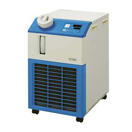
Circulating Fluid Temperature Controller
Thermo-chiller
Lightweight/Compact
Temperature stability
HRS012/018/024
Same width for all models:
Model
HRS012
HRS018
W
HRS024
HRS030
W
New
New
HRS050
W
New
New
HRS060
Compatible
power supplies
in Europe, Asia,
Oceania, North, Central
and South America
Single-phase 100 VAC (50/60 Hz),
115 VAC (60 Hz)
Single-phase 200 to 230 VAC
(50/60 Hz)
HRS
Series
New
New
377
Size
(mm)
377
615
500
x H
x D
377
660
500
x H
x D
377
976
592
x H
x D
With heating function
Convenient functions
Timer operation function/Unit conversion
function/Power failure auto-restart function/
Anti-freezing operation function
Easy maintenance
Tool-less maintenance of filter
Environmental friendly
Compact Type
HRS050
0.1
0.1
±
±
°C
°C
HRS030
mm
Cooling capacity
Weight
1300
1900
40
kg
2400
3200
47
kg
69
5100
kg
73
5900
kg
Heating method using discharged heat makes
a heater unnecessary.
Page 3
Page 3
R407C R410A
New
New
(∗ HRS030/060: Pending)
New
New
HRS060
Set temperature
range
(60 Hz)
W
W
W
5 to 40
W
W
W
Self diagnosis function
and check display
35 types of alarm codes
Communication function
Equipped with serial communication
(RS232C, RS485) and contact I/Os
(2 inputs and 3 outputs) as standard.
as refrigerant
CAT.ES40-55E
(UL Standards)
RoHS
°C
Page 4
Page 4
Advertisement
Chapters
Table of Contents

Subscribe to Our Youtube Channel
Related Manuals for SMC Networks HRS Series


Summary of Contents for SMC Networks HRS Series
- Page 1 Circulating Fluid Temperature Controller Thermo-chiller (UL Standards) Compact Type (∗ HRS030/060: Pending) RoHS Lightweight/Compact HRS050 HRS060 Temperature stability ± ± °C °C HRS012/018/024 HRS030 Same width for all models: Cooling capacity Set temperature Model Size Weight (mm) range (60 Hz) 1300 HRS012 1900...
- Page 2 Series Temperature stability ± °C/Compact The precision temperature control method by expansion valve and temperature sensor, realized high temperature stability of ±0.1°C and a small-size tank. Air-cooled HRS-A- Water-cooled HRS-W- Facility Facility water water Pressure sensor Pressure sensor Water-cooled Pressure sensor inlet...
- Page 3 Thermo-chiller Circulating Fluid Temperature Controller Temperature increase with the heating function With heating function Heating method Hot discharged using discharged heat gas from makes a heater Heater refrigerant unnecessary. Time (min) Cool fluid Cool fluid Heating functions are from from required to maintain a constant temperature refrigerant...
- Page 4 Series Reduces the maintenance Shaped for easy supply of hours for the pump. circulating fluid ∗ Adoption of the magnet pump The angled supply port facilitates the supply of circulating fluid. No external leakage of the circulating fluid because the sealless pump is used, and a periodic check of Supply is possible t h e p u m p l e a k a g e a n d r e p l a c e m e n t o f t h e even when 2 products...
- Page 5 Thermo-chiller Circulating Fluid Temperature Controller Self Diagnosis and Check Display Display of 35 types of alarm codes For details, refer to page 21. Operation is monitored all the time by the integrated sensor. Should any error occur, the self diagnosis result is displayed by the applicable alarm code from 35 types. This makes it easier to identify the cause of the alarm.
- Page 6 Series Application Examples Light electrical Heat source Automotive Food Machinery Medical Semiconductor appliance Arc welding machine Torch Resistance welding machine Laser welding machine Oscillator UV curing device Lamp ...
- Page 7 Thermo-chiller Circulating Fluid Temperature Controller Circulating Fluid/Facility Water Line Equipment Circulating Fluid Line Pressure Switch Relief valve Valve Fittings and Tubing Circulating fluid outlet User’s equipment Circulating fluid return port Y-strainer Flow Switch Facility Water Line (Water-cooled) Facility water outlet User’s equipment Facility water...
-
Page 9: Table Of Contents
Thermo-chiller Series How to Order/Specifications Page 9 Single-phase 100/115 VAC Series Page 11 Single-phase 200 to 230 VAC Cooling Capacity Page 13 Heating Capacity Page 15 Pump Capacity/ Required Facility Water Flow Rate Page 17 Dimensions Page 18 Operation Display Panel Page 21 Alarm Page 21... -
Page 10: Thermo-Chiller
Thermo-chiller Compact Type (UL Standards) Single-phase 100/115 VAC RoHS Series How to Order 018 A Air-cooled refrigeration Cooling capacity Option Cooling capacity 1100/1300 W (50/60 Hz) Symbol Option Cooling capacity 1500/1700 W (50/60 Hz) None Note) UL Standards: Applicable to 60 Hz only With earth leakage breaker Cooling method With automatic water fill function... - Page 11 Series Thermo-chiller How to Order Water-cooled refrigeration Cooling capacity Option Cooling capacity 1100/1300 W (50/60 Hz) Symbol Option Cooling capacity 1500/1700 W (50/60 Hz) None Note) UL Standards: Applicable to 60 Hz only With earth leakage breaker With automatic water fill function Cooling method Applicable to DI water (deionized water) piping Water-cooled refrigeration...
-
Page 12: Single-Phase 200 To 230 Vac
Thermo-chiller Compact Type (UL Standards) Single-phase 200 to 230 VAC Note) Refer to the CE-, UL-compliant RoHS models below. Series How to Order 018 A Air-cooled refrigeration Cooling capacity Cooling capacity 1100/1300 W (50/60 Hz) Cooling capacity 1700/1900 W (50/60 Hz) Option Cooling capacity 2100/2400 W (50/60 Hz) Symbol... - Page 13 Series Thermo-chiller How to Order 018 W Water-cooled refrigeration Cooling capacity Cooling capacity 1100/1300 W (50/60 Hz) Cooling capacity 1700/1900 W (50/60 Hz) Option Cooling capacity 2100/2400 W (50/60 Hz) Symbol Option Applicable model Cooling capacity 2600/3200 W (50/60 Hz) None Cooling capacity 4700/5100 W (50/60 Hz) With earth leakage breaker...
-
Page 14: Cooling Capacity
Series Note 1) If the product is used at altitude of 1000 m or higher, refer to “Operating Environment/Storage Environment” (page 41) Item 14 “* For altitude of 1000 m or higher”. Cooling Capacity Note 2) For a product with high-pressure pump option (-T), the cooling capacity will decrease by about 300 W from each graph. HRS012-A-10, HRS012-W-10 (Single-phase 100/115 VAC) [50 Hz]... - Page 15 Series Thermo-chiller Note 1) If the product is used at altitude of 1000 m or higher, refer to “Operating Environment/Storage Environment” (page 41) Item 14 “* For altitude of 1000 m or higher”. Cooling Capacity Note 2) For a product with high-pressure pump option (-T), the cooling capacity will decrease by about 300 W from each graph. HRS024-A-20, HRS024-W-20 (Single-phase 200 to 230 VAC) [50 Hz]...
-
Page 16: Heating Capacity
Series Heating Capacity - -10 (Single-phase 100/115 VAC) [50 Hz] [60 Hz] 1000 1000 Ambient Ambient Ambient Ambient 25°C 32°C 40°C 20°C Ambient Ambient Ambient Ambient 20°C 25°C 32°C 40°C Ambient Ambient 5°C 5°C Circulating fluid temperature [°C] Circulating fluid temperature [°C] - -20 (Single-phase 200 to 230 VAC) [50 Hz]... - Page 17 Series Thermo-chiller Heating Capacity HRS050-A-20 (Single-phase 200 to 230 VAC) [50 Hz] [60 Hz] 2000 2000 Ambient 40°C Ambient Ambient Ambient 25°C 40°C 32°C 1500 1500 1400 1100 1000 1000 Ambient Ambient Ambient Ambient Ambient Ambient 20°C 32°C 5°C 25°C 5°C 20°C Circulating fluid temperature [°C]...
-
Page 18: Pump Capacity
Series Pump Capacity - -10 - -20 (Single-phase 100/115 VAC) (Single-phase 200 to 230 VAC) 0.30 0.30 Outlet/60 [Hz] Outlet/60 [Hz] 0.25 0.25 Outlet/50 [Hz] Outlet/50 [Hz] 0.20 0.20 0.18 0.18 0.15 0.15 0.13 0.13 0.10 0.10 0.05 0.05 Return port Return port 0.00 0.00... -
Page 19: Dimensions
Series Thermo-chiller Dimensions HRS012/018/024 Ventilation air inlet Ventilation air outlet (Air-cooled only) (Air-cooled only) Maintenance connector Serial communication Handle Circulating fluid fill port lid Contact input/output (RS-485/RS-232C) connector (Same for the communication connector D-sub female receptacle Operation display panel opposite side) (21) Circulating fluid return port Rc1/2... - Page 20 Series Dimensions HRS030-W-20 Serial communication Maintenance connector (RS-485/RS-232C) connector Circulating fluid fill port lid D-sub female receptacle Handle Contact input/output Operation display panel (Same for the opposite side) communication connector (21) Optional connector 1 Fluid level indicator Circulating fluid return port Rc1/2 Optional connector 2 ∗1...
- Page 21 Series Thermo-chiller Dimensions HRS050/060-W Maintenance connector Serial communication (RS-485/RS-232C) connector Contact input/output Circulating fluid fill port lid communication connector D-sub female receptacle Operation display panel Optional connector 1 Optional connector 2 Power cable entry (Grommet with membrane) Fluid level Circulating indicator fluid return port Rc1/2...
-
Page 22: Operation Display Panel
Series Operation Display Panel The basic operation of this unit is controlled through the operation display panel on the front of the product. Description Function Displays the circulating fluid current discharge temperature and pressure and alarm codes and other menu items (codes). Digital display (7-segment and 4 digits) Displays the circulating fluid discharge temperature and the set values of other menus. -
Page 23: Communication Function
Series Thermo-chiller Communication Function Contact Input/Output Item Specifications Connector type (to the product) MC 1,5/12-GF-3,5 Insulation method Photocoupler Rated input voltage 24 VDC Input signal Operating voltage range 21.6 VDC to 26.4 VDC Rated input current 5 mA TYP Input impedance 4.7 kΩ... -
Page 24: With Earth Leakage Breaker
Series Note) Options have to be selected when Options ordering the thermo-chiller. It is not possible to add them after purchasing the unit. Option symbol With Earth Leakage Breaker Earth leakage With earth leakage breaker breaker In the event of a short circuit, overcurrent or overheating, the earth leakage breaker will automatically shut off the power supply. - Page 25 Series Options Pump Capacity HRS012/018-ll-10-T/MT Operating allowable range 0.42 0.36 Outlet: 60 Hz Outlet: 50 Hz Operating Return allowable range port Pump Circulating head fluid pressure Circulating fluid flow rate [L/min] [MPa] HRS012/018/024-ll-20-T HRS012/018/024-ll-20-MT Operating allowable range Operating Outlet: 50 Hz allowable range 0.44 Outlet: 50 Hz...
-
Page 26: High-Temperature Environment Specifications
Series Note) Options have to be selected when ordering the thermo-chiller. It is not possible to add them after purchasing the unit. Option symbol High-temperature Environment Specifications 20 G High-temperature environment specifications Makes use at ambient temperatures up to 45°C possible. Ventilation slots are added to side panels (on both sides). -
Page 28: Optional Accessories
Series Optional Accessories Applicable Model List/Air-cooled Refrigeration HRS012-A Option HRS018-A HRS024-A-20 HRS030-A-20 HRS050-A-20 Page Description Part no. HRS060-A-20 (for -J) (for -T) HRS-TK001 — — — Anti-quake bracket Page 29 HRS-TK002 — — — — — — G thread conversion fitting set HRS-EP001 —... -
Page 29: Npt Thread Conversion Fitting Set Hrs-Ep008
Series Optional Accessories Applicable Model List/Water-cooled Refrigeration HRS012-W Option HRS018-W HRS024-W-20 HRS030-W-20 HRS050-W-20 Page Description Part no. HRS060-W-20 (for -J) (for -T) HRS-TK001 — — — Anti-quake bracket Page 29 HRS-TK002 — — — — — — G thread conversion fitting set HRS-EP003 —... -
Page 30: Anti-Quake Bracket
Series q Anti-quake Bracket Bracket for earthquakes. Anchor bolt (M8) suitable for the flooring material should be prepared separately by user. (Anti-quake bracket thickness: 1.6 mm) (mm) Part no. (per unit) Applicable model HRS012-ll-l HRS018-ll-l (590) HRS-TK001 HRS024-ll-l HRS030-ll-l (581) HRS050-ll-l HRS-TK002 (698) -
Page 31: Piping Conversion Fitting (For Option)
Series Optional Accessories w Piping Conversion Fitting (For Water-Cooled Refrigeration) Conversion fitting for circulating fluid + Conversion fitting for facility water + Conversion fitting for drain outlet HRS012-W-, HRS018-W-, HRS024-W-, HRS030-W- Conversion fitting for circulating fluid This fitting changes the port size for circulating fluid from Material: Stainless steel Rc1/2 to G1/2 or NPT1/2, for facility water from Rc3/8 to G3/8 or NPT3/8, and for drain from Rc3/8 to G3/8 or NPT3/8. -
Page 32: Concentration Meter
Series r Concentration Meter This meter can be used to control the concentration of ethylene glycol aqueous solution regularly. Part no. Applicable model Approx. 170 mm HRS012-ll-l HRS018-ll-l HRS024-ll-l HRZ-BR002 HRS030-ll-l HRS050-ll-l HRS060-ll-l t By-pass Piping Set When the circulating fluid goes below the rated flow Note) To be mounted by user. -
Page 33: Power Supply Cable
Series Optional Accessories y Power Supply Cable For single-phase 100/115 VAC type ∗ Not applicable for the 200 V type. ‚ Approx. 3 m Thermo-chiller side User s equipment side Part no. Applicable model HRS012-ll-10 HRS-CA001 HRS018-ll-10 ∗ Not applicable to power supply connector locking bracket Approx. -
Page 34: Di Filter Set
Series u DI Filter Set It is possible to keep electrical resistance by flowing the circulating fluid to the ion replacement resin (DI filter). The set parts are in order to install DI filter to by-pass circuit and flow the fixed rate of the circulating fluid to DI filter. It is not to control the value of electrical resistance. -
Page 35: Electrical Resistance Sensor Set
Series Optional Accessories i Electrical Resistance Sensor Set Maintains, displays and controls electrical resistivity of the circulating fluid, DI water (Deionized water). The function differs according to the model (Refer to Table 1). Refer to the Operation Manual for details. Table 1: Combination of Option and Optional Accessories Part no. -
Page 36: Particle Filter Set
Series o Particle Filter Set Removes foreign objects in the circulating fluid. HRS PF001 W075 PF002 Accessory PF003 Accessory Filtration Symbol None Nominal filtration Element part no. for PF001/ Element part no. for PF002/ PF004 Symbol With handle accuracy (μm) PF003 (single part) PF004 (single part) Without element... -
Page 37: Drain Pan Set (With Water Leakage Sensor)
Series Optional Accessories !0 Drain Pan Set (With Water Leakage Sensor) Drain pan for the thermo-chiller. Liquid leakage from the thermo-chiller can be detected by mounting the attached water leakage sensor. Anchor bolt (M8) suitable for the flooring material should be prepared separately by user. Part no. -
Page 38: Connector Cover
*1: Displayed when optional "Electrical resistance sensor set/HRS-DI001, DI003, DI004 and DI005" are used. V Contact input/output The Run/Stop of the thermo-chiller HRS series can be operated by a contact signal. The contact signal of the operation status, alarm occurrence status and the TEMP READY status can also be output. -
Page 39: Separately Installed Power Transformer
Series Optional Accessories !4 Separately Installed Power Transformer Specifications Inlet voltage Outlet voltage Part no. Applicable model Volume Type 50 Hz 60 Hz 50 Hz 60 Hz IDF-TR1000-1 110 VAC 120 VAC IDF-TR1000-2 240 VAC 240 to 260 VAC HRS012--10 1 kVA 100 VAC 100, 110 VAC... -
Page 40: Required Cooling Capacity Calculation
Series Cooling Capacity Calculation Required Cooling Capacity Calculation Example 1: When the heat generation amount in the user’s equipment is known. The heat generation amount can be determined based on the power consumption or output of Q: Heat generation amount the heat generating area —... -
Page 41: Precautions On Cooling Capacity Calculation
Series Cooling Capacity Calculation Required Cooling Capacity Calculation Example 3: When there is no heat generation, and when cooling the object below a certain temperature and period of time. Heat quantity by cooled substance (per unit time) Q : Unknown [W] ([J/s]) Example of conventional measurement units (Reference) Cooled substance : Water... -
Page 42: Specific Product Precautions
Series Specific Product Precautions 1 Be sure to read this before handling. Refer to back cover for Safety Instructions. For Temperature Control Equipment Precautions, refer to “Handling Precautions for SMC Products” and the Operation Manual on SMC website, http://www.smcworld.com Transportation/Transfer/Movement Design Caution Warning... - Page 44 Series Specific Product Precautions 1-1 Be sure to read this before handling. Refer to back cover for Safety Instructions. For Temperature Control Equipment Precautions, refer to “Handling Precautions for SMC Products” and the Operation Manual on SMC website, http://www.smcworld.com Operating Environment/Storage Environment Warning Warning 1.
- Page 45 Series Specific Product Precautions 2 Be sure to read this before handling. Refer to back cover for Safety Instructions. For Temperature Control Equipment Precautions, refer to “Handling Precautions for SMC Products” and the Operation Manual on SMC website, http://www.smcworld.com Mounting/Installation Electrical Wiring Warning Caution...
- Page 46 Series Specific Product Precautions 3 Be sure to read this before handling. Refer to back cover for Safety Instructions. For Temperature Control Equipment Precautions, refer to “Handling Precautions for SMC Products” and the Operation Manual on SMC website, http://www.smcworld.com Facility Water Supply Operation Warning Warning...
- Page 47 Series Specific Product Precautions 4 Be sure to read this before handling. Refer to back cover for Safety Instructions. For Temperature Control Equipment Precautions, refer to “Handling Precautions for SMC Products” and the Operation Manual on SMC website, http://www.smcworld.com Maintenance Caution <Periodical inspection every one month>...
- Page 48 These safety instructions are intended to prevent hazardous situations and/or Safety Instructions equipment damage. These instructions indicate the level of potential hazard with the labels of “Caution,” “Warning” or “Danger.” They are all important notes for ∗1) safety and must be followed in addition to International Standards (ISO/IEC) and other safety regulations.
Need help?
Do you have a question about the HRS Series and is the answer not in the manual?
Questions and answers