SMC Networks HRS Series Operation Manual
Thermo chiller
Hide thumbs
Also See for HRS Series:
- Manual (48 pages) ,
- Operation manual (175 pages) ,
- Manual (2 pages)

Related Manuals for SMC Networks HRS Series


Summary of Contents for SMC Networks HRS Series
- Page 1 DOC1001322 Operation Manual Installation ・ Operation Original Instructions Thermo Chiller HRS Series HRS400-A -46- Keep this manual available whenever necessary © 2022 SMC Corporation All Rights Reserved...
- Page 2 To the users Thank you for purchasing SMC’s Thermo chiller (hereinafter referred to as the “product”). For safety and long life of the product, be sure to read this operation manual (hereinafter referred to as the “manual”) and clearly understand the contents. ●...
-
Page 3: Table Of Contents
Contact input/output communication wiring ...............3-17 3.3.5 Wiring of the Run/Stop signal input ..................3-21 3.3.6 Wiring of the contact output signal ..................3-23 3.3.7 Wiring of analog output signal ....................3-24 3.3.8 RS-485 communication wiring ...................3-24 3.3.9 RS-232C communication wiring ..................3-26 Piping ........................3-28 HRS Series... - Page 4 ・Startup operation status display START UP ................. 5-14 ・Anti-freezing status display ANTI-FREEZE .................. 5-14 ・Warming up status display WARMING UP ................... 5-14 ・Pump operation continuation status display PUMP KEEP RUN ..........5-15 ・Circulating fluid set temperature SP ..................... 5-15 HRS Series...
- Page 5 Alarm Notifications and Troubleshooting ...... 6-1 Alarm Notification ....................6-1 Operation of this product when an alarm occurs ..........6-1 Troubleshooting ...................... 6-2 6.3.1 Alarm contents, causes, and troubleshooting ..............6-2 Other Errors ......................6-5 Chapter 7 Control, Inspection and Cleaning ........7-1 HRS Series...
- Page 6 Flow Diagram ......................8-4 Cooling Capacity ...................... 8-5 Pump Capacity ......................8-5 Types of Hazard Labels ................... 8-6 8.6.1 Positions of danger warning label ..................8-7 Standards ......................... 8-8 Daily Check Sheet ....................8-9 Chapter 9 Product Warranty ............. 9-1 HRS Series...
-
Page 7: Chapter 1 Safety Instructions
1.2 Reading the Manual This manual contains symbols to help identify important actions when installing, operating or maintaining the product. This sign indicates actions that must be followed. This sign indicates prohibited actions. HRS Series 1.1 Before Using the Product... -
Page 8: Hazards
This term describes injuries that result in after effects including loss of eyesight, burns, electric shock, fracture, poisoning, etc. and requires long- term treatment or hospitalization. “Minor injury” This term describes injuries that do not need long-term treatment or hospitalization. (Others excluded from “Serious injury”.) 1.3 Hazards HRS Series... -
Page 9: Product Label
Repeated from 2023 O to Z in alphabetical A to Z in 2024 order, with O for - alphabetical January and Z for ↓ ↓ ↓ ↓ order December Fig. 1-1 Position of the product label HRS Series 1.4 Product Label... -
Page 10: Safety Measures
Handling of circulating fluid Always use safety shoes, gloves, mask, apron and eye protection when handling the circulating fluid. Operation Always use safety shoes and gloves when operating the product. 1.5 Safety Measures HRS Series... -
Page 11: Emergency Measures
1.7.2 Disposal of product The disposal of the product must be handled by a specialized industrial waste disposal agency in accordance with local laws and regulations. HRS Series 1.6 Emergency Measures... -
Page 12: Battery
1.8 Safety Data Sheet(SDS) If the safety data sheets of chemicals used in this product are needed, contact an SMC's sales distributor. Any chemicals used by the user must be accompanied by an SDS. ( ) 1.8 Safety Data Sheet HRS Series... -
Page 13: Name And Function Of Parts
NPT (Rc-NPT thread adapter set is included) ④Power supply 3phase AC380-415V(50/60Hz) 3phase AC460-480V(60Hz) ⑤Option None Caster-adjuster foot installed With electric conductivity control Fluid fill port Applicable to DI water piping Fig. 2-1 Product model number HRS Series 2.1 Model Number of Product... -
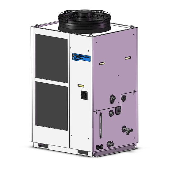
Page 14: Name And Function Of Parts
DOC1001322 Chapter 2 Name and Function of Parts 2.2 Name and Function of Parts 2.2.1 HRS400-A-46- (Air cooled type) Fig. 2-2 Names of the parts (This drawing shows “HRS400-A-46”.) 2.2 Name and Function of Parts HRS Series... - Page 15 1 The anchor brackets are used for fixation with the skid when this product is packed. The anchor bolts are not " attached. The bolts (M8) used for fixing to the skid are not anchor bolts. Refer to "3.3.1 Installation when using anchor bolt fixing bracket. HRS Series 2.2 Name and Function of Parts...
-
Page 16: Function Of Parts
Refer to “3.3.2 Electrical wiring” for the earth leakage breaker. Fluid fill port Users who will not use the automatic fluid fill function can fill the circulating (When option K “Fluid fluid without removing the panel. fill port” is selected.) 2.3 Function of Parts HRS Series... -
Page 17: Chapter 3 Transport And Setting Up
Drain the residual fluid from the piping as much as possible to prevent any spillage. When the product is carried using a forklift, make sure that the fork does not damage the cover panel or piping port. HRS Series 3.1 Transport... -
Page 18: Transportation Using Forklift And Hanging
Fig. 3-1 Fork inserting and hanging position (This drawing shows “HRS400-A-46”.) Table 3.1-1 Weight of the product Model Weight kg Option increase Option A: +14kg Option D: +1kg HRS400-A-46 Approx.340 Option K: +1kg Option M: +0kg 3.1 Transport HRS Series... -
Page 19: Transportation Using Casters
Do not hold the piping connections or handles of the panels when moving by casters, or it may cause damage to the product.. Each swivel caster can rotate 360 degrees freely. Raise the adjuster Swivel foot. caster Fig. 3-2 Transportation using casters HRS Series 3.1 Transport... -
Page 20: Installation
Location at altitude of 3000m or higher (except during product storage and transport). Refer to below for details. ● Location where the product is affected by strong vibrations or impacts. ● Condition that applies external force or weight causing the product to be damaged. 3.2 Installation HRS Series... -
Page 21: Operation At Low Ambient Temperature Or Low Circulating Fluid Temperature
- When the power supply to the Thermo-chiller is stopped for a long period of time, discharge all the circulating fluid in the Thermo-chiller and customer's device and piping. When the Thermo-chiller is refilled with the circulating fluid, supply the fluid at normal temperature. HRS Series 3.2 Installation... -
Page 22: Location
C between inside and (kW) outside of installation outside of installation area area Approx.52 HRS400-A -46- Installation environment specifications Sound noise: HRS400-A : 71 dB(A) Front 1m, height 1m, rated condition 3.2 Installation HRS Series... -
Page 23: Installation And Maintenance Space
Have enough space for product ventilation. Otherwise, it may cause a lack of cooling capacity or/and stoppage of the product. Ensure there is enough space for maintenance. 800mm or more 800mm or more Fig. 3-3 Installation space (This drawing shows “HRS400-A-46”) HRS Series 3.2 Installation... -
Page 24: Installation
Make sure that there is no looseness on any of the anchor bolts and nuts. [Tips] SMC Foundations bolt set “IDF-AB500” (SUS M10x50) is applicable. Please order separately. Hole for anchor bolt (Φ12) Bracket Base of the product Anchor bolt Hole for anchor Floor bolt (Φ12) Fig. 3-4 Installation procedures 3.3 Installation HRS Series... - Page 25 Install the product on a level floor. Lower the adjuster to the level floor to fix the product in place. Caster Lower the adjuster to the level floor to fix the product in place. Fig. 3-5 Installation by adjuster foot HRS Series 3.3 Installation...
-
Page 26: Electrical Wiring
Voltage Voltage rise % = Voltage ratio on zero-cross point Time : For the product operation in the UL compliant conditions, please refer to "Installation/Operation in accordance with the UL standard" in the next page. 3.3 Installation HRS Series 3-10... - Page 27 1 When using a power supply in the overvoltage category 3, take measures such as mounting an isolation transformer between the product and the power supply or keep the transient overvoltage of the power supply to 2500 V or less by using a varistor, etc. HRS Series 3.3 Installation 3-11...
-
Page 28: Preparation And Wiring Of Power Supply Cable
(the user’s machine power supply). When the panel is removed or mounted, be sure to wear protective shoes and gloves to prevent injury with the edge of the panel. 3.3 Installation HRS Series 3-12... - Page 29 30min 20min 14min 10min 6min 4min 2min 1min Max. Min. 0.5s 0.2s 0.1s 0.05s 0.02s 0.01s 400 500 600700 1000 1500 2000 3000 4000 Current (% for breaker capacity) Operating characteristics of the breaker HRS Series 3.3 Installation 3-13...
- Page 30 Note: Turn off the earth leakage breaker. The front panel of the electrical unit cannot be removed without turning off the breaker. Screw Fig. 3-6 Remove the front panel for the electrical unit 3.3 Installation HRS Series 3-14...
- Page 31 Hold the handle and pull up the front panel of the electrical unit, and remove it. Handle Fig. 3-7 Remove the front panel for the electrical unit Loosen the power cable outlet cap and insert the power cable. power supply cable View A Fig. 3-8 Wiring of power supply cable HRS Series 3.3 Installation 3-15...
- Page 32 Connect the power supply cable and the ground cable as shown in the figure below. View A power supply cable Fig. 3-9 Wiring of power supply cable Connect an over current protection to the power cable connected to the equipment to avoid hazard. 3.3 Installation HRS Series 3-16...
-
Page 33: Contact Input/Output Communication Wiring
The following connectors are used for this product as a contact input / output signal connector. Please prepare suitable matching connector cable. Table 3.3-2 Contact input/output communication connector Connector specification (this product side) D sub 25 pin female (socket) type Fixing bolt:M2.6×0.45 HRS Series 3.3 Installation 3-17... - Page 34 1 The total load current must be 800 mA or less. To use the power from the device, the total load current must be 200 mA or less. 2 Refer to “3.3.6 Wiring of the contact output signal” 3 For option D “With electrical conductivity control”, it can be set. 3.3 Installation HRS Series 3-18...
- Page 35 2 You cannot change the setting (“N.O type / N.C. type” can be changed). 3 Do not connect any wire For option D “With electrical conductivity control”, It is possible to change the setting. HRS Series 3.3 Installation 3-19...
- Page 36 Analog output 1 : Circulating fluid discharge temperature -15V Analog output 1 common ANALOG COM +15V 100Ω Analog output 2 : Circulating fluid discharge temperature -15V Analog output 2 common ANALOG COM Fig. 3-10 Circuit diagram 3.3 Installation HRS Series 3-20...
-
Page 37: Wiring Of The Run/Stop Signal Input
This product has three input signals. Two of them can be customized depending on the customer’s application. Prepare the switch (power supply voltage: 24 VDC, contact capacity: 35 mA or more, minimum load current: 5mA) and suitable connector cable. HRS Series 3.3 Installation 3-21... - Page 38 Pin No. Mount for cable tie 〃 Inlet of the signal 〃 cable ← Run/Stop signal 〃 Fig. 3-11 Wiring of Run/Stop signal input and remote signal input (Example) 3.3 Installation HRS Series 3-22...
-
Page 39: Wiring Of The Contact Output Signal
・Maintenance remainder signal output ・TEMP READY signal output ・TEMP OUT signal output ・START-UP setting signal output ・ANTI-FREEZING setting signal output ・WARMING- UP setting signal output ・Operation mode request signal status ・Selected alarm signal output ・Selected maintenance signal output HRS Series 3.3 Installation 3-23... -
Page 40: Wiring Of Analog Output Signal
The following connector is used for this product as a connector for RS-485 communication. Please prepare suitable mating connector. Table 3.3-7 RS-485 communication connector Connector specification D sub 9 pin female (socket) type Fixing bolt:M2.6×0.45 3.3 Installation HRS Series 3-24... - Page 41 Be sure to turn OFF the breaker of the facility power supply (the user's machine power supply) before wiring. Connecting to PC RS-485 cannot be directly connected to a normal PC. Use a RS-232C/RS485 converter which is available on the market. HRS Series 3.3 Installation 3-25...
-
Page 42: Rs-232C Communication Wiring
RS-232C communication connector The following connector is used for this product as RS-232C communication connector. Please prepare suitable matching connector. Table 3.3-8 communication connector Connector specification D sub 9 pin female (socket) type Fixing bolt:M2.6×0.45 3.3 Installation HRS Series 3-26... - Page 43 Be sure to wire as shown in the figure below. Configuration One thermo-chiller for one master. Master This product Do not connect any wire to other PIN numbers. Fig. 3-13 Connection of RS-232C HRS Series 3.3 Installation 3-27...
-
Page 44: Piping
For NPT thread, be sure to use this adapter. <For HRS400-AF46-> A set of thread adapters that converts the connections from Rc to G is enclosed as an accessory. For G thread, be sure to use this adapter. 3.3 Installation HRS Series 3-28... - Page 45 Without holding the ball valve of the drain port with a wrench, the ball valve may rotate and it may cause a fluid leakage and/or malfunction of the product. Be sure to hold the ball valve of the drain por t. HRS Series 3.3 Installation 3-29...
- Page 46 20 μm or more are Rc1/2 likely to enter, install the particle filter. Filter 20μm The filter cannot be directly connected to the thermo-chiller. Install it in the user’s piping system. 3.3 Installation HRS Series 3-30...
-
Page 47: Circulating Fluid Supply
When the ambient temperature or circulating fluid temperature is C or below, refer to "3.2.2 Operation at low ambient temperature or low circulating fluid temperature". Tap water may be frozen in the thermo-chiller which may damage the product. HRS Series 3.5 Circulating Fluid Supply 3-31... - Page 48 When using ethylene glycol aqueous solution, collect the overflowed fluid in the recycling pit and dispose it according to the local law of the country and area that the product is installed. 3.5 Circulating Fluid Supply HRS Series 3-32...
-
Page 49: Fluid Supply Without Using The Automatic Fluid Fill Function
Remove the wing nuts (4 portions) on top of the tank and remove the lid also. Note: Pay attention not to lose the wing nuts. Handles Wing nuts Seal fluid fill port Fig. 3-20 Removal of the right side panel and the lid of the fluid fill port HRS Series 3.5 Circulating Fluid Supply 3-33... - Page 50 “LOW” levels of the fluid level gauge. Fig. 3-21 supplying the fluid to the fluid fill port (An example) Confirm that the valve of the drain port is closed to prevent the supplied circulating fluid from draining out. 3.5 Circulating Fluid Supply HRS Series 3-34...
-
Page 51: Option K "Fluid Fill Port
“HIGH” and “LOW” levels of the fluid level gauge. Fig. 3-22 supplying the fluid to the fluid fill port (An example) Comfirm that the valve of the drain port is closed to prevent the supplied circulating fluid from draining out. HRS Series 3.5 Circulating Fluid Supply 3-35... -
Page 53: Chapter 4 Starting The Product
Check that the circulating fluid piping is correctly connected to the inlet and outlet. Fluid level gauge Confirm that the fluid level is between “HIGH” and “LOW” levels of the fluid level gauge. HRS Series 4.1 Before Starting... -
Page 54: Preparation For Start
The startup screen first appears on the touch panel and then switches to the operation screen (home screen). Fig. 4-1 Position of the breaker handle (This drawing shows “HRS400-A-46”) Fig.4-2 Startup screen Fig.4-3 Operation screen (home screen) 4.2 Preparation for Start HRS Series... -
Page 55: Operation Screen (Home Screen)
Items displayed on the home screen are listed in “Table 4.2-1 Items displayed on the home screen”. Refer to “Chapter 5 Display and Setting of Various Functions” for details. (10) (11) (12) (13) (14) Fig.4-4 Home screen HRS Series 4.2 Preparation for Start... - Page 56 Button Independent pump Pump operates independently while the button is (13) operation pressed. (14) Run/Stop To run/stop the product. 1 In the case of option D "With electrical conductivity control", to display the value. 4.2 Preparation for Start HRS Series...
-
Page 57: Preparation Of The Circulating Fluid Supply To The User's Equipment
] button to turn off the alarm. The displayed alarm will be turned off. After supplying the fluid, press [ button to turn off the alarm. Fig. 4-6 Turning off the low tank fluid level alarm HRS Series 4.2 Preparation for Start... - Page 58 (menu key)]to display the menu. When [ ] button is pressed, the home screen will be displayed. Touch Alarm menu screen Press Menu Home screen Fig. 4-7 Screen change from alarm menu to home screen 4.2 Preparation for Start HRS Series...
-
Page 59: Operation Start And Stop
Press the [SP] value on the touch panel (home screen) to display numeric keys to set the circulating fluid set temperature. Enter the set temperature. Touch this mark Value shown in orange Numeric keys Enter a value Fig. 4-8 Setting of circulating fluid temperature HRS Series 4.4 Operation Start and Stop... -
Page 60: Setting Of The Pump Operation Mode
Fig.4-9 Starting the product When an alarm is activated, refer to “Chapter 6 Alarm Notifications and Troubleshooting”. Ensure that the circulating fluid flow is at least the minimum required flow rate of applicable types. 4.4 Operation Start and Stop HRS Series... -
Page 61: Stopping The Product
Please turn OFF the breaker. The touch panel turns off. Except in case of an emergency, do not turn OFF the breaker before the thermo-chiller operation comes to a complete stop. As this will cause damage to the product. HRS Series 4.4 Operation Start and Stop... -
Page 62: Check Items During Startup
[Tips] Refer to “8.1 Specifications” for the minimum required flow rate. 4.4 Operation Start and Stop HRS Series 4-10... -
Page 63: Chapter 5 Display And Setting Of Various Functions
(AL10/AL11)setting screen ・ ・ Various setting screens Fig.5-1 Touch panel Be sure to operate the touch panel only with your fingers. Operating the panel with a sharp pointed screwdriver or ballpoint pen damages the panel. HRS Series 5.1 Basic Operation... -
Page 64: Basic Operating Instructions
Press Various screens Menu Press a button for example to carry out “Run/Stop,” “Selection of function” or “Change the screen. Any button-shaped section on the screen can be pressed to operate it. Button “Button” examples 5.1 Basic Operation HRS Series... - Page 65 Touch the value in orange to display numeric keys to enter a value. Enter a set value. Value shown in Numeric key Enter a value Touch this mark orange Example of an orange “Value” Example of numeric keys HRS Series 5.1 Basic Operation...
-
Page 66: Flow Chart Of The Operation Screen
Flow chart of operation screens (touch panels) of the product are shown in from Fig.5-2 Flow chart of operation screen (1/3) to Fig.5-4 Flow chart of operation screen (3/3). Fig.5-2 Flow chart of operation screen (1/3) 5.2 Flow Chart of the Operation Screen HRS Series... - Page 67 DOC1001322 Chapter 5 Display and Setting of Various Functions Fig.5-3 Flow chart of operation screen (2/3) HRS Series 5.2 Flow Chart of the Operation Screen...
- Page 68 DOC1001322 Chapter 5 Display and Setting of Various Functions Fig. 5-4 Flow chart of operation screen (3/3) 5.2 Flow Chart of the Operation Screen HRS Series...
-
Page 69: List Of Functions
Analogue output Sets the analogue output. 5.4.9 Contact input signal Sets the contact input signal. Contact output signal Sets the contact output signal. 1 Only for Option D "With electrical conductivity control" HRS Series 5.2 Flow Chart of the Operation Screen... -
Page 70: Description Of The Screen
Chapter 5 Display and Setting of Various Functions 5.4 Description of the Screen 5.4.1 Home screen Items displayed on the home screen and setting items are shown in Table 5.4-1 List of check items in inspection monitor menu. Home screen 5.4 Description of the Screen HRS Series... -
Page 71: Menu Key
( mode). Independent pump Pump operates independently while the button is (20) P.5-16 operation pressed. 1 In the case of option D “With electrical conductivity control", to display the value. HRS Series 5.4 Description of the Screen... -
Page 72: Display And Setting Of Date And Time
Home screen Date and time entry screen ・Current circulating fluid temperature [PV]Circulating fluid set temperature [SP] Display the current circulating fluid temperature. Current circulating fluid temperature Current circulating fluid temperature 5.4 Description of the Screen HRS Series 5-10... -
Page 73: Operating Condition Display
Displays the run and stop status of the compressor. During operation Stopped ON/OFF compressor status display ・Pump operating condition display Displays the run and stop status of the pump. During operation Stopped ON/OFF pump status display HRS Series 5.4 Description of the Screen 5-11... -
Page 74: Tank Fluid Level
Circulating fluid discharge pressure Circulating fluid discharge pressure ・Compressor circuit High pressure side High Press. Displays the High pressure side of refrigeration circuit. Compressor circuit High pressure side Compressor circuit High pressure side 5.4 Description of the Screen HRS Series 5-12... -
Page 75: Compressor Circuit Low Pressure Side Low Press
] lights up when KEY-LOCK setting is ON. (Refer to “KEY-LOCK, START-UP operating method, ANTI-FREEZING and WARMING-UP”(P.5-42) for the setting of KEY-LOCK.) KEY-LOCK setting is ON KEY-LOCK setting is ON Key lock condition display KEY-LOCK setting is OFF HRS Series 5.4 Description of the Screen 5-13... -
Page 76: Startup Operation Status Display Start Up
] lights up when WARMING-UP setting is ON. (Refer to “KEY-LOCK, START-UP operating method, ANTI-FREEZING and WARMING- UP”(P.5-42) for the setting of warm-up.) WARMING-UP setting is ON WARMING-UP setting is OFF Warming up status display 5.4 Description of the Screen HRS Series 5-14... -
Page 77: Pump Operation Continuation Status Display Pump Keep Run
The set temperature ranges are as follows: Circulating fluid Item temperature SP Setting range 5℃ to 35℃ By default 20℃ In the case of out of the setting range, and displays an error message. Set temperature error HRS Series 5.4 Description of the Screen 5-15... -
Page 78: Operation Mode Mode
Operation mode selection Operation mode 12.温度設定画面 screen 13.運転モード選択画面 ・Independent pump operation Pump [ ]Pump operates independently while the button is pressed. Pump operates independently while the button is pressed. Independent pump operation 5.4 Description of the Screen HRS Series 5-16... -
Page 79: Run/Stop Operation
・If the “Operation mode” is set to anything other than “LOCAL”, a “Switch to the local mode” message appears. Set the running mode to the “LOCAL” mode. Switch to the local mode Cannot run because of the fault alarm HRS Series 5.4 Description of the Screen 5-17... -
Page 80: Menu
Press [ ] button on the menu to display “Status” screen. The screen display of the “Status” screen is shown in “Table 5.4-2 Screen display of status screen”. Press Menu (10) Status screen 5.4 Description of the Screen HRS Series 5-18... -
Page 81: Information Screen
・To reset an alarm. (An alarm cannot be reset without first eliminating the cause. Refer to “Chapter 6 Alarm Notifications and Troubleshooting” for details.) ・To display previously activated alarms (alarm history). Press Menu Information screen HRS Series 5.4 Description of the Screen 5-19... - Page 82 ] is displayed upper right on the screen if an “Alarm” is activated or a “Maintenance reminder” is issued. The number shows the number of activated “Alarms” or issued “Maintenance reminders” Display when an “Alarm” is activated or “Maintenance reminder” is issued 5.4 Description of the Screen HRS Series 5-20...
-
Page 83: Alarm Reset
If the alarm utilizes a sub-code, this is displayed in the alarm information details. Touch once Touch twice to go to alarm to select alarm information details Information screen If the alarm utilizes a sub-code, that subcode is displayed. Alarm information details HRS Series 5.4 Description of the Screen 5-21... -
Page 84: Alarm Log Record
・Cleaning of alarm history All “Alarmˮ records are cleared if the “History Clearˮ button is pressed. However, the currently activated alarm is not cleared. Press Press Alarm history screen Clearing of alarm history 5.4 Description of the Screen HRS Series 5-22... -
Page 85: Display Of Alarm/Maintenance Reminder
The “Alarm” and “Maintenance reminder” on the “Information” screen can each be individually displayed. Press Button Description Displays both alarm and maintenance reminder. Displays alarm only. Displays maintenance reminder only. By default: It is set to “Alarm Maint.” Information screen HRS Series 5.4 Description of the Screen 5-23... -
Page 86: Check Operation Time Screen And Maintenance Reminder
Screen display and function of the “Check operation time” screen are shown in “Table 5.4-3 Screen display of check operation time screen”. Press Menu Operation time of each component Displayed for option D Operation time of the product Check operation time screen 5.4 Description of the Screen HRS Series 5-24... - Page 87 Communication setting screen (Refer to “5.4.9 Communication setting screen” for details.) ・A “Maintenance reminder” signal can be output as “The AL36: Maintenance alarm”. (Refer to “5.4.8 Ambient temperature alarm [AL35] and Maintenance Alarm [AL36]”.) HRS Series 5.4 Description of the Screen 5-25...
-
Page 88: Setting The Usage Time Of Di Filter
The replacement period (usage time) for a dustproof filter can be set. “Maintenance reminderˮ is always issued when the filter reaches the specified time. Touch the numeric Touch Check operation time screen Enter the usage time 5.4 Description of the Screen HRS Series 5-26... -
Page 89: Software Version Screen
Setting screen for TEMP READY alarm (AL12) of TEMP READY ・ function Setting screen for TEMP OFFSET ・ Setting screen for pump operation mode ・ Setting screen for discharge pressure alarm (AL18/AL19/AL20) ・ Setting screen for electric conductivity (AL28) ・ HRS Series 5.4 Description of the Screen 5-27... -
Page 90: Temperature Rise/Drop Alarm (Al10/Al11)
The alarm is activated when the set time has passed after the 0 to 600sec Out Time Out time [Out Time] temperature rises/drops out of the 5sec alarm setting range. By default. 5.4 Description of the Screen HRS Series 5-28... - Page 91 Circulating fluid set temperature 20ºC 400sec AL11 set °C temperature 18 AL10 alarm monitoring AL11 alarm monitoring Generate Alarm AL10 No alarm Generate Alarm AL11 No alarm Time Fig. 5-5 Alarm monitoring timing HRS Series 5.4 Description of the Screen 5-29...
-
Page 92: Temp Ready Alarm (Al12) Of Temp Ready Function
It can be set on “TEMP READY function setting” screen. Refer to “Table 5.4-5 TEMP READY signal setting (P.5-31) and “■About TEMP READY function” (P.5-32) for details. TEMP READY signal (AL12) setting 5.4 Description of the Screen HRS Series 5-30... - Page 93 Start time of READY alarm” starts when 0sec to 9999sec Start Time AL12 alarm [Start Time] 600sec the set time has passed monitoring after the start of operation. By default. HRS Series 5.4 Description of the Screen 5-31...
- Page 94 Time” range of 200 sec even though it was temporarily outside the “Low” range. Status (7): “TEMP READY” signal turns OFF when 200 sec has passed after the temperature rises above the “High” range. “TEMP READY alarm (AL12)” is simultaneously activated. 5.4 Description of the Screen HRS Series 5-32...
-
Page 95: Offset (Temp Offset) Function
(MODE1 to 3). The default setting of this function is “OFF”. 【When communication is used】 The circulating fluid temperature sent by serial communication is the circulating fluid temperature which is displayed on the thermo-chiller (the circulating fluid temperature after offset). HRS Series 5.4 Description of the Screen 5-33... - Page 96 Circulating fluid display temperature and communication data is 31 This produuct Your system Circulating fluid temperature 31℃ Serial communication Discharge temperature 31℃ Circulating fluid display temperature 31℃ Heat radiation Circulating fluid set 1℃ temperature 30℃ Offset temperature 30℃ 1℃ 5.4 Description of the Screen HRS Series 5-34...
- Page 97 - offset temp.), and matches the circulating fluid temperature at the customer's device. This produuct Your system Circulating fluid temperature 30℃ Serial communication Discharge temperature 31℃ Circulating fluid display temperature 30℃ Heat radiation Circulating fluid set 1℃ temperature 30℃ Offset temperature 30℃ 1℃ HRS Series 5.4 Description of the Screen 5-35...
-
Page 98: Pump Operation Mode
] is displayed on the upper screen when the pump discharge pressure is controlled during operation. (Refer to “5.4.1 Operation condition display on home screen”.) This can be set on “Pump operation mode setting” screen. Refer to “Table 5.4-7 Pump operation settings for details”. 5.4 Description of the Screen HRS Series 5-36... -
Page 99: Discharge Pressure Alarm (Al18/Al19/Al20)
] (disabled) or ] (operation continues at time of alarm), the pump operation mode switches to the “Pump output setting modeˮ (50% output) to continue operation when a pressure sensor failure is detected. HRS Series 5.4 Description of the Screen 5-37... - Page 100 Operation stops during pressure drop alarm Disabled AL18: Failure Press. Operation continues of circulating Sensor - during the alarm fluid discharge Alarm pressure sensor Operation stops during alarm By default 5.4 Description of the Screen HRS Series 5-38...
-
Page 101: Electric Conductivity And Alarm Setting (Al28)
“AL28” automatically turns off the alarm 0.4 to 46.0μS/cm of Electrical Conductivity when the electrical conductivity falls below conductivity 45.0μS/cm Alarm the set value. increase alarm Disabled Operation continues during the alarm By default HRS Series 5.4 Description of the Screen 5-39... - Page 102 • Electrical conductivity control hysteresis : 5.0 [µS / cm] Electric conductivity [μS/cm] Target electrical conductivity value Electric conductivity Solenoid valve : Open Solenoid valve : Close Elapsed time Fig.5-7 Example of electrical conductivity control 5.4 Description of the Screen HRS Series 5-40...
-
Page 103: Function Setting Screen
Setting screen for continuing pump operation ・ ・ Setting screen for ambient temperature alarm (AL35) and maintenance alarm (AL36) Setting screen for TEMP OUT signal ・ Setting screen for data reset ・ HRS Series 5.4 Description of the Screen 5-41... -
Page 104: Key-Lock, Start-Up Operating Method, Anti-Freezing And Warming-Up
Fully open the valve or manual by-pass valve that was installed by the user to let the circulating fluid circulate when the pump operation automatically starts. Setting of KEY-LOCK, START-UP operation, ANTI-FREEZING and WARMING-UP 5.4 Description of the Screen HRS Series 5-42... -
Page 105: Continuing Pump Operation
“Continuous pump operation” ends 0 to 9999sec Pump operation when the set time has elapsed. Time sustainable time Set time: 0 sec––this function is 0sec “Disabled” By default HRS Series 5.4 Description of the Screen 5-43... - Page 106 HX In High Temp. FLT AL17 [FLT] [OFF] / [WRN] Press. Sensor AL18 × [FLT] [OFF] / [WRN] High Press. AL19 × [FLT] [OFF] / [WRN] Low Press. AL20 ○ [FLT] Default setting. 5.4 Description of the Screen HRS Series 5-44...
- Page 107 [FLT] × AL42 Pump Inverter [FLT] × AL43 Pump Inverter Comm. [FLT] Default setting. ・“FLT” : Operation stops when alarm occurs; “WRN”: operation continues when alarm occurs; “OFF”: alarm is disabled. HRS Series 5.4 Description of the Screen 5-45...
-
Page 108: Ambient Temperature Alarm (Al35) And Maintenance Alarm (Al36)
45ºC. the alarm Disabled If “WRN” is selected, the AL36: alarm “AL36” activates Maintenance Maintenance Operation when “Maintenance alarm continues during reminder” is issued. the alarm By default 5.4 Description of the Screen HRS Series 5-46... -
Page 109: Temp Out Signal
Alarm “AL10: circulating fluid Alarm temperature rise” Enabled Disabled Low Temp. Alarm “AL11: circulating fluid Alarm temperature drop” Enabled Disabled TEMP READY Alarm “AL12: TEMP READY alarm” Alarm Enabled By default HRS Series 5.4 Description of the Screen 5-47... -
Page 110: Data Reset
“Date and time,” “Operation time” and “Alarm history” are not reset. Data reset setting screen Table 5.4-16 Data reset setting Indication Item Explanation All Setting Set values are reset to default Data reset Reset settings. 5.4 Description of the Screen HRS Series 5-48... -
Page 111: Communication Setting Screen
Setting screen for analog output ・ ・ Setting screen for contact input signal form ・ Setting screen for contact output signal 1 to 3 ・ Setting screen for contact output signal 4 to 6 HRS Series 5.4 Description of the Screen 5-49... -
Page 112: Setting For Communication Error (Al34)/Contact Input Signal Detection (Al30 And Al31)
This function is set to “Disabled” by default. Refer to “Setting of contact input signal form” (P.5–54) for details. Contact input signal can be used to perform the “Run/Stop” of the product. Refer to “Setting of contact input signal form” (P.5–54) for the setting method. 5.4 Description of the Screen HRS Series 5-50... - Page 113 To readout the status of respective parts of the product (e.g., operation status and content of alarm) This section describes the operation of the “Serial communication setting” screen. Refer to “Communication Function” of Operation Manual for details such as for communication messages. HRS Series 5.4 Description of the Screen 5-51...
-
Page 114: Serial Communication Setting
2 “Run/stop” operation of the product is carried out by the contact input signal, and by reading/writing the “Change in set value of circulating fluid temperature” and “Operation status” by serial communication. 5.4 Description of the Screen HRS Series 5-52... -
Page 115: Setting Of Analog Output Signal
0.1~50.0μS/cm:0.02~10.0V electric conductivity Circulating fluid 0~100℃:0~10V Analog discharge temperature Analog output signal 2 Output 2 Circulating fluid 0.1~50.0μS/cm:0.02~10.0V electric conductivity 1 By default 2 Option D" With electrical conductivity control" only. HRS Series 5.4 Description of the Screen 5-53... -
Page 116: Setting Of Contact Input Signal Form
(normally closed) 1 By default. 2 This setting assigns “Run” signal to “Contact input 1” and “Stop” signal to “Contact input 2”. 3 The signal form of contact input 3 is “Momentary”. 5.4 Description of the Screen HRS Series 5-54... -
Page 117: Setting Of Contact Output Signal 1 To 3
Contact output signal 4––selects “Signal type” and “N.O.” (A contact ) or “N.C.” (B contact). ・ Contact output signal 5––selects “Signal type” and “N.O.” (A contact ) or “N.C.” (B contact). ・ Contact output signal 6––selects “Signal type” and “N.O.” (A contact) or “N.C.” (B contact). HRS Series 5.4 Description of the Screen 5-55... -
Page 118: Setting Of Contact Output Signal 4 To 6
B contact Function signal 5 contact output signal (normally closed) 4 to 6” [Off] A contact (normally open) Output 6 Contact output B contact Function signal 6 (normally closed) By default 5.4 Description of the Screen HRS Series 5-56... - Page 119 Refer to "Table 5.4-25 List of alarm selection" for selectable alarms. Selected maintenance Maintenance remainders reminders occurred:closed status signal Selected maintenance 18 Select Maintenance reminders occurred:open About selectable maintenance remainders Refer to "Table 5.4-26 List of maintenance reminders". HRS Series 5.4 Description of the Screen 5-57...
- Page 120 DI Filter (Option D only) 1 Refer to “5.4.5 Check operation time screen and maintenance reminder” for “Maintenance reminder”. 2 In the case of option D "With electrical conductivity control", to display. 5.4 Description of the Screen HRS Series 5-58...
-
Page 121: Temperature Waveform Screen
“Time scroll” button. Button Time scroll Press this button to shift the time axis forward. Temperature Change of A value can be entered to change the range temperature range temperature range for temperature waveform. HRS Series 5.4 Description of the Screen 5-59... -
Page 123: Chapter 6 Alarm Notifications And Troubleshooting
DOC1001322 Chapter 6 Alarm Notifications and Troubleshooting Chapter 6 Alarm Notifications and Troubleshooting 6.1 Alarm Notification The product makes notifications in the order shown below when any alarm is generated. The screen automatically moves to the "Information" screen and displays alarm codes and alarm contents. -
Page 124: Troubleshooting
DOC1001322 Chapter 6 Alarm Notifications and Troubleshooting 6.3 Troubleshooting 6.3.1 Alarm contents, causes, and troubleshooting Troubleshooting method varies depending on which alarm has been generated. Refer to “Table 6.3-1 and 6.3-2 Alarm codes and troubleshooting”. Instructions to reset the alarms after eliminating the causes of the alarms explained below. - Page 125 DOC1001322 Chapter 6 Alarm Notifications and Troubleshooting Table 6.3-1 Alarm codes and troubleshooting (1/2) Alarm content Default setting Alarm Cause/Countermeasure code (Please reset the alarm after eliminating the cause.) Sub code Operation Threshold - AL01 Low Level FLT The circulating fluid level has decreased. -...
- Page 126 DOC1001322 Chapter 6 Alarm Notifications and Troubleshooting Table 6.3-2 Alarm codes and troubleshooting (2/2) Alarm content Default setting Alarm Cause/Countermeasure code (Please reset the alarm after eliminating the cause.) Sub code Operation Threshold - Maintenance 1 Pump maintenance 20,000h 2 Compressor maintenance 30,000h 3 Fan maintenance 30,000h...
-
Page 127: Other Errors
DOC1001322 Chapter 6 Alarm Notifications and Troubleshooting 6.4 Other Errors How to check other errors Possible causes and countermeasures for failures with no alarm code display are shown in ’’Table 6.4-1” Table 6.4-1 Possible causes and countermeasures for failures without alarm code Content of Possible cause Countermeasure... -
Page 129: Chapter 7 Control, Inspection And Cleaning
DOC1001322 Chapter 7 Control, Inspection and Cleaning Chapter 7 Control, Inspection and Cleaning 7.1 Quality Control of Circulating Fluid and Facility Water Use specified fluids only. If other fluids are used, they may damage the product, causing fluid leakage, or result in hazards such as electric shock or leakage of electricity. -
Page 130: Inspection And Cleaning
DOC1001322 Chapter 7 Control, Inspection and Cleaning 7.2 Inspection and Cleaning Do not perform key operation or setting of this equipment with wet hands. Do not touch the electrical parts such as the power supply plug. It may cause an electric shock. ... -
Page 131: Daily Check
DOC1001322 Chapter 7 Control, Inspection and Cleaning 7.2.1 Daily check Check the items listed below. If any abnormality is found, stop the operation of the product and turn the power supply OFF, and ask for service. Table 7.2-1 Daily check items Item Contents of check ・Check that there is no heavy object on the product or... - Page 132 DOC1001322 Chapter 7 Control, Inspection and Cleaning Removal of the dust-proof filter The dust-proof filters are installed on the front and left sides of the product. They can be removed as shown in the drawing below. Care should be taken not to deform or scratch the air cooled condenser (fins) while removing the filters.
-
Page 133: Inspection Every 3 Months
DOC1001322 Chapter 7 Control, Inspection and Cleaning Mounting of dust-proof filters Reassemble the filters in the reverse order to the removing procedure. 7.2.3 Inspection every 3 months Table 7.2-3 Contents of every 3 months check Item Contents of check Check the power supply Make sure the supply voltage is within the Power supply... -
Page 134: Inspection During Winter Season
DOC1001322 Chapter 7 Control, Inspection and Cleaning 7.2.4 Inspection during winter season Keep the power supply ON for these functions. These functions do not start when the power is OFF. Anti-freezing function This function prevents freezing of the circulating fluid while the product stops operation in the winter season with heat generated by automatically operating the pump. -
Page 135: Operation Stop For An Extended Period Of Time
DOC1001322 Chapter 7 Control, Inspection and Cleaning 7.3 Operation Stop for an Extended Period of Time If there is a concern that the product will not be operated for an extended period of time or there is a possibility of freezing during winter time, take measures according to the instructions shown below. - Page 136 DOC1001322 Chapter 7 Control, Inspection and Cleaning 【For Option D】 Remove the DI filter. 1) Remove the maintenance panel and remove the DI filter. (Refer to “7.4.1 Replacing the DI filter”.) Store the removed DI filter separately. 2) Install the DI filter temporary piping that was installed at the time of delivery. Install temporary piping for DI filter...
-
Page 137: Replacement Of Consumables
DOC1001322 Chapter 7 Control, Inspection and Cleaning 7.4 Replacement of consumables Before discharging the circulating fluid, stop the user’s equipment and release the residual pressure. Be sure to wear protective shoes and gloves to prevent injury with the edge of the panel. Replacing the DI Filter 【For Option D】... - Page 138 DOC1001322 Chapter 7 Control, Inspection and Cleaning Remove DI filter fixed band by pushing lever on the band. (The temporary piping for DI filter is connected at the time of delivery. "Temporary piping for DI filter" is used for long term storage of this product. Please keep it in a safe place.) Fixed band Press Lever...
-
Page 139: Consumables
DOC1001322 Chapter 7 Control, Inspection and Cleaning The connection fitting of the DI filter and the tube is connected by a fastener. O ring is used for the connection fitting. After removing the fastener, remove the connection fitting. Be careful not to apply force to the tube at this time. Also, please be careful not to damage the O ring. -
Page 141: Chapter 8 Documents
(5) Circulating fluid flow rate: Rated flow rate, (6) Power supply: 400 VAC, (7) Piping length: Minimum 6 With the pressure control mode that controls the pressure automatically with the inverter.If the pressure control mode is not necessary,use the flow control function or the pump output setting function. HRS Series 8.1 Specifications... -
Page 142: Refrigerant With Gwp Reference
1. This product is hermetically sealed and contains fluorinated greenhouse gases. 2. See specification table for refrigerant used in the product. 8.1.3 Communication specifications For contact input/output communications, refer to 3.3.4 Contact input/output communication wiring 8.1 Specifications HRS Series... -
Page 143: Dimensions
DOC1001322 Chapter 8 Documents 8.2 Dimensions Dimensions for the positions of the anchor bolts (View A) Fig. 8-1 Dimensions (This drawing shows “HRS400-A-46”) HRS Series 8.2 Dimensions... -
Page 144: Flow Diagram
DOC1001322 Chapter 8 Documents 8.3 Flow Diagram : Option D “With electrical conductivity control” only Fig. 8-2 Flow Diagram (HRS400-A-46-) 8.3 Flow Diagram HRS Series... -
Page 145: Cooling Capacity
DOC1001322 Chapter 8 Documents 8.4 Cooling Capacity Fig. 8-3 Cooling Capacity (HRS400-A-46-) 8.5 Pump Capacity Circulating fluid outlet Usable flow rate range Circulating fluid return Circulating fluid flow [L/min] Fig. 8-4 Pump capacity(HRS400-A-46-) HRS Series 8.4 Cooling Capacity... -
Page 146: Types Of Hazard Labels
Rotary fan: This product has a rotating object inside the cover panel. <Water-cooled refrigerated type> High pressure inside: This product contains high pressure liquid in the piping and the tank. Do not operate the product without the cover panels mounted. 8.6 Types of Hazard Labels HRS Series... -
Page 147: Positions Of Danger Warning Label
Confirm the positions of the danger warning labels on the product to show the potential danger before starting operation. Fig. 8-5 Positions of danger warning label Fig. 8-6 Positions of danger warning label HRS Series 8.6 Types of Hazard Labels... -
Page 148: Standards
DOC1001322 Chapter 8 Documents 8.7 Standards This product complies with the standards shown below: Table 8.7-1 Standards Standard EMC Directive 2014/30/EU CE Mark Machinery Directive 2006/42/EC NRTL E112803(UL61010-1) 8.7 Standards HRS Series... -
Page 149: Daily Check Sheet
DOC1001322 Chapter 8 Documents 8.8 Daily Check Sheet HRS Series 8.8 Daily Check Sheet... -
Page 151: Chapter 9 Product Warranty
(4) Expenses for replacement of parts other than those in this product, or for the supply of liquids (5) Inconvenience and loss due to product failure (such as telephone bills, compensation for workplace closure, and commercial losses) (6) Expenses and compensation not covered in “2. Scope”. HRS Series Product Warranty... - Page 152 Repair shall be provided free of charge in accordance with the warranty period, preconditions and terms defined above. Therefore, a fee will be charged for any repairs if a failure is detected after the end of the warranty period. Product Warranty HRS Series...
- Page 153 Revision 4-14-1, Sotokanda, Chiyoda-ku, Tokyo 101-0021 JAPAN Tel: + 81 3 5207 8249 Fax: +81 3 5298 5362 https://www.smcworld.com Note: Specifications are subject to change without prior notice and any obligation on the part of the manufacturer. © 2022 SMC Corporation All Rights Reserved...
Need help?
Do you have a question about the HRS Series and is the answer not in the manual?
Questions and answers