Sign In
Upload
Manuals
Brands
SMC Networks Manuals
Chiller
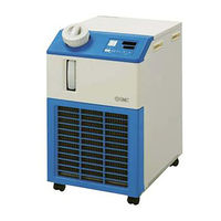
HRS030-W-20 Series
SMC Networks HRS030-W-20 Series Manuals
Manuals and User Guides for SMC Networks HRS030-W-20 Series. We have
1
SMC Networks HRS030-W-20 Series manual available for free PDF download: Service Manual
SMC Networks HRS030-W-20 Series Service Manual (222 pages)
Thermo-chiller
Brand:
SMC Networks
| Category:
Chiller
| Size: 7 MB
Table of Contents
Table of Contents
3
Chapter 1 Safety Instructions
7
Before Using Unit
7
Reading the Manual
7
Hazards
8
Level of Hazards
8
Definition of "Serious Injury" and "Light Injury
8
Types of Hazard Labels
9
Locations of Hazard Labels
10
Other Labels
11
Product Label
11
Safety Measures
11
Safety Instructions for Use
11
Waste Disposal
12
Disposal of Refrigerant and Compressor Oil
12
Disposal of Product
12
Material Safety Data Sheet (MSDS)
12
Chapter 2 Name of Parts
13
Appearance
13
Component Parts
15
Chapter 3 Alarm Indication and Troubleshooting
17
Alarm Display
17
Error Type and Alarm Set Value
18
How to Reset Alarm
20
Troubleshooting
21
How to Use the Flow Chart of Troubleshooting
21
Icons for Necessary Tools and Specifications
22
Removal and the Mounting of the Panel
23
Troubleshooting of Alarms
25
AL01: Low Level in Tank
25
AL02: High Circulating Fluid Discharge Temp. [For Air-Cooled Type]
27
AL02: High Circulating Fluid Discharge Temp. [For Water-Cooled Type]
36
AL03: Circulating Fluid Discharge Temp. Rise
45
AL04: Circulating Fluid Discharge Temp. Drop
46
AL05: High Circulating Fluid Return Temp
48
AL06: High Circulating Fluid Discharge Pressure
50
AL07: Abnormal Pump Operation
53
AL08: Circulating Fluid Discharge Pressure Rise
58
AL09: Circulating Fluid Discharge Pressure Drop
61
AL10: High Compressor Intake Temp
62
AL11: Low Compressor Intake Temp
64
AL12: Low Super Heat Temperature
67
AL13: High Compressor Discharge Pressure [For Air-Cooled Type]
72
AL13: High Compressor Discharge Pressure [For Water-Cooled Type]
80
AL15: Refrigerant Circuit Pressure (High Pressure Side) Drop
87
AL16: Refrigerant Circuit Pressure (Low Pressure Side) Rise
92
AL17: Refrigerant Circuit Pressure (Low Pressure Side) Drop
96
AL18: Compressor Overload [For Air-Cooled Type]
101
AL18: Compressor Overload [For Water-Cooled Type]
106
AL19: Communication Error
111
AL20: Memory Error
111
AL21: DC Line Fuse Cut
112
AL22: Circulating Fluid Discharge Temp. Sensor Failure
112
AL23: Circulating Fluid Return Temp. Sensor Failure
114
AL24: Compressor Intake Temp. Sensor Failure
116
AL25: Circulating Fluid Discharge Pressure Sensor Failure
119
AL26: Compressor Discharge Pressure Sensor Failure
121
AL27: Compressor Intake Pressure Sensor Failure
123
AL28: Maintenance of Pump
125
AL29: Maintenance of Fan Motor [For Air-Cooled Type]
125
AL30: Maintenance of Compressor
125
AL31: Contact Input1 Signal Detection
126
AL32: Contact Input 2 Signal Detection
126
AL33: Water Leakage
127
AL34: Electric Resistivity/Conductivity Rise
128
AL35: Electric Resistivity/Conductivity Drop
128
AL36: DI Sensor Error
129
Troubleshooting of Errors Without Alarm Generation
130
The Circulating Fluid Temperature Does Not Go down
130
The Circulating Fluid Temperature Does Not Go up
130
The Operation Panel Displays Nothing
130
Impossible to Operate the Thermo-Chiller with the "RUN/STOP" Key on the Operation Panel
132
Lights on the Operation Panel or Display(S) on the Digital Display Does Not Operate
132
The Alarm Buzzer Does Not Sound
133
Facility Water Does Not Flow (for Water-Cooled Type)
133
Automatic Water Fill Does Not Operate (for Option J "Automatic Water Fill Specification")
134
Precautions for Whole Work
137
Preparation for Work
137
Check after Work
137
Chapter 4 Service Procedure
137
Work Procedure
138
Removal and the Mounting of the Panel
138
Discharge of the Circulating Fluid and Facility Water
140
Check after Work
144
Starting the Product
144
Stopping the Product
144
Check Items after Starting
145
Icons for Necessary Tools and Specifications
146
Replacement Procedure
148
Replacement of Temperature Sensor (PT1)
148
Replacement of Temperature Sensor (PT2)
150
Replacement of Pump (for Standard Pump)
152
Replacement of High Pressure Pump
155
Replacement of Mechanical Seal Set
159
Replacement of Fan
163
Replacement of Level Switch
166
Replacement of Pressure Sensor
168
Replacement of Dustproof Filter
169
Replacement of Front Panel
170
Replacement of Tank
174
Replacement of Tank (for Automatic Water Fill)
176
Replacement of Inlet Socket
178
Replacement of Power Switch
180
Replacement of DC Power Supply
182
Replacement of Main Board & Communication Board
184
Replacement of Power Board
186
Replacement of Display Board
190
Replacement of Hose
191
Replacement of Fuse
197
Replacement of Valve for Automatic Water Fill
198
Chapter 5 Service Parts List
201
Before Using Service Parts List
201
Numbering System Chart
201
Service Parts List
202
Illustration of Service Parts
204
Dustproof Filter
204
Panel
204
Temperature Sensor
205
Hose
205
Pressure Sensor (for Circulating Fluid)
206
Level Switch
206
DC Power Supply
207
Main Board / Communication Board / Power Board / Display Board / Fuse
208
Power Switch
209
Inlet Socket
209
Pump
210
Fan
210
Tank
211
Tank Lid
211
Valve for Automatic Water Fill
212
Chapter 6 Documents
213
Specifications List
213
Outline Dimensions
216
Electric Circuit Diagram
218
Hrs0
218
Flow Chart
219
Chapter 7 Product Warranty
221
Advertisement
Advertisement
Related Products
SMC Networks HRS030-A-20 Series
SMC Networks HRS030
SMC Networks HRS030-A Series
SMC Networks HRS050-A*-20 Series
SMC Networks Series HRS012-A
SMC HRS090-W...-40 Series-?
SMC HRS050-A
SMC HRS012-W
SMC HRS024-W
SMC Networks HRS090 Series
SMC Networks Categories
Switch
Control Unit
Controller
Industrial Equipment
Network Router
More SMC Networks Manuals
Login
Sign In
OR
Sign in with Facebook
Sign in with Google
Upload manual
Upload from disk
Upload from URL