Table of Contents
Advertisement
Quick Links
Advertisement
Table of Contents
Troubleshooting

Related Manuals for SMC Networks HRSE018-A


Summary of Contents for SMC Networks HRSE018-A
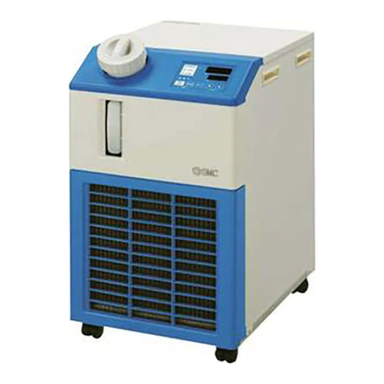
- Page 1 HRX-OM-R039 edition: Dec. 2013 Rev.E: Feb. 2017 Operation Manual Installation・Operation Original Instructions Thermo chiller Air-Cooled refrigerated type HRSE012/018/024 Series [ HRSE012/018/024-A-23(-T) Keep this manual available whenever necessary © 2017 SMC CORPORATION All Rights Reserved...
- Page 2 To the users Thank you for purchasing SMC’s Thermo chiller (hereinafter referred to as the “product”). For safety and long life of the product, be sure to read this operation manual (hereinafter referred to as the “manual”) and clearly understand the contents. ...
-
Page 3: Table Of Contents
HRX-OM-R039 Contents Contents Chapter 1 Safety Instructions ............1-1 Before using the product ..................1-1 Reading the Manual ....................1-1 Hazards ........................1-2 1.3.1 Level of hazards ........................1-2 Definition of “Serious injury” and “Minor injury” ..............1-2 1.3.2 1.3.3 Types of hazard labels ...................... - Page 4 HRX-OM-R039 Contents 4.2.1 Power supply ........................4-2 4.2.2 Setting of circulating fluid temperature ................4-2 Preparation of circulating fluid ................4-3 Starting and Stopping ....................4-5 4.4.1 Starting the product ......................4-5 4.4.2 Stopping the product ......................4-6 Check items after starting ..................4-7 Adjustment of Circulating Fluid ................
- Page 5 Refrigerant with GWP reference ..................8-4 Outline dimensions ....................8-5 Flow chart ........................ 8-6 Cooling capacity ...................... 8-7 8.4.1 HRSE012-A-10-(T) ......................8-7 8.4.2 HRSE018-A-10-(T) ......................8-7 8.4.3 HRSE012-A-20/23-(T) ......................8-7 8.4.4 HRSE018-A-20/23-(T) ......................8-8 8.4.5 HRSE024-A-20/23-(T) ......................8-8 Pump capacity ......................8-9 8.5.1...
- Page 6 HRX-OM-R039 Contents HRS Series...
-
Page 7: Chapter 1 Safety Instructions
HRX-OM-R039 Chapter 1 Safety Instructions Chapter 1 Safety Instructions Before using the product be sure to read and understand all the important actions highlighted in this manual. 1.1 Before using the product This chapter is intended to specifically describe the safety related issues for handling the product. -
Page 8: Hazards
HRX-OM-R039 Chapter 1 Safety Instructions 1.3 Hazards 1.3.1 Level of hazards The instructions given in this manual aim to assure the safe and correct operation of the product, and to prevent injury of operators or damage to the product. These instructions are grouped into three categories, Danger, Warning and Caution, which indicate the level of hazard, damage and also the degree of emergency. -
Page 9: Types Of Hazard Labels
HRX-OM-R039 Chapter 1 Safety Instructions 1.3.3 Types of hazard labels The product has various potential hazards and they are marked with warning labels. Be sure to read this section before starting any work on the product. Warning related to electricity This symbol stands for a possible risk of electric shock. -
Page 10: Locations Of Hazard Labels
HRX-OM-R039 Chapter 1 Safety Instructions 1.3.4 Locations of Hazard Labels There are various warning labels on the product to show the potential hazards. Rear Fig. 1.3-1 Warning label position Front Fig. 1.3-2 Warning label position 1.3 Hazards HRSE Series... -
Page 11: Other Labels
HRX-OM-R039 Chapter 1 Safety Instructions 1.4 Other Labels 1.4.1 Product Label Information about the product, such as Serial No. and Model No. can be found on the model label. This information is needed when contacting an SMC sales distributor. Model Number Serial Number (SERIAL No.) The type and quantity... -
Page 12: Personal Protective Equipment
HRX-OM-R039 Chapter 1 Safety Instructions 1.5.2 Personal Protective Equipment This manual specifies personal protective equipment for each work. Transport, Installing and Uninstalling Always use safety shoes, gloves and head protection when transporting, installing or uninstalling the product. Handling of circulating fluid Always use safety shoes, gloves, mask, apron and eye protection when handling the circulating fluid. -
Page 13: Emergency Measures
HRX-OM-R039 Chapter 1 Safety Instructions 1.6 Emergency Measures In the event of natural disaster, emergency such as fire, earthquake, injury, etc., disconnect the power supply to this product. When the protective device (i.e. fuse) inside the product operates, this thermo chiller stops operation without disconnecting the power supply. -
Page 14: Waste Disposal
HRX-OM-R039 Chapter 1 Safety Instructions 1.7 Waste disposal 1.7.1 Disposal of refrigerant and compressor oil The product uses hydrofluorocarbon type refrigerant (HFC) and compressor oil. Comply with the laws and regulations in each country for the disposal of refrigerant and compressor oil. The type and quantity of refrigerant is described on the 1.4.1 Product Label. -
Page 15: Chapter 2 Name And Function Of Parts
HRX-OM-R039 Chapter 2 Name and Function of Parts Chapter 2 Name and Function of Parts 2.1 Part number of product The product can be ordered with the part number configured as shown below. Refer to “1.4.1 Product Label” and check the part number of the product. HRSE 1) Cooling capacity 4) Option... -
Page 16: Name And Function Of Parts
HRX-OM-R039 Chapter 2 Name and Function of Parts 2.2 Name and Function of Parts Ventilation air inlet Ventilation air outlet Lid for tank Circulating fluid Operation Circulating fluid return port display panel outlet Handle Model no. label Drain port Power supply (with O-ring seal plug) Caster with stopper Caster... -
Page 17: Function Of Parts
HRX-OM-R039 Chapter 2 Name and Function of Parts Accessories list Table 2-1 2pcs. Operation Manual (Jpn: 1pc., Eng:1pc.) Fitting (for drain port) 1pc. 2.3 Function of Parts The function of parts is as follows. Table 2-2 Function of parts Name Function Runs and stops the product and performs settings such as the circulating Operation display panel... -
Page 18: Operation Display Panel
HRX-OM-R039 Chapter 2 Name and Function of Parts 2.4 Operation display panel The operation panel on the front of the product controls the basic operation of the product. Fig. 2.4-1 Operation display panel Table 2-3 Operation display panel Reference Description Function page Displays the temperature and pressure of the circulating... -
Page 19: Chapter 3 Transport And Setting Up
HRX-OM-R039 Chapter 3 Transport and Setting Up Chapter 3 Transport and Setting Up Only persons who have sufficient knowledge and experience about the product and system are allowed to transport and set up the product. Especially pay attention to personal safety. 3.1 Transport The product is heavy and has potential danger at transport. -
Page 20: Transportation Using Casters
HRX-OM-R039 Chapter 3 Transport and Setting Up 3.1.1 Transportation using casters This product is heavy. Care should be taken when the product is transported on a slope. Release the lock levers of the front casters. Push the handles on the right/left panel or the corner of the product to move the product to the destination. -
Page 21: Installation
HRX-OM-R039 Chapter 3 Transport and Setting Up 3.2 Installation Do not set up the product in places possibly exposed to leakage of flammable gas. Should any flammable gas stay around the product, the product may cause a fire. Do not use the product outdoors. -
Page 22: Location (Required Ventilation Rate And Facility Water Source)
Required ventilation amount m /min Heat Differential temp. of 3 Differential temp. of 6 Radiated Model between inside and between inside and outside of installation area outside of installation area Approx. HRSE012-A- Approx. HRSE018-A - Approx. HRSE024-A-20/23 3.2 Installation HRSE Series... -
Page 23: Installation And Maintenance Space
HRX-OM-R039 Chapter 3 Transport and Setting Up 3.2.3 Installation and Maintenance Space It is recommended to keep the space around the product shown in Fig.3.2-1 For maintenance, move the thermo-chiller into a space where maintenance work is possible. Fig. 3.2-1 Installation space The temperature of the outlet of for the ventilation of the thermo-chiller and the panel surface may become approx. -
Page 24: Installation
HRX-OM-R039 Chapter 3 Transport and Setting Up 3.3 Installation 3.3.1 Mounting Mount the product on a flat and stable floor with no vibrations. Refer to’’8.2 Outline dimensions" for dimensional information of the product. How to mount the product Move the product to the installation area. -
Page 25: Electrical Wiring
Plug with ground HRSE012-A-10 3 cores x terminal HRSE012-A-10-T 14AWG Shared (JIS C8303 Plug 15mA 1-phase HRSE018-A-10 (3 cores x with 100 for the eceptacle 100V AC 2.0mm V and for 15A and 125 V (50/60Hz) 30mA (including with dipole... -
Page 26: Preparation And Wiring Of Power Supply Cable
HRX-OM-R039 Chapter 3 Transport and Setting Up 3.3.3 Preparation and wiring of power supply cable The electrical facilities should be installed and wired in accordance with local laws and regulations of each country and by a person who has knowledge and experience. ... - Page 27 HRX-OM-R039 Chapter 3 Transport and Setting Up Connecting [For power supply : 100V, 200V and 230V] Connect the plug or crimped terminal to the outlet with ground or to the secondary side of the electrical leakage breaker and to the grounding. Plug the power supply cable in to the power cable connector on the product.
-
Page 28: Piping
HRX-OM-R039 Chapter 3 Transport and Setting Up 3.4 PIPING Connect piping firmly. Incorrect piping might cause leakage of supplied or drained leakage and wet surrounding area and facility. Pay attention not to allow dust and foreign materials to enter into water circuit etc. - Page 29 HRX-OM-R039 Chapter 3 Transport and Setting Up Recommended piping circuit Circulating fluid Return Load device Circulating fluid Outlet Fig. 3.4-2 Recommended piping circuit Name Size Valve Rc1/2 Y-shaped strainer or filter Rc1/2 (#40) Rc1/2 (500μm) Flow meter 0 to 30 L/min Others (Pipe, hose, etc.) I.Dφ15more HRSE Series...
-
Page 30: Fill Of Circulating Fluid
HRX-OM-R039 Chapter 3 Transport and Setting Up 3.5 Fill of circulating fluid Turn the tank lid anticlockwise to open. Supply the circulating fluid up to the “H” mark on the fluid level indicator. Use tap water which satisfies the water quality standard shown inTable 7-1, or a 15% aqueous solution of ethylene glycol. -
Page 31: Chapter 4 Starting The Product
HRX-OM-R039 Chapter 4 Starting the Product Chapter 4 Starting the Product Only people who have sufficient knowledge and experience about the product and its accessories are allowed to start and stop the product. 4.1 Before Starting Check the following items before starting the product. ... -
Page 32: Preparation For Start
HRX-OM-R039 Chapter 4 Starting the Product 4.2 Preparation for Start 4.2.1 Power supply Turn ON the electrical leakage breaker of the user's equipment, and supply power to the thermo chiller. * For 100 V power supply specification, connect the plug to the outlet with grounding (JIS C8303 Plug for the receptacle for 15A and 125 V with dipole grounding electrodes). -
Page 33: Preparation Of Circulating Fluid
HRX-OM-R039 Chapter 4 Starting the Product 4.3 Preparation of circulating fluid When the circulating fluid tank is filled the user’s machine and piping remains empty. In that condition, the circulating fluid flows out to the user’s machine and piping and the tank level decreases and may require a refill. In that case, refill the circulating fluid in the following procedure. - Page 34 HRX-OM-R039 Chapter 4 Starting the Product Open the tank lid and supply the circulating fluid up to the “H” mark on the tank. Tank lid Filling of Circulating Fluid Liquid level Fig. 4.3-2 Filling of Circulating Fluid Confirm that the drain port is closed with a plug or a valve to avoid discharging the circulating fluid that is added to the tank from the drain port.
-
Page 35: Starting And Stopping
HRX-OM-R039 Chapter 4 Starting the Product 4.4 Starting and Stopping 4.4.1 Starting the product Allow at least five minutes before restarting the product. Before starting, check the items specified in “4.1 Before Starting” If any alarm lamp remains on, refer to Chapter 6 Alarm indication and trouble shooting”... -
Page 36: Stopping The Product
HRX-OM-R039 Chapter 4 Starting the Product 4.4.2 Stopping the product Press the [RUN/STOP] button on the operation panel. The [RUN] lamp on the operation panel flashes green at 1 second intervals, and continues operation to prepare to stop. After approx. 15 seconds, the [RUN] lamp goes off and the product stops. -
Page 37: Check Items After Starting
HRX-OM-R039 Chapter 4 Starting the Product 4.5 Check items after starting Check the following items after starting the product. When an Alarm is seen, press the [STOP] button and then turn off the power supply switch to stop the product, and turn off the breaker of the user’s power supply to isolate the product. - Page 38 HRX-OM-R039 Chapter 4 Starting the Product 4.6 Adjustment of Circulating Fluid HRSE Series...
-
Page 39: Chapter 5 Display And Setting Of Various Functions
HRX-OM-R039 Chapter 5 Display and setting of various functions Chapter 5 Display and setting of various functions Read and understand this manual carefully before changing the settings. 5.1 Function 5.1.1 Key operations The product can have the displays and settings shown in table 5-1. Table 5-1 List of function Reference Function... -
Page 40: Key Operations
HRX-OM-R039 Chapter 5 Display and setting of various functions 5.1.2 Key operations Fig. 5.1-1 “Key operation (1/2)” and Fig. 5.1-2 “Key operation (2/2)” show the operation of keys of the thermo-chiller. MENU MENU Main display Setting menu Check monitor menu Circulating fluid outlet Circulating... - Page 41 HRX-OM-R039 Chapter 5 Display and setting of various functions MENU MENU Communication Alarm setting menu setting menu Alarm Unused Unused Unused Unused buzzer MENU MENU sound Press the Press the 2sec. 2sec. Unused Unused Unused Unused Unused Changing of Unused Unused Unused Unused...
-
Page 42: List Of Parameters
HRX-OM-R039 Chapter 5 Display and setting of various functions 5.1.3 List of parameters Table 5.1-2“List of parameter (1/3)” and Table 5.1-4“List of parameter (3/3)” show the parameters of the thermo-chiller. Table 5.1-2 List of parameter (1/3) Initial value Reference Display Item Category (Default setting) - Page 43 HRX-OM-R039 Chapter 5 Display and setting of various functions Table 5.1-3 List of parameter (2/3) Initial value Reference Display Item Category (Default setting) page Alarm buzzer sound Unused Changing of circulating fluid discharge A.RUN temperature rise Detection temperature for circulating fluid discharge temperature rise Changing of circulating fluid discharge A.RUN...
- Page 44 HRX-OM-R039 Chapter 5 Display and setting of various functions Table 5.1-4 List of parameter (3/3) Initial value Reference Display Item Category (Default setting) page Unused Unused Unused Unused Unused Unused Unused Unused Unused Unused 5.1 Function HRSE Series...
-
Page 45: Main Screen
HRX-OM-R039 Chapter 5 Display and setting of various functions 5.2 Main screen 5.2.1 Main screen Displays the current temperature and the set temperature of the circulating fluid. The set temperature can be changed on this screen. 5.2.2 Display on the main screen The display on the main screen is as follows. -
Page 46: Alarm Display Menu
HRX-OM-R039 Chapter 5 Display and setting of various functions Alarm display menu 5.3.1 Alarm display menu The alarm display screen appears when an alarm is generated. The alarm display menu cannot be accessed when no alarm has been generated. Refer to “Chapter 6 Alarm indication and trouble shooting” for the content of alarms. -
Page 47: Inspection Monitor Menu
HRX-OM-R039 Chapter 5 Display and setting of various functions 5.4 Inspection monitor menu 5.4.1 Inspection monitor menu As a part of the daily inspection, the temperature, pressure and accumulated operating time can be checked. Please use this for confirmation of your daily inspection. 5.4.2 Checking of the Inspection monitor menu The table below explains the check items of the inspection monitor menu. - Page 48 HRX-OM-R039 Chapter 5 Display and setting of various functions Check of the temperature of the inlet of the compressor. Press the [SEL] key once. The temperature of the refrigerant circuit compressor inlet is displayed on the digital display. Displays the temperature of the compressor inlet. Press the [SEL] key once.
- Page 49 HRX-OM-R039 Chapter 5 Display and setting of various functions Check of the accumulated operation time of the pump Press the [SEL] key once. The accumulated operation time of the pump is displayed on the digital display. Displays the accumulated operation time of the pump. Refer to the table below for the display. Table 5.4-2 List of time display Cumulative time Indicated value...
-
Page 50: Alarm Buzzer Sound Setting
HRX-OM-R039 Chapter 5 Display and setting of various functions 5.5 Alarm buzzer sound setting 5.5.1 Alarm buzzer sound setting This sets whether a warning sound is made or not when alarm signal is output. The default setting is buzzer sound ON. 5.5.2 Alarm buzzer sound setting and checking The table below explains the setting items of the alarm buzzer sound and the... -
Page 51: Alarm Customize Function
HRX-OM-R039 Chapter 5 Display and setting of various functions 5.6 Alarm customize function 5.6.1 Alarm customize function The operation and the threshold when alarm signal is output can be customized. Customers should set them depending on their applications. The alarms below can be customized. ●AL03 Circulating fluid discharge temp. - Page 52 HRX-OM-R039 Chapter 5 Display and setting of various functions Table 5.6-2 List of set alarm customize function(2/2) Initial value Display Item Contents (Default setting) Alarm will not be generated during the set period ---- Monitoring start timer of time after starting operation. Alarm monitoring starts when it reaches the set time.
- Page 53 HRX-OM-R039 Chapter 5 Display and setting of various functions Detection temperature for circulating fluid discharge temperature rise Setting and checking Press the [SEL] key once. The set screen of detection temperature for circulating fluid discharge temperature rise is displayed on the digital display. Select detection temperature for circulating fluid discharge temperature rise from the table below with [▲] key or [▼] key, and confirm by pressing “SEL”.
- Page 54 HRX-OM-R039 Chapter 5 Display and setting of various functions Select detection temperature for circulating fluid discharge temperature drop from the table below with [▲] key or [▼] key, and confirm by pressing “SEL”. Table 5.6-6 List of set value Initial value Set value Explanation (Default setting)
- Page 55 HRX-OM-R039 Chapter 5 Display and setting of various functions Press the [SEL] key once. "AS11" is displayed, but this feature is not available on this product. Press the [SEL] key once. "AS12" is displayed, but this feature is not available on this product. Press the [SEL] key once.
- Page 56 HRX-OM-R039 Chapter 5 Display and setting of various functions Press the [SEL] key once. "AS17" is displayed, but this feature is not available on this product. Press the [SEL] key once. "AS18" is displayed, but this feature is not available on this product. Press the [SEL] key once.
- Page 57 HRX-OM-R039 Chapter 5 Display and setting of various functions Select temperature alarm monitoring method from the table below with [▲] key or [▼] key, and confirm by pressing “SEL”. Table 5.6-7 List of set value Initial value Set value Item Explanation (Default setting) Continuous...
- Page 58 HRX-OM-R039 Chapter 5 Display and setting of various functions Sets the time when alarm monitoring starts Setting unit is 1 minute. Settings of this function and example of alarm generating timing for 5.6.3 "Setting of temperature alarm monitoring method and generation timing". Range over detection timer;...
-
Page 59: Setting Of Temperature Alarm Monitoring Method And Alarm Generation Timing
HRX-OM-R039 Chapter 5 Display and setting of various functions 5.6.3 Setting of temperature alarm monitoring method and alarm generation timing Examples of temperature alarm monitoring method setting and alarm generation timing are shown below. When "Automatic monitoring" is selected [1] Circulating fluid temperature when starting operation: Approximately 25 [2] Circulating fluid set temperature: 15 [3] "AS.21: Temperature alarm monitoring method": Select "Automatic monitoring". - Page 60 HRX-OM-R039 Chapter 5 Display and setting of various functions When "Automatic monitoring + Monitoring start timer" is selected [1] Circulating fluid temperature when starting operation: Approximately 25 Circulating fluid set temperature : 15 [3] "AS.21: Temperature alarm monitoring method": Select "Automatic monitoring + Monitoring start timer".
-
Page 61: Data Reset Function
HRX-OM-R039 Chapter 5 Display and setting of various functions 5.7 Data reset function 5.7.1 Data reset function Values set by customer are reset to default values. Accumulated operating time is not reset. All setting values are reset. It is recommended to record set data before reset. 5.7.2 Method of resetting data reset function The table below explains the setting items of the data reset and the initial... -
Page 62: Accumulated Time Reset Function
HRX-OM-R039 Chapter 5 Display and setting of various functions 5.8 Accumulated time reset function 5.8.1 Accumulated time reset function The alarms below are generated to notify the maintenance time. The product is not stopped for alarm. Pump maintenance (AL28): Generated after 20,000h of accumulated operating time ... - Page 63 HRX-OM-R039 Chapter 5 Display and setting of various functions Select from the table below with [▲] key or [▼] key, and confirm by pressing “SEL”. Select , then the accumulated operating time of the pump is reset. The display returns to the main menu. Table 5.8-2 List of set value Initial value Set value...
-
Page 64: Function To Recover From Power Failure
HRX-OM-R039 Chapter 5 Display and setting of various functions 5.9 Function to recover from power failure 5.9.1 Function to recover from power failure When the power supply is cut due to power failure etc., this function restarts the operation when the power supply recovers, retaining the conditions before the power cut. -
Page 65: Function To Recover From Power Failure
HRX-OM-R039 Chapter 5 Display and setting of various functions 5.9.2 Function to recover from power failure setting and checking The table below explains the setting items of the power recovery function and the initial values. Table 5.9-1 List of set function to recover from power failure Initial value Display Item... - Page 66 HRX-OM-R039 Chapter 5 Display and setting of various functions 5.9 Function to recover from power failure HRSE Series 5-28...
-
Page 67: Chapter 6 Alarm Indication And Trouble Shooting
HRX-OM-R039 Chapter 6 Alarm indication and trouble shooting Chapter 6 Alarm indication and trouble shooting 6.1 Alarm Display When any alarm occurs, the product responds with the following conditions. The [ALARM] lamp will flash. The alarm buzzer sounds. ... -
Page 68: Alarm Buzzer Stop
HRX-OM-R039 Chapter 6 Alarm indication and trouble shooting 6.2 Alarm buzzer stop The alarm buzzer sounds to notify when the alarm signal is output. How to stop the alarm buzzer. Ensure that the alarm display screen is displayed. The alarm buzzer can only be stopped on this screen. ... -
Page 69: Troubleshooting
HRX-OM-R039 Chapter 6 Alarm indication and trouble shooting 6.3 Troubleshooting The troubleshooting method depends which alarm has been generated. Refer to’’ Table 6-1 Alarm coce list and Troubleshooting ’’. This page explains how to reset the alarm signal condition after eliminating the cause of the alarm. -
Page 70: Other Errors
HRX-OM-R039 Chapter 6 Alarm indication and trouble shooting Table 6-1 Alarm code list and Troubleshooting Cause / Remedy Code Descriptioin Operation (Press the reset key after eliminating the cause.) High circulating fluid AL02 Stop discharge temp. - Reduce the ambient temperature or heat load. Check that the ventilation port is not closed. -
Page 71: Chapter 7 Control, Inspection And Cleaning
HRX-OM-R039 Chapter 9 Product WarrantyControl, Inspection and Cleaning Chapter 7 Control, Inspection and Cleaning 7.1 Control of Circulating Fluid Quality Use specified circulating fluids only. If other fluids are used, they may damage the product or result in dangerous hazards. When using fresh water (tap water) ensure that it satisfies the water standard shown in the table below. -
Page 72: Inspection And Cleaning
HRX-OM-R039 Chapter 8 Documents 7.2 Inspection and Cleaning Do not operate switches, etc. with wet hands and do not touch the electrical parts such as the power supply plug. It might cause electric shock. Do not splash water directly on the product and do not wash with water. -
Page 73: Monthly Check
HRX-OM-R039 Chapter 9 Product WarrantyControl, Inspection and Cleaning 7.2.2 Monthly check Cleaning of air vent If the fins of the air-condenser become clogged with dust or debris, heat radiation performance reduces. This results in the reduction of cooling performance, and may stop the operation because the safety device is triggerShut off the power supply of the product when performing cleaning, maintenance or inspection. -
Page 74: Inspection Every 3 Months
HRX-OM-R039 Chapter 8 Documents Cleaning of filter Use a long bristled brush or air gun to clean the condenser. Fig 7.2-2 Cleaning of filter Mounting of dustproof filter Insert the collar in reverse order of removal, then mount the dustproof filter. (The magnet clicks when mounted. -
Page 75: Consumables
HRX-OM-R039 Chapter 9 Product WarrantyControl, Inspection and Cleaning 7.3 Consumables Replace the following parts depending on their condition. Table 7-3 Consumables Part number Name Qty. Remarks HRS-S0001 Dustproof filter For spare 7.4 Stop for a Long Time If there is a concern that the product will not be operated for a long period of time or there is a risk of freezing, conduct the following operations. -
Page 76: Chapter 8 Documents
HRX-OM-R039 Chapter 8 Documents Remove the tank lid. Remove the drain plug on the drain port on the piping to discharge the fluid. An O ring is used for the drain plug. Take care not to damage the O ring. Confirm that a sufficient amount of the circulating fluid has been drained from the user’s machine and piping, and apply air purge from the circulating fluid return port. - Page 77 HRX-OM-R039 Chapter 9 Product WarrantyControl, Inspection and Cleaning Fitting for the drain port (Accessory) The thermo-chiller includes the fitting for the drain port shown in Fig 7.4-3 . Discharging of the drain will be easier if customer prepares a valve. The valve has to be connected to the drain port fitting.
- Page 78 HRX-OM-R039 Chapter 8 Documents 7.4 Stop for a Long Time HRSE Series...
-
Page 79: Specifications List
HRX-OM-R039 Chapter 9 Product WarrantyDocuments Chapter 8 Documents 8.1 Specifications List 8.1.1 Product specification Table 8-1 Specifications List [HRSE--10-(T)] Model HRSE012-A-10-(T) HRSE018-A-10-(T) Cooling method Air-Cooled refrigerated type Refrigerant R407C(HFC) Quantity of refrigerant 0.32 Control method Compressor ON/OFF 1 Ambient temperature and humidity... - Page 80 HRX-OM-R039 Chapter 9 Product Warranty Table 8-2 Specifications List[HRSE-A-20-(T)] Model HRSE012-A-20-(T) HRSE018-A-20-(T) HRSE024-A-20-(T) Cooling method Air-Cooled refrigerated type Refrigerant R407C(HFC) Quantity of refrigerant 0.32 0.33 0.34 Control method Compressor ON/OFF 1 Ambient temperature and humidity Temperature: 5 to 40 C , Humidity: 30 to 70% ...
- Page 81 HRX-OM-R039 Chapter 9 Product WarrantyDocuments Table 8-3 Specifications List[HRSE-A-23-(T)] Model HRSE012-A-23-(T) HRSE018-A-23-(T) HRSE024-A-23-(T) Cooling method Air-Cooled refrigerated type Refrigerant R407C(HFC) Quantity of refrigerant 0.32 0.33 0.34 Control method Compressor ON/OFF 1 Ambient temperature and humidity Temperature: 5 to 40 C , Humidity: 30 to 70% ...
-
Page 82: Refrigerant With Gwp Reference
HRX-OM-R039 Chapter 9 Product Warranty 8.1.2 Refrigerant with GWP reference Table8-4 Refrigerant with GWP reference Global Warming Potential (GWP) Revised Fluorocarbons Recovery Refrigerant Regulation (EU) No 517/2014 and Destruction Law (Based on the IPCC AR4) (Japanese law) R134a 1,430 1,430 R404A 3,922 3,920... -
Page 83: Outline Dimensions
HRX-OM-R039 Chapter 9 Product WarrantyDocuments 8.2 Outline dimensions Ventilation air inlet Ventilation air outlet Lid for tank Circulating fluid Operation Circulating fluid return port display panel outlet Handle Model no. label Drain port Power supply (with O-ring seal plug) Caster with stopper Caster Cable (3m)* Fig. -
Page 84: Flow Chart
HRX-OM-R039 Chapter 9 Product Warranty 8.3 Flow chart Circulating fluid circuit Refrigeration circuit Circulating fluid return port Tank Rc1/2 Heat exchanger Flow switch Temp sensor Air-cooled Comp (for outlet) condenser Circulating fluid outlet Temp. sensor Rc1/2 (for compressor inlet) Ventilation Ventilation Temp. -
Page 85: Cooling Capacity
1500 35℃ 35℃ 1000 1000 Circurating fluid temperature[℃] Circurating fluid temperature[℃] 50Hz 60Hz The cooling capacity will be reduced by 100W when option: –T is selected. Fig. 8.4-2 Cooling capacity(HRSE018-A-10) 8.4.3 HRSE012-A-20/23-(T) 1600 1600 Ambient Ambient Temperature Temperature 1400 1400 25℃... -
Page 86: Hrse018-A-20/23-(T)
35℃ 40℃ 40℃ 1000 1000 Circurating fluid temperature[℃] Circurating fluid temperature[℃]] 50Hz 60Hz The cooling capacity will be reduced by 100W when option: –T is selected. Fig. 8.4-4 Cooling capacity(HRSE018-A-20/23) 8.4.5 HRSE024-A-20/23-(T) 3000 3000 Ambient Ambient Temperature Temperature 2500 2500 25℃... -
Page 87: Pump Capacity
Fig. 8.5-1 Pump capacity (HRSE012-A-10, HRSE018-A-10) 8.5.2 HRSE012/018/024-A-20/23 0.14 0.12 Outlet : 60Hz 0.10 0.08 Outlet : 50Hz 0.06 0.04 Available area Return port 0.02 0.00 Circulating fluid flow [L/min] Fig. 8.5-2 Pump capacity (HRSE012-A-20/23, HRSE018-A-20/23, HRSE024-A-20/23) HRSE Series Product Warranty... -
Page 88: Option-T (Hrse012/018-A-10-T)
Circulating fluid flow [L/min] 8.5-3 Fig. Pump capacity (HRSE012-A-10-T, HRSE018-A-10-T) 8.5.4 OPTION-T (HRSE012/018/024-A-20/23-T) 0.25 0.15 let : 60Hz Outlet : 50Hz Return port 0.05 Available area Circulating fluid flow [L/min] Fig. 8.5-4 Pump capacity (HRSE012-A-20/23-T, HRSE018-A-20/23-T, HRSE024-A-20/23-T) Product Warranty HRSE Series 8-10... -
Page 89: Sample Doc. (Power Supply "-23"Only)
HRX-OM-R039 Chapter 9 Product WarrantyDocuments 8.6 Sample DoC. (Power supply “-23”only) Sample DoC. EC DECLARATION OF CONFORMITY Original declaration SMC Corporation _ 4-14-1 Soto-Kanda, Chiyoda-ku, Tokyo 101-0021 Japan declares under our sole responsibility that the following equipment: Thermo Chiller HRSE Series ____ Serial No.: *o001 to *Z999 conforms with the following directive(s) and harmonized standards: Directive... -
Page 90: Daily Check Sheet
HRX-OM-R039 Chapter 9 Product Warranty 8.7 Daily Check Sheet Chapter 9 Product Warranty HRSE Series 8-12... - Page 91 HRX-OM-R039 Chapter 9 Product Warranty Chapter 9 Product Warranty 1. Period The warranty period of the product is 1 year in service or 1.5 years after the product is delivered, whichever is first. 2. Scope For any failure reported within the warranty period which is clearly our responsibility, replacement parts will be provided.
-
Page 92: Chapter 9 Product Warranty
HRX-OM-R039 Chapter 9 Product Warranty 6. Request to customers Proper use and maintenance are essential to assure safe use of this product. Be sure to satisfy the following preconditions. Please note that we may refuse to carry out warranted repair if these preconditions have been disregarded. - Page 93 4-14-1, Sotokanda, Chiyoda-ku, Tokyo 101-0021 JAPAN Tel: + 81 3 5207 8249 Fax: +81 3 5298 5362 URL http://www.smcworld.com Note: Specifications are subject to change without prior notice and any obligation on the part of the manufacturer. © 2017 SMC Corporation All Rights Reserved...
Need help?
Do you have a question about the HRSE018-A and is the answer not in the manual?
Questions and answers