Table of Contents
Advertisement
Quick Links
Advertisement
Table of Contents

Related Manuals for Leuze electronic BPS 37


Summary of Contents for Leuze electronic BPS 37
- Page 1 Leuze electronic Barcode Positioning System BPS 37 Technical Description...
- Page 2 © All rights reserved, especially the right of reproduction, distribution and translation. Copying or reproductions in any form require the written consent of the manufacturer. Changes reflecting technical improvements may be made.
-
Page 3: Table Of Contents
Storage, Transportation ..................... 17 Mounting ..........................17 6.2.1 Device Arrangement ........................19 Connection ......................... 22 6.3.1 Connecting the BPS 37 (SSI) ...................... 22 6.3.2 Connection SSI interface ......................23 6.3.3 Connection of switching input and output ..................25 6.3.4 Wire Lengths and Shielding......................26 Disassembling, Packing, Disposing ................... - Page 4 Communicating with the Device..................30 Installing the "BPSConfig" software ................... 30 Overview of Commands and Parameters ................32 9.2.1 General ’Online’ Commands ......................32 9.2.2 General parameter structure ......................33 Maintenance ........................34 10.1 General Maintenance Information..................34 10.2 Repairs, Servicing......................34 BPS 37 Leuze electronic...
- Page 5 Connection with MA ....................23 Figure 6.6: Connection BPS direct ....................24 Figure 6.7: Connection diagram switching inputs and outputs BPS 37........25 Table 6.2: Wire Lengths and Shielding ..................26 Figure 7.1: Connecting the service interface to a PC or terminal ..........29 Figure 9.1:...
-
Page 6: General Information
Notice! This symbol indicates text passages containing important information. Declaration of Conformity The barcode positioning system BPS 37 and the optional connection units MA 4.7/MA 4D.7 have been developed and manufactured under observation of the applicable European standards and directives. -
Page 7: Safety Notices
Safety Notices Safety Notices Safety Standards The barcode positioning system BPS 37 and the optional connection units MA 4.7/MA 4D.7 have been developed, produced and tested subject to the applicable safety standards. They correspond to the state of the art. -
Page 8: Working Safely
EN 60825-1 in its latest version. The BPS 37 uses a laser diode with low power in the visible red light range with an emitted wavelength of about 650nm. The output power of the laser beam at the read- ing window is at most 1.8 mW acc. - Page 9 Observe the locally applicable legal regulations and the rules of the employer’s liability insur- ance association. Qualified personnel Mounting, commissioning and maintenance of the device must only be carried out by qual- ified personnel. Electrical work must be carried out by a certified electrician. Leuze electronic BPS 37...
-
Page 10: Description
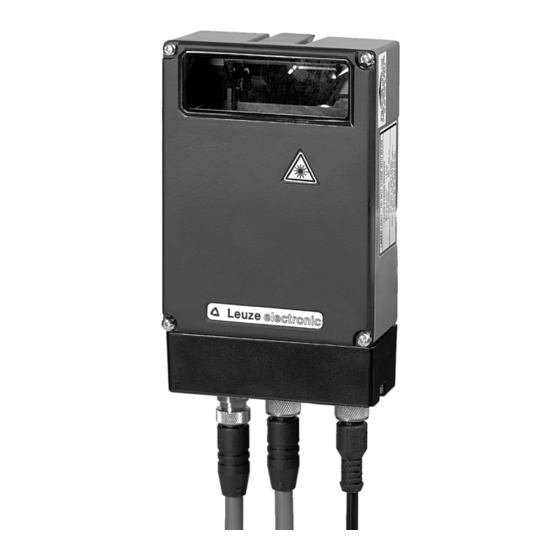
4 fastening threads M3 on the underside of the rear of the device unit Figure 3.1: BPS 37 device construction Application Anywhere systems are moved automatically, it is necessary to correctly determine their positions. This is achieved using various measurement techniques. In addition to mechan- ical measurement sensors, optical methods are particularly well suited for determining posi- tions as they operate without mechanical wear and slippage. -
Page 11: Function
• It is possible to exactly determine positions from distances of 10000 metres. Standalone operation The barcode positioning system BPS 37 is operated as a single "stand alone" device. The BPS features a 15-pin sub-D connector for the electrical connection of the supply voltage, the interface and the switching inputs. - Page 12 10 … 30 V DC 15 pin sub-D connector, socket ver- sion Figure 3.2: Connection BPS "Stand alone" With connection unit MA 4.7/MA4D.7 BPS 37 MA 4.7/MA 4D.7 Power Connection cable KB031-3000 Figure 3.3: BPS connection with connection unit MA 4.7 BPS 37...
-
Page 13: Technical Data
Environmental data Operation w/o optics heating 0°C … +40°C (BPS 37 S M 100) Operation with optics heating -30°C … +40°C (BPS 37 S M 100 H) Storage -20°C … +60°C Air humidity max. 90% rel. humidity, non-condensing Vibration IEC 68.2.6... -
Page 14: Led Indicators
LED indicators An internal LED indicates in the reading window whether or not the supply voltage is present. Dimensioned and Connection Drawings BPS 37 S M 100 / BPS 37 S M 100 H Rear view Plan view Figure 4.1: Dimensioned drawing BPS 37... - Page 15 Leuze electronic Technical Data Scanning curve BPS 37 BPS 37 Working range Reading distance in mm Figure 4.2: Scanning curve BPS 37 Leuze electronic BPS 37...
-
Page 16: Accessories / Order Designation
Accessories / Order Designation Accessories / Order Designation Accessories Notice! Products from Leuze electronic GmbH & Co KG can be ordered from any of the sales and service offices listed on the back page of this operating manual. Designation Part No. - Page 17 Leuze electronic Accessories / Order Designation Figure 5.1: Connection unit MA 4.7/MA 4D.7 / dimensioned drawing Leuze electronic BPS 37...
-
Page 18: Fastening Accessories
Leuze electronic Accessories / Order Designation 5.1.2 Fastening Accessories The mounting unit BT 56 is available for mounting the BPS 37. It is designed for rod instal- lation. Mounting device BT 56 Clamping jaws for mounting on the BPS Clamp profile for... -
Page 19: Installation
Leuze electronic sales office. © Observe the local regulations regarding disposal and packaging. Cleaning © Clean the glass window of the BPS 37 with a soft cloth before mounting. Remove all packaging remains, e.g. carton fibres or Styrofoam balls. Attention! Do not use aggressive cleaning agents such as thinner or acetone for cleaning the device and the barcode band. - Page 20 Mounting MA You can mount all connection units individually through the holes located on the mounting plate (see figure 5.1). Subsequently, connect the BPS 37 with the connection unit via the respective cable (see chapter 5.1.3). BPS 37 Leuze electronic...
-
Page 21: Device Arrangement
• the permitted working range is not exited Notice! On the BPS 37, the beam is not emitted perpendicular to the cover of the housing, but with an angle of 10° towards the top. This angle is intended to prevent total reflection on the bar- code band. - Page 22 Installation Minimum separation (see scanning curve) Figure 6.2: Beam outlet on the BPS 37 Mounting location © When selecting a mounting location, pay attention to • maintaining the required environmental conditions (humidity, temperature), • possible soiling of the reading window due to liquids, abrasion by boxes, or packaging material residues.
- Page 23 Leuze electronic Installation Application example Figure 6.3: Application example Leuze electronic BPS 37...
-
Page 24: Connection
Connection of the device and maintenance work while under voltage must only be carried out by a qualified electrician. The power supply unit for the generation of the supply voltage for the BPS 37 and the re- spective connection units must have a secure electrical insulation through double insulation and safety transformers according to DIN VDE 0551 (IEC 742). -
Page 25: Connection Ssi Interface
TXD/Serv TXD signal, service interface RS 232 Pin 13 Reserve Pin 14 Reserve Pin 15 Supply voltage 0VDC Table 6.1: Connection description BPS 37 6.3.2 Connection SSI interface Connection with MA MA 4.7/MA 4D.7 Control/drive SSI interface Terminals Connection 1... - Page 26 (EM pick-up) is discharged via the protective conductor connection. Connection of the protective conductor PE BPS 37 without cable KB 031-3000: connect PE to the housing of the BPS 37 or to the housing of the 15-pin SUB-D connector! BPS 37 with cable KB 031-3000:...
-
Page 27: Connection Of Switching Input And Output
Installation 6.3.3 Connection of switching input and output The BPS 37 is provided with a switching input and a switching output. The connection of the switching input and output is made according to figure 6.7: SWIN1 12 … 30 V DC max. -
Page 28: Wire Lengths And Shielding
The following maximum lengths for wires and the type of shielding to be used must be observed: Connecting Interface Max. wire length Shielding absolutely required, shield BPS 37 - Service RS 232 meshing absolutely required, flexible BPS 37/MA 4.7 - 1200m leads as twisted pairs and... -
Page 29: Commissioning
"Power On" test After connecting the operating voltage, the BPS 37 performs an automatic "Power On" func- tion test. Subsequently, the green LED lights up in the optics window of the BPS 37. Interface Proper function of the interface can be tested easiest in service operation using the service interface with the "BPSConfig"... -
Page 30: Parameter Sets
Current parameter set In this parameter set, the current settings for all device parameters are stored. When the BPS 37 is in operation, the parameter set is stored in the EEPROM of the BPS 37. The current set can be stored: •... -
Page 31: Operation
Connection You can connect a PC or terminal to the BPS 37 via the serial interface and configure the BPS 37 through this connection. For this, you need a crossed RS 232 connection cable (null modem cable) that provides the connections RxD, TxD and GND. -
Page 32: Communicating With The Device
© Place the installation CD in your CD drive. © Call up the installation file (e.g. Set-up.exe) The following window appears: Installation window Figure 9.1: Installation window © Confirm the following licence agreement and select the installation path in the following window: BPS 37 Leuze electronic... - Page 33 Leuze electronic Communicating with the Device Installation directory Figure 9.2: Installation directory © Confirm your entry with Continue, then follow the installation routine. For further information, please see the online help for the "BPSConfig" software. Leuze electronic BPS 37...
-
Page 34: Overview Of Commands And Parameters
Online commands can be used to send commands directly to the device for control and configuration. For this, the BPS 37 has to be connected to a host or service computer via the serial inter- face. The commands can be sent either via the host or the service interface. -
Page 35: General Parameter Structure
Settings can be made in this folder This folder contains all settings nec- for controlling how the BPS reacts essary for integrating the BPS to a to the application of a 24 V signal. control or drive system via an SSI interface. Leuze electronic BPS 37... -
Page 36: Maintenance
Usually, the barcode positioning system BPS 37 does not require any maintenance by the operator. Cleaning Should it become soiled, clean the glass window of the BPS 37 with a soft cloth. Notice! Do not use aggressive cleaning agents such as thinner or acetone for cleaning the device. - Page 38 Leuze electronic Leuze electronic GmbH + Co KG Postfach 11 11, D-73277 Owen/Teck Tel. (07021) 5730, Fax (07021) 573199 Sales and Service E-mail: info@leuze.de http://www.leuze.de Leuze electronic GmbH +Co KG Geschäftsstelle Frankfurt Ing. Franz Schmachtl KG Telefon (06181) 9177-0 IVO Leuze Vogtle Malanca s.r.l.
Need help?
Do you have a question about the BPS 37 and is the answer not in the manual?
Questions and answers