Table of Contents
Advertisement
Advertisement
Table of Contents

Subscribe to Our Youtube Channel
Related Manuals for Leuze electronic BCL348i


Summary of Contents for Leuze electronic BCL348i
- Page 1 Bar code reader T E C H N I C A L D E S C R I P T I O N...
- Page 2 Leuze electronic GmbH + Co. KG P.O. Box 1111, D- 73277 Owen Tel. +49(0) 7021/ 573-0, Fax +49(0)7021/ 573-199 info@leuze.de w.leuze.com Sales and Service Germany Sales Region North Sales Region South Sales Region East Phone 07021/573-306 Phone 07021/573-307 Phone 035027/629-106...
-
Page 3: Table Of Contents
Raster scanner (Raster Line)....................... 34 Fieldbus systems ......................35 4.5.1 PROFINET-IO..........................35 4.5.2 PROFINET-IO – star topology ..................... 37 4.5.3 PROFINET-IO – linear topology ....................38 Heater ..........................38 External parameter memory in the MS 348 / MK 348 ............ 38 Leuze electronic 348i... - Page 4 Ultra Low Density (L) - optics: BCL 348i OL 100 (H) ..............62 Installation and mounting ................63 Storage, transportation ....................63 Mounting the BCL 348i ....................64 6.2.1 Fastening with M4 x 5 screws ......................64 6.2.2 BT 56 mounting device ........................65 6.2.3 BT 59 mounting device ........................67 348i Leuze electronic...
- Page 5 Short description of the webConfig tool................ 95 9.4.1 Module overview in the Configuration menu................95 Commissioning and configuration..............97 10.1 General information on the PROFINET-IO implementation of the BCL 348i ....97 10.1.1 PROFINET-IO communication profile..................97 10.1.2 Conformance Classes ......................... 98 Leuze electronic 348i...
- Page 6 Module 39 – Number of digits ....................136 10.9.13 Module 40 – Code type (symbology)..................137 10.9.14 Module 41 – Code position in the swivel range................138 10.10 Data Processing......................139 10.10.1 Module 50 – Characteristics filter ....................139 10.10.2 Module 51 – Data filtering ......................141 348i Leuze electronic...
- Page 7 Overview of commands and parameters ..............180 11.1.1 General 'online' commands ....................... 181 11.1.2 ’Online’ commands for system control..................188 11.1.3 ’Online’ commands for configuration of switching inputs/outputs ..........189 11.1.4 ’Online’ commands for the parameter set operations ..............192 Leuze electronic 348i...
- Page 8 Repairs, servicing ......................207 14.3 Disassembling, packing, disposing ................207 Appendix ......................208 15.1 Declaration of Conformity..................... 208 15.2 ASCII character set ......................210 15.3 Bar code samples ......................214 15.3.1 Module 0.3 ..........................214 15.3.2 Module 0.5 ..........................215 348i Leuze electronic...
- Page 9 "Medium Density" reading field curve for line scanner with deflection mirror...... 57 Figure 5.14: "Medium Density" reading field curve for oscillating-mirror scanners ......... 58 Figure 5.15: Lateral "Medium Density" reading field curve for oscillating-mirror scanners ..... 58 Leuze electronic 348i...
- Page 10 Assignment of the device names to IP addresses............102 Figure 10.4: Assigning the device names to the configured IO devices ..........103 Figure 10.5: MAC address - IP address -individual device name ............104 Table 10.1: Device parameters......................109 348i Leuze electronic...
- Page 11 Example 2: Start-up delay > 0 and switch-on time > 0............153 Figure 10.8: Example 3: start-up delay > 0 switch-off signal prior to lapsing of the start-up delay ..154 Figure 10.9: Start-up delay in input mode ..................... 155 Figure 10.10: Switch-on time in input mode.................... 155 Leuze electronic 348i...
- Page 12 Declaration of conformity BCL 308 .................. 208 Figure 15.2: Connection hood / connector unit declaration of conformity..........209 Figure 15.3: Bar code sample labels (module 0.3) ................214 Figure 15.4: Bar code sample labels (module 0.5) ................215 348i Leuze electronic...
-
Page 13: General Information
You can find the Declaration of Conformity of the devices in the appendix of the manual on page 145. The manufacturer of the product, Leuze electronic GmbH & Co KG in D-73277 Owen, possesses a certified quality assurance system in accordance with ISO 9001. -
Page 14: Safety Notices
The bar code readers of the BCL 300i series are especially designed for the following areas of application: • Storage technology and materials handling, in particular for object identification on fast-moving transport systems • Pallet transport systems • Automobile sector • Omnidirectional reading 348i Leuze electronic... -
Page 15: Working Safely
CAUTION: Use of controls or adjustments or performance of procedures other than specified herein may result in hazardous light exposure. Leuze electronic 348i... -
Page 16: Figure 2.1: Attachment Of The Stick-On Labels With Warning Notices At The Bcl 348I
M12 MS 3xx connection hood 348i Line scanner and M12 MS 3xx connection hood Warning: laser aperture Name plate Figure 2.1: Attachment of the stick-on labels with warning notices at the BCL 348i 348i Leuze electronic... -
Page 17: Fast Commissioning / Operating Principle
• The reading distance lies in the middle area of the reading field. • The bar code labels are of good print quality and have good contrast ratios. • You do not use high-gloss labels. • There is no direct sunlight. Leuze electronic 348i... -
Page 18: Electrical Connectionbcl 348I
MS 348. In the integrated parameter memory, both the settings and the PROFINET name are saved and transmitted to a new device. Notice! In the case of PROFINET line topology, the network is interrupted when the BCL 348i removed from the MS 348. 348i Leuze electronic... -
Page 19: Figure 3.2: Bcl 348 I - Mk 348 Terminal Hood With Spring-Loaded Terminals
The shield is automatically contacted when the cable is lead into the metal screw fitting and fastened when the cord grip is closed. Then lead the individual wires into the terminals according to the diagram. Wire end sleeves are not necessary. Leuze electronic 348i... -
Page 20: Preparatory Profinet-Io Settings
PROFINET-IO Complete the necessary steps for commissioning a Siemens-S7 control as described below. Further information regarding the individual commissioning steps is provided in see chapter 10.4 "Configuration steps for a Siemens Simatic S7 control". 348i Leuze electronic... -
Page 21: Preparing The Control System
Configure the PROFINET-IO system with the HW Config of the SIMATIC Manager by inserting the BCL 348i into your project. Figure 3.4: Assignment of the device names to IP addresses Here, an IP address is assigned to a unique "device name". Leuze electronic 348i... -
Page 22: Transfer Of The Configuration To The Io Controller
Assignment of the IP addresses that were configured in the HW Config to the IO devices • Establishment of a connection between the IO Controller and configured IO devices • Cyclical data exchange Notice! Participants that have not been "named" cannot be contacted yet at this point in time! 348i Leuze electronic... -
Page 23: Configuration Of The Device Name - Device Naming
Multiple BCL 348i can be distinguished by the MAC addresses displayed. The MAC address may be found on the name plate of the respective bar code scanner. Figure 3.5: Assigning the device names to the configured IO devices Leuze electronic 348i... -
Page 24: Check Device Name
GSD file. Activate the desired modules (at least module 10 and one of the modules 21 … 27). 348i Leuze electronic... -
Page 25: Starting The Device
- on Good read, successful reading green, briefly off - briefly red - on No read, reading not successful yellow continuous light Service mode flashes red Warning set red continuous light Error, device error Leuze electronic 348i... - Page 26 2/5 Interleaved code type is limited to 10 digits of code content. If a code is moved through the reading field, the code content is decoded and forwarded to the superior system (PLC/PC) via the PROFINET-IO. 348i Leuze electronic...
-
Page 27: Bar Code Reading
(PLC/PC) via the PROFINET-IO. Please check the incoming data of the bar code information there. Alternatively, you can use a switching input for read activation (switching signal of a photo- electric sensor or 24VDC switching signal). Leuze electronic 348i... -
Page 28: Device Description
The interfaces (RS 232, RS 485 and RS 422) integrated in the various device models and the fieldbus systems (PROFIBUS DP, PROFINET-IO and Ethernet) offer optimum connec- tion to the superior host system. Leuze electronic 348i... -
Page 29: Characteristics Of The Bar Code Readers Of The Bcl 300I Series
CRT decoder with code fragment technology: The proven code fragment technology (CRT) enables bar code readers of the BCL 300i series to read bar codes with a small bar height, as well as bar codes with a damaged or soiled print image. 348i Leuze electronic... -
Page 30: Figure 4.2: Possible Bar Code Orientation
The two freely configurable switching inputs/outputs SWIO1 and SWIO2 can be assigned various functions and control e.g. activation of the BCL 348i or external devices, such as a PLC. System, warning and error messages provide assistance in setup/troubleshooting during commissioning and read operation. Leuze electronic 348i... -
Page 31: Device Construction
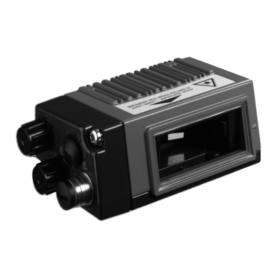
MK 3xx terminal hood MS 3xx hood with integrated connectors Display, LEDs and buttons Reading window Dovetail mounting and 4 mounting threads Line scanner with deflection mirror Figure 4.4: 348i device construction -line scanner with deflection mirror 348i Leuze electronic... -
Page 32: Figure 4.5: Bcl 348I Device Construction - Oscillating-Mirror Scanner
Device description Connection side for: MK 3xx terminal hood MS 3xx hood with integrated connectors Display, LEDs and buttons Dovetail mounting and 6 mounting threads Reading window Oscillating-mirror scanner Figure 4.5: 348i device construction - oscillating-mirror scanner Leuze electronic 348i... -
Page 33: Figure 4.6: Device Construction Ms 348 Hood With Integrated Connectors
MK 348 terminal hood Cable lead-throughs Terminal compartment Ethernet LEDs LINK / ACT Connection side with system plug for Mini-B type USB connection to service interface 348i Figure 4.7: Device construction MK 348 hood with integrated connectors 348i Leuze electronic... -
Page 34: Reading Techniques
• with bar codes having very short bar lengths. • when the ladder code is turned out of the vertical position (tilt angle). • when the reading distance is large. Figure 4.8: Deflection principle for the line scanner Leuze electronic 348i... -
Page 35: Line Scanner With Oscillating Mirror
• when the bars of the bar code are printed perpendicular to the conveying direction ('picket fence arrangement'). • when reading stationary objects. • when a large reading field (reading window) has to be covered. Figure 4.9: Deflection principle for the line scanner with oscillating mirror add-on 348i Leuze electronic... -
Page 36: Raster Scanner (Raster Line)
• when the bars of the bar code are perpendicular to the conveying direction ('picket fence arrangement') • with bar codes with low height displacement • with very glossy bar codes Figure 4.10: Deflection principle for the raster scanner Leuze electronic 348i... -
Page 37: Fieldbus Systems
• PROFINET-IO RT (Real Time) communication • Standard Fast Ethernet (100 Mbit/s) connections (M12 technology) • Integrated Ethernet switch/ 2 Ethernet ports • PROFINET-IO Conformance Class B (CC-B) • I&M support: I&M0 For further details, see Kapitel 10! 348i Leuze electronic... -
Page 38: Table 4.1
Base record I&M0 The BCL 348i supports further protocols and services for communication: • TCP / IP (Client / Server) • UDP • DCP • ARP • PING Further information on commissioning can be found in Kapitel 10. Leuze electronic 348i... -
Page 39: Profinet-Io - Star Topology
The PLC must communicate this device name to the participant during the "device naming". PC / PLC host interface 348i with MS348 hood with inte- grated connectors Other network participants 348i with MK348 terminal hood myBCL 348i_2 Figure 4.11: PROFINET-IO in a star topology 348i Leuze electronic... -
Page 40: Profinet-Io - Linear Topology
This eliminates the need to configure the exchanged device manually and, in particular, a new naming of the device – the control can immediately access the exchanged BCL 348i. Leuze electronic 348i... -
Page 41: Autoreflact
It is possible to store the reference codes via the webConfig tool, via online commands or PROFINET-IO. The BCL 348i can compare read bar codes with one and/or both reference codes and execute user-configurable functions depending on the comparison result. 348i Leuze electronic... -
Page 42: Autoconfig
PROFINET-IO are managed and configured exclusively by the PROFINET-IO Controller (PLC). Permanent changes must be carried out here! Detailed information on this topic can be found in Kapitel 10 "Inbetriebnahme und Konfigu- ration" auf Seite 97. Leuze electronic 348i... -
Page 43: Specifications
18 … 30VDC (Class 2, safety class III) Power consumption max. 3.7W Operating and display elements Display monochromatic graphical display, 128 x 32 pixel, with background lighting Keyboard 2 buttons LEDs 2 LEDs for power (PWR) and bus state (BUS), two-colored (red/green) Leuze electronic 348i... - Page 44 For UL applications, use is permitted exclusively in Class 2 circuits according to NEC (National Electric Code). The BCL 348i bar code readers are designed in accordance with safety class III for supply by PELV (protective extra-low voltage). 348i Leuze electronic...
-
Page 45: Oscillating-Mirror Scanner
Electrical data Power consumption max. 3.7W Mechanical data Weight 350g (without connection hood) 44 x 103 x 96mm (without connection hood) Dimensions (WxHxD) Table 5.2: Specifications of the BCL 348i deflection-mirror scanners without heating Leuze electronic 348i... -
Page 46: Heating Models Of The Bar Code Readers
To achieve an optimal heating effect, the BCL 348i should be mounted so that it is thermally isolated. Electrical connection The required core cross section of the connection cable for the voltage supply must be at least 0.75 mm². 348i Leuze electronic... -
Page 47: Line Scanner / Raster Scanner With Heater
Technical data same as for line scanner without heating with the following differences: Type 348i PROFINET-IO Type Oscillating-mirror scanner with heating Optical data Useful opening angle max. 60° Max. swivel angle ± 20°(adjustable) Table 5.4: Specifications of the BCL 348i oscillating-mirror scanners with heating Leuze electronic 348i... -
Page 48: Line Scanner / Raster Scanner With Deflection Mirror And Heating
-20°C … +70°C Table 5.4: Specifications of the BCL 348i oscillating-mirror scanners with heating 5.2.3 Line scanner / raster scanner with deflection mirror and heating Technical data same as for line scanner without heating with the following differences: 348i Leuze electronic... -
Page 49: Dimensioned Drawings
5.3.1 Dimensioned drawing of complete overview of the BCL 348i with MS 3xx / MK 3xx Figure 5.1: Dimensioned drawing of complete overview of the BCL 348i with MS 3xx / MK 3xx Leuze electronic 348i... -
Page 50: Dimensioned Drawing Of Line Scanner With / Without Heating
Specifications 5.3.2 Dimensioned drawing of line scanner with / without heating Optical axis Figure 5.2: Dimensioned drawing BCL 348i line scanner S…102 348i Leuze electronic... -
Page 51: Dimensioned Drawing Of Deflection Mirror Scanner With / Without Heating
Specifications 5.3.3 Dimensioned drawing of deflection mirror scanner with / without heating Optical axis Deflection angle of the laser beam: ± 30° Figure 5.3: Dimensioned drawing BCL 348i deflection mirror scanner S…100 Leuze electronic 348i... -
Page 52: Dimensioned Drawing Of Oscillating-Mirror Scanner With / Without Heating
Dimensioned drawing of oscillating-mirror scanner with / without heating Optical axis Swivel angle of the laser beam: ± 20° Deflection angle of the laser beam: ± 30° Figure 5.4: Dimensioned drawing BCL 348i oscillating mirror scanner O…100 348i Leuze electronic... -
Page 53: Dimensioned Drawing Of Ms 3Xx Hood With Integrated Connectors / Mk 3Xx Terminal Hood
To ensure protection class IP 65 is fulfilled, the screws of the connection hood are tightened with a tightening torque of 1.4Nm for connecting to the BCL. Figure 5.5: Dimensioned drawing of MS 3xx hood with integrated connectors / MK 3xx terminal hood Leuze electronic 348i... -
Page 54: Reading Field Curves / Optical Data
Therefore, above all, the module of a bar code is decisive for the size of the reading field. Notice! A rule of thumb: The smaller the module of the bar code is, the smaller the maximum reading distance and reading field width will be. 348i Leuze electronic... -
Page 55: Raster Scanner
8 scan lines which vary depending on the reading distance from the raster aperture. Distance [mm] starting at the zero position Front scanner Deflection mirror scanner Table 5.6: Raster line cover as a function of the distance Leuze electronic 348i... -
Page 56: Reading Field Curves
BCL 3xxi O…100… Figure 5.7: Zero position of the reading distance Reading conditions for the reading field curves 2/5 Interleaved Bar code type 1:2.5 Ratio class A ANSI specification > 75% Reading rate Table 5.7: Reading conditions 348i Leuze electronic... -
Page 57: High Density (N) - Optics: Bcl 348I S/R1 N 102 (H)
= 0,127 m = 0,15 m = 0,2 -100 Reading distance [mm] Figure 5.9: "High Density" reading field curve for line scanner with deflection mirror The reading field curve applies for the reading conditions stated in table 5.7. Leuze electronic 348i... -
Page 58: High Density (N) - Optics: Bcl 348I On 100 (H)
= 0,127 m = 0,15 m = 0,2 -100 Reading distance [mm] Figure 5.11: Lateral "High Density" reading field curve for oscillating-mirror scanners The reading field curves apply for the reading conditions stated in table 5.7. 348i Leuze electronic... -
Page 59: Medium Density (M) - Optics: Bcl 348I S/R1 M 102 (H)
= 0,3 m = 0,5 -100 -150 Reading distance [mm] Figure 5.13: "Medium Density" reading field curve for line scanner with deflection mirror The reading field curves apply for the reading conditions stated in table 5.7. Leuze electronic 348i... -
Page 60: Medium Density (M) - Optics: Bcl 348I Om 100 (H)
= 0,2 m = 0,3 m = 0,5 -100 -125 -150 Reading distance [mm] Figure 5.15: Lateral "Medium Density" reading field curve for oscillating-mirror scanners The reading field curves apply for the reading conditions stated in table 5.7. 348i Leuze electronic... -
Page 61: Low Density (F) - Optics: Bcl 348I S/R1 F 102 (H)
= 0,35 m = 0,5 -100 -150 -200 Reading distance [mm] Figure 5.17: "Low Density" reading field curve for line scanner with deflection mirror The reading field curves apply for the reading conditions stated in table 5.7. Leuze electronic 348i... -
Page 62: Low Density (F) - Optics: Bcl 348I Of 100 (H)
= 0,3 m = 0,35 m = 0,5 -100 -150 -200 Reading distance [mm] Figure 5.19: Lateral "Low Density" reading field curve for oscillating-mirror scanners The reading field curves apply for the reading conditions stated in table 5.7. 348i Leuze electronic... -
Page 63: Ultra Low Density (L) - Optics: Bcl 348I S/R1 L 102 (H)
= 0,8 -100 -150 -200 -250 -300 Reading distance [mm] Figure 5.21: "Ultra Low Density" reading field curve for line scanner with deflection mirror The reading field curves apply for the reading conditions stated in table 5.7. Leuze electronic 348i... -
Page 64: Ultra Low Density (L) - Optics: Bcl 348I Ol 100 (H)
= 0,5 m = 0,8 -100 -150 -200 -250 -300 Reading distance [mm] Figure 5.23: Lateral "Ultra Low Density" reading field curve for oscillating-mirror scanners The reading field curves apply for the reading conditions stated in table 5.7. 348i Leuze electronic... -
Page 65: Installation And Mounting
Device name plate BCL 348i Save the original packaging for later storage or shipping. Notice! All BCL 348i are delivered with a protective cover on the connection side which must be re- moved before attaching a connection hood. Leuze electronic 348i... -
Page 66: Mounting The Bcl 348I
Installation and mounting If you have any questions concerning your shipment, please contact your supplier or your local Leuze electronic sales office. Observe the applicable local regulations when disposing of the packaging materials. Mounting the BCL 348i The BCL... -
Page 67: Bt 56 Mounting Device
BCL 348i Clamp profile for fastening to round or oval pipes Ø 16 … 20mm All dimensions in mm A Rod holder, turnable 360° B Rods Ø 16 … 20mm Figure 6.3: BT 56 mounting device Leuze electronic 348i... -
Page 68: Figure 6.4: Mounting Example Of Bcl 348I With Bt 56
Installation and mounting Figure 6.4: Mounting example of BCL 348i with BT 56 348i Leuze electronic... -
Page 69: Bt 59 Mounting Device
For further information, see the notices in chapter 6.3! Please refer to chapter 5.4 for the permissible minimum and maximum distances between the BCL 348i and the labels to be read. Leuze electronic 348i... -
Page 70: Device Arrangement
• The reading distance lies in the middle area of the reading field. • The bar code labels are of good print quality and have good contrast ratios. • You do not use high-gloss labels. • There is no direct sunlight. 348i Leuze electronic... -
Page 71: Avoiding Total Reflection - Line Scanner
348i can be installed parallel to the bar code (rear housing wall). The BCL 348i with deflection mirror should be mounted Bar code parallel to the bar code. Zero position Figure 6.7: Total reflection – line scanner Leuze electronic 348i... -
Page 72: Avoiding Total Reflection - Oscillating-Mirror Scanner
• Possible soiling of the reading window due to liquids, abrasion by boxes, or packaging material residues. • Lowest possible chance of damage to the BCL 348i by mechanical collision or jammed parts. • Possible extraneous light (no direct sunlight or sunlight reflected by the bar code). 348i Leuze electronic... -
Page 73: Devices With Integrated Heating
(figure 6.9). β α γ γ Figure 6.9: Reading angle for the line scanner α Tilt β Angle of inclination (Pitch) γ Skew γ In order to avoid total reflection, the skew should be greater than 10°. Leuze electronic 348i... -
Page 74: Cleaning
Styrofoam balls. In doing so, avoid leaving finger- prints on the front cover of the BCL 348i. Attention! Do not use aggressive cleaning agents such as thinner or acetone for cleaning the device. 348i Leuze electronic... -
Page 75: Electrical Connection
Minimum tightening torque of the housing connection screws on the connection hood 1.4Nm! Location of the electrical connections Oscillating-mirror scanner Line scanner with deflection mirror Line scanner MK 348 MS 348 Terminals M12 connector Figure 7.1: Location of the electrical connections Leuze electronic 348i... -
Page 76: Safety Notices For The Electrical Connection
Protection class IP 65 is not fulfilled until connectors or cable lead-throughs are screwed on and caps are installed! Attention! To ensure protection class IP 65 is fulfilled, the screws of the connection hood are tightened with a tightening torque of 1.4Nm for connecting to the BCL. 348i Leuze electronic... -
Page 77: Electrical Connectionbcl 348I
Ethernet 0 LED Ethernet 1 LED (split, two-colored): (split, two-colored): ACT0 / LINK0 ACT1 / LINK1 Figure 7.2: 348i - MS 348 hood with integrated M12 connectors Notice! The shielding connection is done via the M12 connector housing. Leuze electronic 348i... -
Page 78: Mk 348 Terminal Hood With Spring-Loaded Terminals
The integrated parameter memory for simple exchange of the BCL 348i is located in the MK 348. In the integrated parameter memory, both the settings and the PROFINET name are saved and transmitted to a new device. 348i Leuze electronic... -
Page 79: Figure 7.4: Cable Fabrication For Mk 348 Terminal Hood
Then lead the individual wires into the terminals according to the diagram. Wire end sleeves are not necessary. Notice! See chapter 5.4 "Reading field curves / optical data" dimensioned drawing on page 52. Leuze electronic 348i... -
Page 80: Detailed Description Of The Connections
Connecting functional earth FE Ensure that the functional earth (FE) is connected correctly. Unimpaired operation is only guaranteed when the functional earth is connected properly. All electrical disturbances (EMC couplings) are discharged via the functional earth connection. 348i Leuze electronic... -
Page 81: Figure 7.1: Switching Input Connection Diagram Swio_1 And Swio_2
If, for example, the inverted sensor output is connected to pin 2, and pin 2 of the bar code reader is, at the same time, configured as an output (and not as an input), the switching output malfunctions. Attention! The maximum input current must not exceed 8mA! Leuze electronic 348i... -
Page 82: Figure 7.2: Switching Output Connection Diagram Swio_1 / Swio_2
60mA at +18 … +30VDC in normal operation! Notice! Both switching inputs/outputs SWIO_1 and SWIO_2 are configured by default in such a way that: • Switching input SWIO_1 activates the reading gate. • Switching output SWIO_2 switches by default on "No Read." 348i Leuze electronic... -
Page 83: Service - Usb Interface (Mini-B Type)
Use the Leuze specific USB service cable (See chapter 13 "Type overview and acces- sories") for the connection and use a service PC to configure. Notice! IP 65 is achieved only if the connectors and caps are screwed into place. Leuze electronic 348i... -
Page 84: Host / Bus In For Bcl 348 I
HOST / BUS IN cable assignments on RJ-45 Notice for connecting the PROFINET-IO interface! Ensure adequate shielding. The entire connection cable must be shielded and earthed. The RD+/RD- and TD+/TD- wires must be stranded in pairs. Use CAT 5 cable for the connection. 348i Leuze electronic... -
Page 85: Bus Out For The Bcl 348 I
Use CAT 5 cable for the connection. Notice! For the BCL 348i as standalone device or as the last participant in a linear topology, termi- nation on the BUS OUT socket is not mandatory! Leuze electronic 348i... -
Page 86: Profinet-Io Topologies
In addition to the classic "star topology", a "linear topology" is thus also possible. This makes wiring the network easy and inexpensive as participants are connected to one another in parallel. The maximum length of a segment (connection from one participant to the next) is limited to 100m. 348i Leuze electronic... -
Page 87: Profinet-Io Wiring
TD+ on the M12 connector with RD+ on the RJ-45 connector and TD- on the M12 connector with RD- on the RJ-45 connector, respectively, etc. Notice! Use the recommended connectors / sockets or the ready-made cables (See chapter 13 "Type overview and accessories"). Leuze electronic 348i... -
Page 88: Cable Lengths And Shielding
BCL to the absolutely required, PROFINET-IO RT 100m for last BCL shielded 100Base-TX Twisted Pair (min. Cat. 5) BCL – power not necessary supply unit not necessary Switching input not necessary Switching output Table 7.5: Cable lengths and shielding 348i Leuze electronic... -
Page 89: Display Elements And Display
- self test running - initialization running green continuous light Device ok - bar code reading possible - self test successfully finished - device monitoring active green, briefly off - on Good read, successful reading - bar code(s) successfully read 348i Leuze electronic... - Page 90 - network operation ok - connection and communication to IO Controller (PLC) established ("data exchange") flashes red Communication error Bus error - parameterization or configuration failed ("parameter failure") - IO error - no data exchange red continuous light Network error Leuze electronic 348i...
-
Page 91: Ms 348/Mk 348 Led Indicators
LED ACT0 / LINK0 (on the MS 348/MK 348/) green continuous light Ethernet connected (LINK) yellow flickering light Data communication (ACT) LED ACT1 / LINK1 (on the MS 348/MK 348/) green continuous light Ethernet connected (LINK) yellow flickering light Data communication (ACT) 348i Leuze electronic... -
Page 92: Display Bcl 348I
= Device name of the BCL 348i in PROFINET-IO • Adjustmode = alignment mode • Version = software and hardware version After the voltage is switched off/on, reading result is always displayed. The display is controlled via the two control buttons: Leuze electronic 348i... - Page 93 • 1st line: alignment mode display function • 2nd line: decoding quality in percent, e.g. 73% Version • 1st line: version display function SW: xxxxx HW: xxx • 2nd line: software and hardware version of the device 348i Leuze electronic...
-
Page 94: Leuze Webconfig Tool
The SERVICE USB interface of the BCL 348i is connected via the PC -side USB interface by means of a standard USB cable, with 1 type A connector and 1 Mini-B type connector. Mini-B Figure 9.1: Connecting the SERVICE USB interface 348i Leuze electronic... -
Page 95: Installing The Required Software
Upon successful installation of the USB driver, an icon with the name Leuze Web Config automatically appears on the desktop. Notice! If the installation failed, contact your network administrator: The settings of the firewall used may need to be adjusted. Leuze electronic 348i... -
Page 96: Starting The Webconfig Tool
Depending on firmware version, the start page may vary from that shown above. The individual parameters are – where useful – graphically displayed in order to better illustrate the meaning of the what are often perceived as abstract parameters. The result is an easy-to-use and practically-oriented user interface! 348i Leuze electronic... -
Page 97: Short Description Of The Webconfig Tool
The user interface of the webConfig tool is largely self-explanatory. 9.4.1 Module overview in the Configuration menu The adjustable parameters of the BCL 348i are clustered in modules in the Configuration menu. Figure 9.3: Module overview in the webConfig tool Leuze electronic 348i... - Page 98 "Load parameter from device" button after making the changes to update the display in the webConfig tool. This button appears in the upper left in the center window area in all submenus of the Configuration main menu. 348i Leuze electronic...
-
Page 99: Commissioning And Configuration
Acyclic data exchange, and also for the transfer of various information types such as: - Parameters for the configuration of the modules during the establishment of the communication - I&M data (Identification & Maintenance functions) - Reading diagnostic information - Reading I/O data - Writing device data Leuze electronic 348i... -
Page 100: Conformance Classes
M12 socket M12 socket (D-coded) (D-coded) Ethernet 0 Ethernet 1 Ethernet 0 LED Ethernet 1 LED (split, two-colored): (split, two-colored): ACT0 / LINK0 ACT1 / LINK1 Figure 10.1: BCL 348i - MS 348 hood with integrated M12 connectors 348i Leuze electronic... -
Page 101: Figure 10.2: Bcl 348I - Mk 348 Terminal Hood With Spring-Loaded Terminals
Connecting functional earth FE Ensure that the functional earth (FE) is connected correctly. Unimpaired operation is only guaranteed when the functional earth is connected properly. All electrical disturbances (EMC couplings) are discharged via the functional earth connec- tion. Leuze electronic 348i... -
Page 102: Starting The Device
In the following, the terms "GSD" or "GSD file" always refer to the GSDML-based format. The GSDML file can support an arbitrary number of languages in one file. Every GSDML file contains a version of the BCL 348i device model. This is also reflected in the file name. 348i Leuze electronic... - Page 103 PROFINET-IO, all parameters are set to default values. If these parameters are not changed by the user, the device functions with the default settings delivered by Leuze electronic. For the default settings of the BCL 348i, please refer to the following module descriptions.
-
Page 104: Step 3 - Hardware Configuration Of The S7 Plc: Configuration
• Assignment of the IP addresses that were configured in the HW Config to the IO devices • Establishment of a connection between the IO Controller and configured IO devices • Cyclical data exchange Notice! Participants that have not been "named" cannot be contacted yet at this point in time! 348i Leuze electronic... -
Page 105: Step 5 - Configuration Of The Device Name - Naming The Device
PROFINET-IO defines the "naming of the device" as the creation of a name-based relation- ship for a PROFINET-IO device. Assigning the device names to the configured IO devices Figure 10.4: Assigning the device names to the configured IO devices Leuze electronic 348i... -
Page 106: Figure 10.5: Mac Address - Ip Address -Individual Device Name
("device name"). Figure 10.5: MAC address - IP address -individual device name From now on, and when programming, only the unique "device name" (max. 255 characters) is used. 348i Leuze electronic... -
Page 107: Step 6 - Check Device Names
A simple test to determine whether the address assignment was successful is to enter the previously configured IP address in a ping command (e.g. "ping 192.168.60.101" in a command line window under Windows). Leuze electronic 348i... -
Page 108: Ethernet Host Communication
TCP server, also set the following values: • Port number for the communication of the BCL 348i with the TCP client The corresponding adjustment options can be found: Via webConfig: Configuration -> Communication -> Host communication 348i Leuze electronic... -
Page 109: Udp
All other parameters required for the reading task, such as setting the code type and number of digits, etc., are set using the engineering tool of the PLC with the aid of the various avail- able modules (see chapter 10.5). Leuze electronic 348i... -
Page 110: Commissioning Via The Profinet-Io
IO Controller (master). Before this is evaluated and the respective parameter values are set, all PROFINET-IO parameters are reset to default values. This ensures that the parameters of modules that are not selected are set to the default values. 348i Leuze electronic... -
Page 111: Permanently Defined Parameters / Device Parameters
Decodable number of digits in the Digits 5 UNSIGNED8 0 … 63 enumeration mode. Reading Min. reading reliability to be achieved in order UNSIGNED8 1 … 100 reliability to output a read code. Table 10.1: Device parameters Leuze electronic 348i... - Page 112 16.6 4: MOD10 Weight 4_9 5: MOD11 Cont 6: MOD43 7: MOD16 Check digit output Check digit 0: Standard Turns the check digit output on or off. 16.7 output 2 1: Not standard Table 10.1: Device parameters 348i Leuze electronic...
- Page 113 24.6 4: MOD10 Weight 4_9 5: MOD11 Cont 6: MOD43 7: MOD16 Check digit output Check digit 0: Standard Turns the check digit output on or off. 24.7 output 3 1: Not standard Table 10.1: Device parameters Leuze electronic 348i...
- Page 114 For a code table entry x, the two code lengths 10 and 12 are to be enabled. For this purpose, the following number of digit entries are necessary: Number of digits mode x = 0 (enumeration) Number of digits x.1 = 10 Number of digits x.2 = 12 348i Leuze electronic...
-
Page 115: Overview Of The Project Modules
(e.g., the decoding result modules 20-41). It is important to maintain the consistency of these data. The BCL 348i offers 34 different modules. Each of these modules may only be selected once; otherwise, the BCL 348i ignores the configuration. Leuze electronic 348i... -
Page 116: Table 10.2
Number of digits Number of digits in the bar code 1039 Code type Bar code type 1040 Code position in the swivel range of an Code position in the swivel range 1041 oscillating mirror device Table 10.2: Module overview 348i Leuze electronic... -
Page 117: Table 10.2
The number of parameter bytes does not include the constant module number, which is always transmitted in addition. Notice! For the standard case, at least module 10 (activation) and one of modules 21 … 27 (decoding result 1 … 7) should be integrated. Leuze electronic 348i... -
Page 118: Decoder Modules
0 … 63 mode. Decodable number of Digits 4 digits in the enumeration UNSIGNED8 0 … 63 mode. Decodable number of Digits 5 digits in the enumeration UNSIGNED8 0 … 63 mode. Table 10.3: Parameters for modules 1-4 348i Leuze electronic... - Page 119 Table 10.3: Parameters for modules 1-4 Cf. in Permanently defined parameters / device parameters section 10.5.2 the notice on number of digits. Parameter length 8 bytes Input data None Output data None Leuze electronic 348i...
-
Page 120: Module 5 - Code Type Features (Symbology)
BitArea and ASCII conversion used for Code 39. method) 2: ASCII (This con- version method uses the entire ASCII character set) Table 10.4: Parameters for module 5 Parameter length 6 byte Input data None Output data None 348i Leuze electronic... -
Page 121: Module 7 - Code Fragment Technology
This parameter should be set if the AutoControl function is activated (see chapter 10.16.3 "Module 92 – AutoControl"). If the parameter is not set, the bar code is immediately detected and processed further as soon as all necessary bar code elements are available. Leuze electronic 348i... -
Page 122: Control Modules
ACK). master Deletes decoding results that may have been stored Data reset 0 -> 1: Data reset and resets the input data of all modules. Free Free Table 10.7: Output data for module 10 348i Leuze electronic... - Page 123 Deletion of the input data areas of all modules. Exception: The input data of module 60 - device status (see chapter 10.12.1) is not deleted. For the status byte of decoding result modules 20 … 27 (see chapter 10.9.2), the two toggle bytes and the reading gate status remain unchanged. Leuze electronic 348i...
-
Page 124: Module 11 - Reading Gate Control
4: Reference code compari- son, i.e., the reading gate is terminated if a positive refer- ence code comparison has taken place. Table 10.8: Parameters for module 11 348i Leuze electronic... -
Page 125: Table 10.8
See "Identifier" on page 142, modules 52-54 "Identifier filter string" See Module 83 – Reference code comparison pattern 1 and Module 84 – Reference code comparison pattern 2 Parameter length 6 byte Input data None Output data None Leuze electronic 348i... -
Page 126: Module 12 - Multi-Label
If the number of decoded bar codes is within the set limits, no additional "No Reads" are output. Notice! When using this module, the ACK mode should be activated (see Module 10 – Activations, "Mode" parameter). Otherwise there is a risk of losing decoding results if the control is not fast enough. 348i Leuze electronic... -
Page 127: Module 13 - Fragmented Read Result
Fragment length, always corresponds to the configured Fragment size UNSIGNED8 0 … 28 fragment length, except for the last fragment. Table 10.12: Input data for module 13 Input data length 2 byte consistent Output data None Leuze electronic 348i... -
Page 128: Module 14 - Interlinked Read Result
1 byte Input data None Output data None Notice! An interlinked read result also requires Module 12 – Multi-label. In this mode, the additional information transmitted in modules 31ff relates to the last decoding result in the chain. 348i Leuze electronic... -
Page 129: Result Format
This signal represents the internal for acknowl- acknowledgement state of the control. edgement from the IO Controller Table 10.14: Input data for module 20 Attention: This does not necessarily correspond to the state at the time the bar code is scanned. Leuze electronic 348i... - Page 130 • New result • Result state All others remain unchanged. Data reset behavior: Upon data reset (see Module 10 – Activations), the input data is deleted, except for the reading gate status and the two toggle bits. 348i Leuze electronic...
-
Page 131: Modules 21-27 - Decoding Result
Bar code information with a Data 0-FFh length of consistently 28 bytes. UNSIGNED8 Table 10.15: Input data for modules 21 … 27 Attention: This does not necessarily correspond to the state at the time the bar code is scanned Leuze electronic 348i... - Page 132 This shortening is either from the left or the right depending on the setting in Module 30 – Data formatting. Shortening is indicated by the passed bar code data length. 348i Leuze electronic...
-
Page 133: Module 30 - Data Formatting
The "decoding result at reading gate start" parameter is only taken into account if the "Without ACK" mode is set (cf. "Module 10 – Activations" on page 120). Notice! The text for erroneous readings does not permit the use of ASCII characters that cannot be displayed (<0x20h). Leuze electronic 348i... -
Page 134: Module 31 - Reading Gate Number
0 … 1 UNSIGNED16 0 … 65535 number incremented continuously. At 65535, an overflow occurs and the counter starts afresh from 0. Table 10.17: Input data for module 31 Input data length 2 byte consistent Output data None 348i Leuze electronic... -
Page 135: Module 32 - Reading Gate Time
1/10 Code position 0 … 1 SIGNED16 ±450 ized to the zero position (middle posi- degree tion). Specified in 1/10 degrees. Table 10.19: Input data for module 33 Input data length 2 byte consistent Output data None Leuze electronic 348i... -
Page 136: Module 34 - Reading Reliability (Equal Scans)
Bar code length 0 … 1 UNSIGNED16 1 … 900 the code position specified in degree module 35 in 1/10 degrees. Table 10.21: Input data for module 35 Input data length 2 byte consistent Output data None 348i Leuze electronic... -
Page 137: Module 36 - Scans With Information
Addr. Data type Value range Init Unit value Decoding quality of the Decoding quality UNSIGNED8 0 … 100 transmitted bar code. Table 10.23: Input data for module 37 Input data length 1 byte consistent Output data None Leuze electronic 348i... -
Page 138: Module 38 - Code Direction
Data type Value range Init Unit value Number of digits of the transmit- Number of digits UNSIGNED8 0 … 48 ted bar code Table 10.25: Input data for module 39 Input data length 1 byte Output data None 348i Leuze electronic... -
Page 139: Module 40 - Code Type (Symbology)
10: EAN Addendum transmitted bar UNSIGNED8 (symbology) code 11: Codabar 12: Code93 13: GS1 DataBar Omnidirectional 14: GS1 DataBar Limited 15: GS1 DataBar Expanded Table 10.26: Input data for module 40 Input data length 1 byte Output data None Leuze electronic 348i... -
Page 140: Module 41 - Code Position In The Swivel Range
The position is nor- 0 … 1 SIGNED16 -200 … +200 1/10° swivel range malized to the zero position (middle position). Specified in 1/10 degrees. Table 10.27: Input data for module 41 Input data length 2 bytes Output data None 348i Leuze electronic... -
Page 141: Data Processing
2 … 3 UNSIGNED16 In this case, a +/- degree position bandwidth in degrees must be specified, within which the same bar code is permitted to be in the scanning beam. Table 10.28: Parameters for module 50 Leuze electronic 348i... -
Page 142: Table 10.28
Parameter length 8 byte Input data None Output data None All comparison criteria are AND linked; this means all active comparisons must be fulfilled before the just-decoded bar code can be identified as already decoded and then deleted. 348i Leuze electronic... -
Page 143: Module 51 - Data Filtering
Also permitted are '*' as placeholders for a character sequence of arbitrary length, and an 'x' if the character at the respective position is to be deleted. Notice! ASCII characters that cannot be displayed (<0x20h) must not be used. Leuze electronic 348i... -
Page 144: Identifier
1 … 5 bytes of Identifier 4 See identifier 1. 5 characters ASCII characters null terminated STRING 1 … 5 bytes of Identifier 5 See identifier 1. 5 characters ASCII characters null terminated Table 10.30: Parameters for module 52 348i Leuze electronic... -
Page 145: Module 53 - Segmentation Via Fixed Positions
10.11.2 Module 53 – Segmentation via fixed positions PROFINET-IO module identifier Module-ID 1053 Submodule-ID Description The module activates the segmentation via fixed positions. The parameters specify the iden- tifiers to be searched for, the output mode, and the positions. Leuze electronic 348i... -
Page 146: Table 10.31
3rd UNSIGNED8 0 … 127 The first character in the bar code has identifier position 1. If the parameter is = 0, it is deactivated. Table 10.31: Parameters for module 53 348i Leuze electronic... -
Page 147: Table 10.31
An identifier with less than 5 characters must be null terminated. However, if the identifier string consists of exactly 5 characters, it does not have to be null terminated. Notice! ASCII characters that cannot be displayed (<0x20h) must not be used in the identifier strings. Leuze electronic 348i... -
Page 148: Module 54 - Segmentation According To Identifier And Separator
Delimiter in the value that follows its identifier directly identifier/sepa- UNSIGNED8 0 … 127 after the identifier length. After the rator algorithm separator, the next identifier starts. Table 10.32: Parameters for module 54 Parameter length 29 byte 348i Leuze electronic... - Page 149 An identifier with less than 5 characters must be null terminated. However, if the identifier string consists of exactly 5 characters, it does not have to be null terminated. Notice! ASCII characters that cannot be displayed (<0x20h) must not be used in the identifier strings. Leuze electronic 348i...
-
Page 150: Module 55 - String Handling Parameters
UNSIGNED8 32 … 126 ‘x‘ character comparison. This permits certain areas to be deleted). Table 10.33: Parameters for module 55 Parameter length 3 byte Input data None Output data None 348i Leuze electronic... -
Page 151: Device Functions
Analogous to command H, activation of this bit triggers a restart of all electronics, incl. a restart of the PROFINET-IO stack. Output data length 1 byte Notice! When resetting the data (see Module 10 – Activations), the input data of this module is not deleted. Leuze electronic 348i... -
Page 152: Module 61 - Laser Control
1/10° increments 2 … 3 UNSIGNED16 -450 … +450 +450 1/10° position within the visible range of the laser. Table 10.36: Parameters for module 61 Parameter length 4 byte Input data None Output data None 348i Leuze electronic... -
Page 153: Module 63 - Alignment
Signal activates and deactivates 0 -> 1: On the alignment mode for optimum Alignment mode alignment of the BCL 348i with 1 -> 0: Off the bar code. Table 10.38: Output data for module 63 Output data length 1 byte Leuze electronic 348i... -
Page 154: Module 64 - Oscillating Mirror
-200 … +200 -200 1/10° the swivel range. Oscillation Common value for forward and UNSIGNED8 15 … 116 °/s frequency backward motion ´. Table 10.39: Parameters for module 64 Parameter length 6 byte Input data None Output data None 348i Leuze electronic... -
Page 155: Switching Inputs / Outputs Swio 1
Figure 10.7: Example 2: Start-up delay > 0 and switch-on time > 0 In example 2, the activation duration of the output is only dependent on the selected switch- on time; the switch-off signal has no effect. Leuze electronic 348i... -
Page 156: Figure 10.8: Example 3: Start-Up Delay > 0 Switch-Off Signal Prior To Lapsing Of The Start-Up Delay
The standard switch-off function at reading gate start is rather unsuited for this module since it causes the event counter to be reset on each reading gate start. Suitable as switch- off function for this example is the valid read result function; otherwise, all switch-off func- tions are deactivated. 348i Leuze electronic... -
Page 157: Parameters For Operating As An Input
This parameter specifies the min. activation duration for the selected input function in ms. The actual activation duration is calculated from the switch-on time as well as the switch-off delay. Input signal Output signal Switch-on time Start-up delay td_on Switch-off delay td_off Figure 10.10: Switch-on time in input mode Leuze electronic 348i... -
Page 158: Switch-On And Switch-Off Functions For Operation As An Output
Device in standby mode Motor and laser inactive. No device error An error was detected. Device error Device is in an error state. Positive reference code comparison 2 Negative reference code comparison 2 24 Table 10.40: Switch-on/switch-off functions 348i Leuze electronic... -
Page 159: Input Functions For Operation As An Input
This parameter specifies an event switch-off Switch-off which can reset the switching output. UNSIGNED8 function 2 Switch-off function 1 and switch-off functions" on function 2 are OR linked. page 156 Table 10.42: Parameters for module 70 – Input/Output 1 Leuze electronic 348i... - Page 160 The DC bias level also defines whether the output is low-active (0) or high-active (1). Switching on an I/O configured as an output means switching to the active state; switching off, on the other hand, results in switching to the inactive or idle state. 348i Leuze electronic...
-
Page 161: Module 71 - Switching Input/Output Swio2
(once) or also in the 1: SWOUT UNSIGNED8 (Event event of greater or equal to switches Counter) (multiple times) after the com- several parative value is reached. times Table 10.43: Parameters for module 71 – Input/Output 2 Leuze electronic 348i... -
Page 162: Parameters For Module 70 - Input/Output 1
The DC bias level also defines whether the output is low-active (0) or high-active (1). Switching on an I/O configured as an output means switching to the active state; switching off, on the other hand, results in switching to the inactive or idle state. 348i Leuze electronic... -
Page 163: Module 74 - Swio Status And Control
(Event Counter) exceeded The bit is reset to the init. value by resetting the event counter. again Table 10.44: Input data for module 74 Input/output status and control Input data length 2 bytes Leuze electronic 348i... -
Page 164: Table 10.45
[AF] for Counter switching output 2 back to 1 -> 0: No function Switching output 2 zero. Reserved Byte Table 10.45: Output data for module 74 Input/output status and control Output data length 2 bytes 348i Leuze electronic... -
Page 165: Data Output
See sorting criterion 1 criterion 3 to which sorting takes place. Sort Specifies the See sorting direction 1 direction 3 sorting direction. Table 10.46: Parameters for module 80 Parameter length 3 byte Input data None Output data None Leuze electronic 348i... -
Page 166: Reference Code Comparison
7: RC1 less than or equal to bar code less than or equal to 8: Bar code less than RC1 or bar code greater than RC2 Table 10.47: Parameters for module 81 – Reference code comparison 348i Leuze electronic... -
Page 167: Table 10.47
If this condi- tion is not satisfied, no positive refer- ence code compari- son is achieved. Table 10.47: Parameters for module 81 – Reference code comparison Parameter length 8 byte Input data None Output data None Leuze electronic 348i... -
Page 168: Parameters For Module 82 - Reference Code Comparison
7: RC1 less than or equal to bar code less than or equal to 8: Bar code less than RC1 or bar code greater than RC2 Table 10.48: Parameters for module 82 – Reference code comparison 348i Leuze electronic... - Page 169 If this condi- tion is not satisfied, no positive refer- ence code compari- son is achieved. Table 10.48: Parameters for module 82 – Reference code comparison Parameter length 8 byte Input data None Output data None Leuze electronic 348i...
-
Page 170: Parameter Module 83 - Reference Code Comparison Pattern
The defined comparison pattern affects both reference code comparators (Module 81 – Reference code comparator 1 and Module 82 – Reference code comparator 2). ASCII characters that cannot be displayed (<0x20h) must not be used in the comparison pattern. 348i Leuze electronic... -
Page 171: Parameter Module 84 - Reference Code Comparison Pattern
The defined comparison pattern affects both reference code comparators (Module 81 – Reference code comparator 1 and Module 82 – Reference code comparator 2). ASCII characters that cannot be displayed (<0x20h) must not be used in the comparison pattern. Leuze electronic 348i... -
Page 172: Special Functions
2: Unknown parison function 2. If it matches, the value 1 is output. Table 10.51: Input data for module 90 – Status and control Input data length 1 byte Output data None 348i Leuze electronic... -
Page 173: Module 91 - Autoreflact (Automatic Reflector Activation)
With a motor speed of UNSIGNED8 1 … 16 1000, 1 scan corresponds to a debounce time of 1ms. Table 10.52: Parameters for module 91 – AutoreflAct Parameter length 2 bytes Input data None Output data None Leuze electronic 348i... -
Page 174: Module 92 - Autocontrol
AutoControl function, note that the "Processing end at end of label" parameter in the CRT module should be set to allow for a better assessment of the bar code quality (see also "Module 7 – Code fragment technology" on page 119). 348i Leuze electronic... -
Page 175: Example Configuration: Indirect Activation Via The Plc
Include the following modules in your project: • Module 1010 – Activations • Module 1023 – Decoding result 12 bytes Parameter settings No parameters need to be set separately. The standard parameter set provides all required functions. Leuze electronic 348i... - Page 176 M 1023 byte 1 = data length The data length is entered in byte 1. M 1023 byte 2 = result The result hex 3F ("?" = no read) is transmitted. Internal processing of the data and Internal processing signaling of the non-reading. 348i Leuze electronic...
-
Page 177: Sample Configuration: Direct Activation Via The Switching Input
• Module 1023 – Decoding result 12 bytes Parameter settings of the "device parameters" Byte Description Init value Change value to: Code type 1 01: 2/5 Interleaved Digits 3 Table 10.55: Device parameters for example configuration 2 Leuze electronic 348i... - Page 178 0.2 = 1. M 1023 byte 1 = 1 The data length is entered in byte 1. M 1023 byte 2 = result The result hex 3F ("?" = no read) is transmitted. Internal processing Internal data processing. 348i Leuze electronic...
-
Page 179: Sample Configuration: Indirect Activation Via The Switching Input
Init value Change value to: [T2] Code type Code 39 0 (no code) [T3] Code type EAN8, EAN13 0 (no code) [T4] Code type Code 128 0 (no code) Table 10.56: Device parameters for example configuration 3 Leuze electronic 348i... -
Page 180: Module Parameters For Example Configuration 3
M 1023 byte 2 to 11 = result The decoding result is transmitted in the following 10 bytes. Internal processing Internal data processing. M 1018 bit 0.0 1 The activation bit 0.0 is reset to 0. 348i Leuze electronic... -
Page 181: Online Commands
’ ’ in the text of this manual. Most online commands are acknowledged by the BCL 348i and any requested data returned. For commands that are not acknowledged, command execution can be observed or monitored directly on the device. Leuze electronic 348i... -
Page 182: General 'Online' Commands
Software reset Command ’H’ Carries out a software reset. The device is restarted and reinitialized, Description leaving it in the same state as when the supply voltage is switched on. Parameter Acknowledgment ’S’ (start signal) 348i Leuze electronic... - Page 183 Code 93 ’13’ GS1 DataBar OMNIDIRECTIONAL ’14’ GS1 DataBar LIMITED ’15’ GS1 DataBar EXPANDED Number of digits of the read code Contents of the decoded label. A ↑ appears if the label was zzzzzz: not correctly read. Leuze electronic 348i...
- Page 184 Code 128, EAN 128 ’10’ EAN Addendum ’11’ Codabar ’12’ Code 93 ’13’ GS1 DataBar OMNIDIRECTIONAL ’14’ GS1 DataBar LIMITED ’15’ GS1 DataBar EXPANDED Contents of the decoded label. A ↑ appears if the label zzzzzz: was not correctly read. 348i Leuze electronic...
- Page 185 ’+’: Starts the adjustment mode. Parameter ’-’: Ends the adjustment mode. ’yyy_zzzzzz’ yyy: Reading quality in %. A high process availability is Acknowledgment ensured at read qualities > 75%. zzzzzz: Bar code information. Leuze electronic 348i...
- Page 186 Valid ’Rx’ command Acknowledgment ’1’ Invalid command ’2’ Insufficient memory for reference code ’3’ Reference code has not been saved ’4’ Reference code invalid Input = ’RS130678654331’ (Code 1 (1), RAM only (3), UPC (06), code Example information) 348i Leuze electronic...
- Page 187 After each reading via an ’RTy’ command, explicitly switch off the function again since failure to do so will interfere with other commands as well as prevent execution of a new ’RTx’ command. Leuze electronic 348i...
- Page 188 (variables) for the actual input. Defined reference code no. Acknowledgment ’1’ (Code 1) ’2’ (Code 2) Memory location for reference code ’0’ RAM+EEPROM, ’3’ RAM only Defined code type (see command ’CA’) Defined code information (1 … 63 characters) 348i Leuze electronic...
-
Page 189: Online' Commands For System Control
The command deactivates decoding. This command can be used to deactivate the reading gate. Following deactivation, the read result is Description output. Because the reading gate was manually deactivated and, thus, no GoodRead criterion was met, a NoRead is output. Parameter Acknowledgment None Leuze electronic 348i... -
Page 190: Online' Commands For Configuration Of Switching Inputs/Outputs
(e.g., inverted logic and a state of High corresponds to a voltage of 0V at the switching output). Parameter ’OA?’ ’OA S1=<a>;S2=<a>’ <a> State of the switching outputs ’0’ Acknowledgment ’1’ High ’I’ Configuration as switching input ’P’ Passive configuration 348i Leuze electronic... - Page 191 The logic state is output, i.e., an inverted logic is taken into account (e.g., inverted logic and a state of High corresponds to a voltage of 0V at the switching output). ’OD<a>’ Parameter <a> Selected switching output [1, 2], unit (dimensionless) Acknowledgment None Leuze electronic 348i...
- Page 192 ’OF [S1=<a>][;S2=<a>]’ <a> Function of the switching input/ output, unit [dimensionless]’ Parameter ’I Switching input ’O’ Switching output ’P’ Passive ’OF=<bb>’ <bb> Status acknowledgment ’00’ Acknowledgment ’01’ Syntax error ’02’ Parameter error ’03’ Other error 348i Leuze electronic...
-
Page 193: Online' Commands For The Parameter Set Operations
Copying the default parameters to the permanent memory and to the main memory ’PS=<aa>’ <aa> Status acknowledgment, unit [dimensionless] ’00’ ’01’ Syntax error Acknowledgment ’02’ Impermissible command length ’03’ Reserved ’04’ Reserved ’05’ Reserved ’06’ Impermissible combination, source type - target type Leuze electronic 348i... - Page 194 <Address> Relative address of the data within the data set ’aaaa’ Four-digit, unit [dimensionless] <Data length> Length of the parameter data to be transferred ’bbbb’ Four-digit, unit [length in bytes] <BCC> Check sum calculated as specified under BCC type 348i Leuze electronic...
- Page 195 ’05’ Impermissible number of data requested ’06’ Requested data does not (any longer) fit in the transmis- sion buffer ’07’ Impermissible address value ’08’ Read access after end of data set ’09’ Impermissible QPF data set type Leuze electronic 348i...
- Page 196 Relative address of the data within the data set ’aaaa’ Four-digit, unit [dimensionless] <P.value> Parameter value of the -bb- parameter stored at this address. The parameter set data is converted from HEX format to a 2-byte-ASCII format for transfer. 348i Leuze electronic...
- Page 197 Online commands Command ’PD’ ’PS=<aa>’ <aa> Status acknowledgment, unit [dimensionless] ’0’ No difference Acknowledgment ’1’ Syntax error negative ’2’ Impermissible command length ’6’ Impermissible combination, parameter set 1 and parameter set 2 ’8’ Invalid parameter set Leuze electronic 348i...
- Page 198 Four-digit, unit [dimensionless] <P.value> Parameter value of the -bb- parameter stored at this address. The parameter set data is converted from HEX format to a 2-byte-ASCII format for transfer. <BCC> Check sum calculated as specified under BCC type 348i Leuze electronic...
- Page 199 Impermissible command length ’03’ Impermissible value for checksum type Acknowledgment ’04’ Invalid check sum received ’05’ Impermissible data length ’06’ Invalid data (parameter limits violated) ’07’ Invalid start address ’08’ Invalid parameter set ’09’ Invalid parameter set type Leuze electronic 348i...
-
Page 200: Diagnostics And Troubleshooting
• Communication error on the PROFI- Check interface NET-IO: No communication to Check wiring Red, continuous light IO Controller established ("no data Cannot be corrected by resetting exchange") Send device to customer service Table 12.1: General causes of errors 348i Leuze electronic... -
Page 201: Interface Errors
Customer data (please complete) Device type: Company: Contact partner / department: Phone (direct): Fax: Street / No: ZIP code/City: Country: Leuze Service fax number: +49 7021 573 - 199 Leuze electronic 348i... -
Page 202: Type Overview And Accessories
Scanning princi- Line scanner (raster) Oscillating-mirror scanner Integrated fieldbus technology RS 232/RS 422 (standalone) RS 485 (multiNet Slave) Interface PROFIBUS DP ETHERNET TCP/IP, UDP PROFINET-IO RT BCL Bar code reader Table 13.1: Part number code BCL 348i 348i Leuze electronic... -
Page 203: Type Overview Bcl 348I
O M 100 D H with M optics, display and heating 50116423 348i O F 100 D H with F optics, display and heating 50116417 348i O L 100 D H with L optics, display and heating 50116420 Leuze electronic 348i... -
Page 204: Connection Hood Accessories
Mounting devices for the BCL 348i 13.7 Reflector accessories for autoReflAct Type designation Description Part no. Reflective tape no. 4 / Reflective tape as reflector for autoReflAct operation 50106119 100 x 100 mm Table 13.6: Reflector for autoReflAct operation 348i Leuze electronic... -
Page 205: Accessory Ready-Made Cables For Voltage Supply
348i 13.9 Accessory ready-made cables for bus connection 13.9.1 General information • Cable KB ET… for connecting to PROFINET-IO via M12 connector • Standard cable available in lengths from 2 … 30m • Special cables on request. Leuze electronic 348i... -
Page 206: Contact Assignments M12 Profinet-Io Connection Cable Kb Et
-25°C … +60°C (when used with drag chains) Material cable sheath: PUR (green), wire insulation: PE foam, free of halogens, silicone and PVC Bending radius > 65mm, suitable for drag chains Bending cycles > 10 , perm. acceleration < 5m/s 348i Leuze electronic... -
Page 207: Order Codes M12 Profinet-Io Connection Cable Kb Et
KB ET - 20000 - SSA Cable length 20m 50106903 KB ET - 25000 - SSA Cable length 25m 50106904 KB ET - 30000 - SSA Cable length 30m 50106905 Table 13.9: Bus connection cable for the BCL 348i Leuze electronic 348i... -
Page 208: Maintenance
Contact your Leuze distributor or service organization should repairs be required. The addresses can be found on the inside of the cover and on the back. Notice! When sending devices to Leuze electronic for repair, please provide an accurate description of the error. 14.3... -
Page 209: Appendix
Appendix Appendix 15.1 Declaration of Conformity Figure 15.1: Declaration of conformity BCL 348i Leuze electronic 348i... - Page 210 Appendix Figure 15.2: Connection hood / connector unit declaration of conformity 348i Leuze electronic...
-
Page 211: Ascii Character Set
End of data transmission block CANCEL Invalid END OF MEDIUM End of medium SUBSTITUTE Substitution ESCAPE Escape FILE SEPARATOR File separator GROUP SEPARATOR Group separator RECORD SEPARATOR Record separator UNIT SEPARATOR Unit separator SPACE Space EXCLAMATION POINT Exclamation point Leuze electronic 348i... - Page 212 Number Number Number Number Number COLON Colon SEMICOLON Semicolon < LESS THAN Less than EQUALS Equals > GREATER THAN Greater than QUESTION MARK Question mark COMMERCIAL AT Commercial AT Capital letter Capital letter Capital letter Capital letter 348i Leuze electronic...
- Page 213 REVERSE SLANT Reverse slant CLOSING BRACKET Closing bracket CIRCUMFLEX Circumflex UNDERSCORE Underscore ‘ GRAVE ACCENT Grave accent Lower case letter Lower case letter Lower case letter Lower case letter Lower case letter Lower case letter Lower case letter Leuze electronic 348i...
- Page 214 Lower case letter Lower case letter Lower case letter Lower case letter Lower case letter Lower case letter Lower case letter OPENING BRACE Opening brace VERTICAL LINE Vertical line CLOSING BRACE Closing brace TILDE Tilde DELETE (RUBOUT) Delete 348i Leuze electronic...
-
Page 215: Bar Code Sample Labels (Module 0.3)
Modul 0,3 Code type 10: EAN 13 Add-on SC 0 77889 abcde Code type 08: EAN 128 1 122334 455666 Modul 0,3 Code type 13: GS1 DataBar OMNIDIRECTIONAL leuze Figure 15.3: Bar code sample labels (module 0.3) Leuze electronic 348i... -
Page 216: Bar Code Sample Labels (Module 0.5)
Modul 0,5 A151617A 9876 5430 Code 128 Modul 0,5 Code type 10: EAN 13 Add-on SC 2 44332 fghij Code type 08: EAN 128 Modul 0,5 0 099887 766550 LEUZE Figure 15.4: Bar code sample labels (module 0.5) 348i Leuze electronic...
Need help?
Do you have a question about the BCL348i and is the answer not in the manual?
Questions and answers