Table of Contents
Advertisement
Quick Links
Advertisement
Table of Contents

Related Manuals for Leuze electronic BCL500i series


Summary of Contents for Leuze electronic BCL500i series
- Page 1 BCL504i Barcode reader T E C H N I C A L D E S C R I P T I O N...
- Page 2 Leuze electronic GmbH + Co. KG P.O. Box 1111, D- 73277 Owen / Teck Tel. +49(0) 7021/ 573-0, Fax +49(0)7021/ 573-199 info@leuze.de • www.leuze.com Sales and Service Germany Sales Region North Sales Region South Sales Region East Phone 07021/573-306 Phone 07021/573-307...
- Page 3 BCL 504 Device information - main menu The main menus BCL504i SF 102 Information about Leuze electronic • Device type GmbH & Co. KG • Software version SW: V 1.3.1 HW:1 • Hardware version SN: 0704-081894 001 • Serial number...
-
Page 4: Table Of Contents
Line scanner with oscillating mirror....................26 4.4.3 Omnidirectional reading....................... 27 Fieldbus systems ......................28 4.5.1 PROFIBUS DP ..........................28 Heater ..........................28 External parameter memory ................... 29 autoReflAct ........................30 Reference codes ......................30 4.10 autoConfig ........................31 Leuze electronic BCL 504... - Page 5 Ultra Low Density (L) Optics: BCL 504 i OL 100 H ...............62 5.7.11 Installation and mounting ................63 Storage, transportation ....................63 Mounting the BCL 504 i ....................64 6.2.1 Fastening with M4 x 6 screws ......................64 6.2.2 BT 56 mounting device ........................65 BCL 504 Leuze electronic...
- Page 6 Service menu..........................90 8.3.5 Actions menu ..........................91 Operation .......................... 93 Leuze webConfig tool..................95 Connecting the SERVICE USB interface................ 95 Installing the required software..................95 9.2.1 System requirements........................95 9.2.2 Installing the USB driver ......................96 Leuze electronic BCL 504...
- Page 7 10.7.1 Module 10 – Activations ......................119 10.7.2 Module 11 – Reading gate control .....................121 10.7.3 Module 12 – Multi-label ......................123 10.7.4 Module 13 – Fragmented read result ..................124 10.7.5 Module 14 – Interlinked read result ....................125 BCL 504 Leuze electronic...
- Page 8 Module 72 – Switching input/output SWIO3 ................162 10.12.8 Module 73 – Switching input/output SWIO4 ................164 10.12.9 Module 74 – SWIO status and control ..................166 10.13 Data output ........................169 10.13.1 Module 80 – Sorting........................169 Leuze electronic BCL 504...
- Page 9 Accessory ready-made cables for bus connection ............ 189 12.9.1 General information........................189 12.9.2 Contact assignment of KB PB… connection cable for PROFIBUS/multiNet plus ......189 12.9.3 Technical data of interface connection cable ................190 12.9.4 Order codes for interface connection cables................190 BCL 504 Leuze electronic...
- Page 10 13.3 Disassembling, packing, disposing ................191 Appendix ......................192 14.1 Declaration of conformity ..................... 192 14.2 ASCII character set ......................193 14.3 Barcode samples ......................197 14.3.1 Module 0.3 ..........................197 14.3.2 Module 0.5 ..........................198 Leuze electronic BCL 504...
- Page 11 Figure 5.21: Lateral "High Density" reading field curve for oscillating-mirror scanners with heating ..54 Figure 5.22: "Medium Density" reading field curve for line scanner with heating (without deflection mirror) ....................... 55 Figure 5.23: "Medium Density" reading field curve for line scanner with heating (with deflection mirror)... 56 BCL 504 Leuze electronic...
-
Page 12: Leuze Electronic Bcl 504 I
Table 10.3: Services for DPVM1 class 1 and slaves ................101 Table 10.4: Services for DPVM1 class 2 and slaves ................102 Figure 10.1: Connections of the BCL 504i ....................103 Table 10.5: "Common" Parameters......................108 Leuze electronic BCL 504... - Page 13 Figure 10.2: Example 1: Start-up delay > 0 and switch-on time = 0 ............153 Figure 10.3: Example 2: Start-up delay > 0 and switch-on time > 0 ............153 Figure 10.4: Example 3: Start-up delay >0 Switch-off signal prior to lapsing of the start-up delay... 154 BCL 504 Leuze electronic...
- Page 14 Figure 12.8: Cable structure of PROFIBUS/multiNet plus connection cable..........189 Table 12.9: Bus connection cables for the BCL 504i ................190 Figure 14.1: Barcode sample labels (module 0.3)..................197 Figure 14.2: Barcode sample labels (module 0.5)..................198 Leuze electronic BCL 504...
-
Page 15: General Information
You can find the Declaration of Conformity of the devices in the appendix of the manual on page 192. The manufacturer of the product, Leuze electronic GmbH & Co KG in D-73277 Owen/Teck, possesses a certified quality assurance system in accordance with ISO 9001. -
Page 16: Safety Notices
The barcode readers of the BCL 500 series are especially designed for the following areas of application: • Storage and conveying technologies, in particular for object identification on fast-mov- ing conveyor belts • Pallet transportation applications • Automobile sector • Omnidirectional reading Leuze electronic BCL 504... -
Page 17: Working Safely
CAUTION: Use of controls or adjustments or performance of procedures other than specified herein may result in hazardous light exposure. The use of optical instruments or devices in combination with the device increases the danger of eye damage! BCL 504 Leuze electronic... -
Page 18: Figure 2.1: Attachment Of The Stick-On Labels With Warning Notices At The Bcl 504I
BCL 504i, attach them in- stead in the immediate vicinity of the BCL 504i in such a way that it is not necessary to look into the laser beam when reading the notices! Leuze electronic BCL 504... -
Page 19: Fast Commissioning / Operating Principle
• The reading distance lies in the middle area of the reading field. • The barcode labels are of good print quality and have good contrast ratios. • You do not use high-gloss labels. • There is no direct sunlight. BCL 504 Leuze electronic... -
Page 20: Electrical Connectionbcl 504 I
Further information can be found in chapter "Parameter enabling" on page 93. As a first step, you need to set the device address of the BCL 504 Leuze electronic BCL 504... -
Page 21: Setting The Device Address On The Display
BUS address. An accidental, incorrect entry can be cor- <-|0123456789 save rected by selecting and then pressing <-| Standard ----- Unit Then use the buttons to select save and save the set PROFIBUS address by pressing BCL 504 Leuze electronic... -
Page 22: Bcl 504 I On The Profibus
Activate the desired modules (at least module 10 and one of the modules 21 … 27). Store the slave address for the BCL 504i in the PROFIBUSmanager. Ensure that the address is the same as the address configured in the device. You can find further information beginning on page 106. Leuze electronic BCL 504... -
Page 23: Barcode Reading
Alternatively, you can connect a photoelectric sensor or a 24 V DC switching signal to the SW IN/OUT socket for read activation. To do this, however, you must appropriately configure the switching input (see chapter 7.2.3 "SW IN/OUT – Switching input/switching output"). BCL 504 Leuze electronic... -
Page 24: Device Description
• Integrated fieldbus connectivity = -> Plug-and-Play fieldbus coupling and easy net- working • Numerous interface variants facilitate connection to the primary systems • RS 232, RS 422 as well as with integrated multiNet plus master Leuze electronic BCL 504... - Page 25 CRT decoder with code fragment technology: The proven code fragment technology (CRT) enables barcode readers of the BCL 500 series to read barcodes with a small bar height, as well as barcodes with a damaged or soiled print image. BCL 504 Leuze electronic...
-
Page 26: Figure 4.2: Possible Barcode Orientation
The four freely configurable switching inputs/outputs "SWIO 1 … SWIO 4" can be assigned various functions and control e.g. activation of the BCL 504 or external devices, such as a PLC. System, warning and error messages provide assistance in set-up/troubleshooting during commissioning and read operation. Leuze electronic BCL 504... -
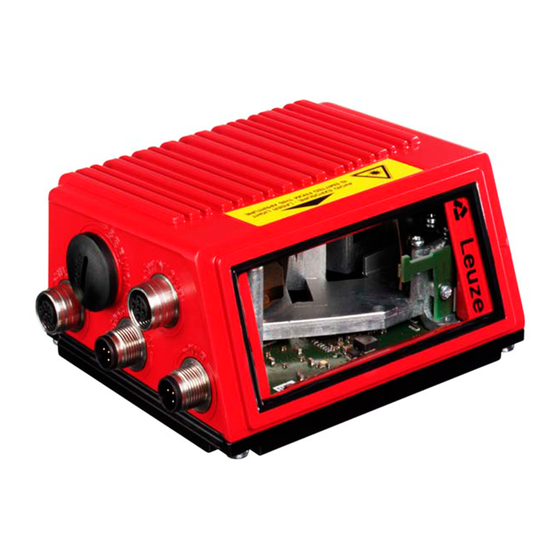
Page 27: Device Construction
Device description Device construction Reading window USB interface M12 connection technology Dovetail mounting and 4 mounting threads Display, LEDs and buttons Dovetail mounting and 2 mounting threads Figure 4.3: Device construction BCL 504 Leuze electronic... -
Page 28: Reading Techniques
• with barcodes having very short bar lengths. • when the ladder code is turned out of the vertical position (tilt angle). • when the scanning distance is large. Figure 4.4: Deflection principle for the line scanner Leuze electronic BCL 504... -
Page 29: Line Scanner With Oscillating Mirror
• when the barcode is turned out of the horizontal position. • when the scanning distance is large. • when a large reading field (reading window) has to be covered. Figure 4.5: Deflection principle for the line scanner with oscillating mirror add-on BCL 504 Leuze electronic... -
Page 30: Omnidirectional Reading
In order to read arbitrarily oriented barcodes on an object, at least 2 barcode readers are necessary. If the barcode is not printed over-square, i.e. bar length > code length, barcode readers with integrated code fragment technology are necessary. Figure 4.6: Principle arrangement for omnidirectional reading Leuze electronic BCL 504... -
Page 31: Fieldbus Systems
For low-temperature applications to min. -35°C (e.g. in cold storage), the barcode readers of the BCL 504 series can optionally be permanently fitted with a built-in heating and these barcode readers purchased as separate device models. BCL 504 Leuze electronic... -
Page 32: External Parameter Memory
USB connection on the BCL 504i after which the USB memory stick is plugged into the connection and the hood with integrated connectors closed with the cover in order to ensure protection class IP 65. Leuze electronic BCL 504... -
Page 33: Autoreflact
It is possible to store the reference codes by means of teach-in (display command), via the webConfig tool or via the PROFIBUS. The BCL 504 can compare read barcodes with one and/or both reference codes and execute user-configurable functions depending on the comparison result. BCL 504 Leuze electronic... -
Page 34: Autoconfig
BCL 504 Afterward, barcodes with the same code type and number of digits are recognised and decoded. Leuze electronic BCL 504... -
Page 35: Specifications
128 x 64 pixel, with background lighting Keyboard 4 buttons LEDs 2 LEDs for power (PWR) and bus state (BUS), two-coloured (red/green) Table 5.1: Specifications of the BCL 504 line scanners without heating BCL 504 Leuze electronic... - Page 36 For UL applications, use is permitted exclusively in Class 2 circuits according to NEC (Na- tional Electric Code). The BCL 504i barcode readers are designed in accordance with safety class III for supply by PELV (protective extra-low voltage with reliable disconnection). Leuze electronic BCL 504...
-
Page 37: Oscillating-Mirror Scanner
Max. optical adjustment range of ±10° (adjustable via display or software) the beam exit Electrical data Power consumption max. 11W Mechanical data Weight 1.4kg 84 x173 x147mm Dimensions (WxHxD) Table 5.3: Specifications of the BCL 504 deflection-mirror scanners without heating BCL 504 Leuze electronic... -
Page 38: Heating Models Of The Barcode Readers
22°C. Electrical connection The required core cross-section of the connection cable for the voltage supply must be at least 0.75 mm². Attention! The voltage supply must not be looped through from one device to the next. Leuze electronic BCL 504... -
Page 39: Line Scanner With Heating
Structure of the heating Housing heating and separate heating of the optics glass Warmup time Min. 30min at +24VDC and an ambient temperature of -35°C Table 5.5: Specifications of the BCL 504 oscillating-mirror scanners with heating BCL 504 Leuze electronic... -
Page 40: Line Scanner With Deflection Mirror And Heating
Wiring through of the voltage supply to multiple heating devices is not permissi- ble. Standard, M12 ready-made cable not usable (insufficient cable cross-section) Environmental data Operating temperature range -35°C … +40°C Storage temperature range -20°C … +70°C Table 5.6: Specifications of the BCL 504 deflection-mirror scanners with heating Leuze electronic BCL 504... -
Page 41: Dimensioned Drawings
Specifications Dimensioned drawings 5.3.1 Line scanner with / without heating A – Optical axis Figure 5.1: Dimensioned drawing BCL 504 line scanner S…102 BCL 504 Leuze electronic... -
Page 42: Deflection Mirror Scanner With / Without Heating
B – Optical adjustment range C – Opening angle The opening angle is reduced on devices with heating, see "Reading field curves for heating devices" on page 52. Figure 5.2: Dimensioned drawing BCL 504 deflection-mirror scanner S…100 Leuze electronic BCL 504... -
Page 43: Oscillating-Mirror Scanner With / Without Heating
C – Opening angle The optical swivel range and the opening angle are reduced on devices with heating, see "Reading field curves for heating devices" on page 52. Figure 5.3: Dimensioned drawing BCL 504 oscillating-mirror scanner O…100 BCL 504 Leuze electronic... -
Page 44: Type Overview Bcl 504 I
Oscillating-mirror scanner 501 09897 BCL 504 SL 102 H Line scanner, beam exit at the front, with heating 501 09899 BCL 504 OL 100 H Oscillating-mirror scanner with heating 501 09900 Table 5.7: Type overview BCL 504 Leuze electronic BCL 504... -
Page 45: Reading Field Curves / Optical Data
Therefore, above all, the module of a barcode is decisive for the size of the reading field. Notice! A rule of thumb: The smaller the module of the barcode is, the smaller the maximum reading distance and reading field width will be. BCL 504 Leuze electronic... -
Page 46: Reading Field Curves
Distance acc. to reading field curves Figure 5.5: Zero position of the reading distance Reading conditions for the reading field curves 2/5 Interleaved Barcode type 1:2.5 Ratio class A ANSI specification > 75% Reading rate Table 5.8: Reading conditions Leuze electronic BCL 504... -
Page 47: High Density (N) Optics: Bcl 504 I Sn 100/102
= 0,5 -100 -200 -300 -400 -100 1000 Read distance [mm] Figure 5.6: "High Density" reading field curve for line scanner (with/without deflection mirror) The reading field curve applies for the reading conditions stated in table 5.8. BCL 504 Leuze electronic... -
Page 48: High Density (N) Optics: Bcl 504 I On 100
= 0,5 -100 -200 -300 -400 -100 1000 Read distance [mm] Figure 5.8: Lateral "High Density" reading field curve for oscillating-mirror scanners The reading field curves apply for the reading conditions stated in table 5.8. Leuze electronic BCL 504... -
Page 49: Medium Density (M) Optics: Bcl 504 I Sm 100/102
-100 -200 -300 -400 -100 1000 1100 Read distance [mm] Figure 5.9: "Medium Density" reading field curve for line scanner (with/without deflection mirror) The reading field curves apply for the reading conditions stated in table 5.8. BCL 504 Leuze electronic... -
Page 50: Medium Density (M) Optics: Bcl 504 I Om 100
= 1,0 -100 -200 -300 -400 -100 1000 1100 Read distance [mm] Figure 5.11: Lateral "Medium Density" reading field curve for oscillating-mirror scanners The reading field curves apply for the reading conditions stated in table 5.8. Leuze electronic BCL 504... -
Page 51: Low Density (F) Optics: Bcl 504 I Sf 100/102
900 1000 1100 1200 1300 1400 1500 1600 1700 Read distance [mm] Figure 5.12: "Low Density" reading field curve for line scanner (with/without deflection mirror) The reading field curves apply for the reading conditions stated in table 5.8. BCL 504 Leuze electronic... -
Page 52: Low Density (F) Optics: Bcl 504 I Of 100
900 1000 1100 1200 1300 1400 1500 1600 1700 -100 Read distance [mm] Figure 5.14: Lateral "Low Density" reading field curve for oscillating-mirror scanners The reading field curves apply for the reading conditions stated in table 5.8. Leuze electronic BCL 504... -
Page 53: Ultra Low Density (L) Optics: Bcl 504 I Sl 102
1600 1800 2000 2200 2400 2600 Read distance [mm] Figure 5.15: "Ultra Low Density" reading field curve for line scanner without deflection mirror The reading field curves apply for the reading conditions stated in table 5.8. BCL 504 Leuze electronic... -
Page 54: Ultra Low Density (L) Optics: Bcl 504 I Ol 100
1200 1400 1600 1800 2000 2200 2400 2600 Read distance [mm] Figure 5.17: Lateral "Ultra Low Density" reading field curve for oscillating-mirror scanners The reading field curves apply for the reading conditions stated in table 5.8. Leuze electronic BCL 504... -
Page 55: Reading Field Curves For Heating Devices
-200 -300 -400 -100 1000 Read distance [mm] Figure 5.18: "High Density" reading field curve for line scanner with heating (without deflection mirror) The reading field curve applies for the reading conditions stated in table 5.8. BCL 504 Leuze electronic... -
Page 56: High Density (N) Optics: Bcl 504 I Sn 100 H
-200 -300 -400 -100 1000 Read distance [mm] Figure 5.19: "High Density" reading field curve for line scanner with heating (with deflection mirror) The reading field curve applies for the reading conditions stated in table 5.8. Leuze electronic BCL 504... -
Page 57: High Density (N) Optics: Bcl 504 I On 100 H
= ±12˚ -100 -200 -300 -400 -100 1000 Read distance [mm] Figure 5.21: Lateral "High Density" reading field curve for oscillating-mirror scanners with heating The reading field curves apply for the reading conditions stated in table 5.8. BCL 504 Leuze electronic... -
Page 58: Medium Density (M) Optics: Bcl 504 I Sm 102 H
-300 -400 -100 1000 1100 Read distance [mm] Figure 5.22: "Medium Density" reading field curve for line scanner with heating (without deflection mirror) The reading field curves apply for the reading conditions stated in table 5.8. Leuze electronic BCL 504... -
Page 59: Medium Density (M) Optics: Bcl 504 I Sm 100 H
-300 -400 -100 1000 1100 Read distance [mm] Figure 5.23: "Medium Density" reading field curve for line scanner with heating (with deflection mirror) The reading field curves apply for the reading conditions stated in table 5.8. BCL 504 Leuze electronic... -
Page 60: Medium Density (M) Optics: Bcl 504 I Om 100 H
-100 -200 -300 -400 -100 1000 1100 Read distance [mm] Figure 5.25: Lateral "Medium Density" reading field curve for oscillating-mirror scanners with heating The reading field curves apply for the reading conditions stated in table 5.8. Leuze electronic BCL 504... -
Page 61: Low Density (F) Optics: Bcl 504 I Sf 102 H
900 1000 1100 1200 1300 1400 1500 1600 1700 Read distance [mm] Figure 5.26: "Low Density" reading field curve for line scanner with heating (without deflection mirror) The reading field curves apply for the reading conditions stated in table 5.8. BCL 504 Leuze electronic... -
Page 62: Low Density (F) Optics: Bcl 504 I Sf 100 H
900 1000 1100 1200 1300 1400 1500 1600 1700 Read distance [mm] Figure 5.27: "Low Density" reading field curve for line scanner with heating (with deflection mirror) The reading field curves apply for the reading conditions stated in table 5.8. Leuze electronic BCL 504... -
Page 63: Low Density (F) Optics: Bcl 504 I Of 100 H
900 1000 1100 1200 1300 1400 1500 1600 1700 -100 Read distance [mm] Figure 5.29: Lateral "Low Density" reading field curve for oscillating-mirror scanners with heating The reading field curves apply for the reading conditions stated in table 5.8. BCL 504 Leuze electronic... -
Page 64: Ultra Low Density (L) Optics: Bcl 504 I Sl 102 H
2000 2200 2400 2600 Read distance [mm] Figure 5.30: "Ultra Low Density" reading field curve for line scanner with heating (without deflection mirror) The reading field curves apply for the reading conditions stated in table 5.8. Leuze electronic BCL 504... -
Page 65: Ultra Low Density (L) Optics: Bcl 504 I Ol 100 H
1600 1800 2000 2200 2400 2600 Read distance [mm] Figure 5.32: Lateral "Ultra Low Density" reading field curve for oscillating-mirror scanners with heating The reading field curves apply for the reading conditions stated in table 5.8. BCL 504 Leuze electronic... -
Page 66: Installation And Mounting
Save the original packaging for later storage or shipping. If you have any questions concerning your shipment, please contact your supplier or your local Leuze electronic sales office. Observe the applicable local regulations when disposing of the packaging materials. Leuze electronic... -
Page 67: Mounting The Bcl 504 I
• Using two M4x6 screws on the rear of the device or using four M4x6 screws on the bottom of the device. • Using a BT 56 mounting device on the two fastening grooves. 6.2.1 Fastening with M4 x 6 screws Figure 6.2: Fastening options using M4x6 threaded holes BCL 504 Leuze electronic... -
Page 68: Bt 56 Mounting Device
BCL 504 Clamp profile for mounting to round or oval pipes Ø 16 … 20mm All dimensions in mm A Rod holder, turnable 360° B Rods Ø 16 … 20mm Figure 6.3:BT 56 mounting device Leuze electronic BCL 504... -
Page 69: Device Arrangement
• The display and control panel should be very visible and accessible. • For configuring and commissioning with the webConfig tool, the USB interface should be easily accessible. For specific information, please refer to chapter 4.4. BCL 504 Leuze electronic... -
Page 70: Avoiding Total Reflection - Line Scanner
This means that in order to be on the safe side and to avoid total reflection, the BCL 504 with oscillating/deflection mirror must be inclined upward or downward 20° … 30°! Leuze electronic BCL 504... -
Page 71: Mounting Location
• Mount in such a way that the device is protected from draughts and wind; mount addi- tional shields if necessary. Notice! When installing the BCL 504i in a protective housing, it must be ensured that the scanning beam can exit the protective housing without obstruction. BCL 504 Leuze electronic... -
Page 72: Maximum Permissible Read Angles Between Bcl 504 I And Barcode
Styrofoam balls. In doing so, avoid leaving fin- gerprints on the front cover of the BCL 504i. Attention! Do not use aggressive cleaning agents such as thinner or acetone for cleaning the device. Leuze electronic BCL 504... -
Page 73: Electrical Connection
III for supply by PELV (protective extra-low voltage with reliable disconnection). Notice! Protection class IP65 is achieved only if the connectors and caps are screwed into place! BCL 504 Leuze electronic... -
Page 74: Electrical Connection Of The Bcl 504 I
N.C. 3 N.C. B (P) SWIO_4 B (P) M12 socket M12 plug M12 plug (B-coded) (B-coded) (A-coded) Figure 7.2: Connections of the BCL 504 Described in detail in the following are the individual connections and pin assignments. Leuze electronic BCL 504... -
Page 75: Pwr - Voltage Supply And Switching Input/Outputs 3 And 4
After reconnecting to the PROFIBUS or after deactivat- ing parameter enabling, the parameter settings set by the PROFIBUS are again active! BCL 504 Leuze electronic... -
Page 76: Figure 7.1: Switching Input Connection Diagram Swio_3 And Swio_4
Switching output connection diagram SWIO_3 / SWIO_4 Attention! Each configured switching output is short-circuit proof! Do not load the respective switching output of the BCL 504i with more than 60mA at +10 … +30VDC in normal operation! Leuze electronic BCL 504... -
Page 77: Service - Usb Interface (Type A)
Use the Leuze-specific USB service cable (see chapter 12 "Type overview and acces- sories") for the connection and use a service PC to configure. Note! IP 65 is achieved only if the connectors and caps are screwed into place. BCL 504 Leuze electronic... -
Page 78: Sw In/Out - Switching Input/Switching Output
If, for example, the inverted sensor output is connected to pin 2, and pin 2 of the barcode reader is, at the same time, configured as an output (and not as an input), the switching output malfunctions. Attention! The maximum input current must not exceed 8mA! Leuze electronic BCL 504... -
Page 79: Host / Bus In For Bcl 504 I
Receive/transmit data A-line (N) N.C. Not used N.C. 3 N.C. B (P) Receive/transmit data B-line (P) Functional earth B (P) M12 plug Thread Functional earth (housing) (B-coded) Table 7.4: Pin assignment HOST / BUS IN BCL 504 BCL 504 Leuze electronic... -
Page 80: Bus Out For The Bcl 504 I
USB specifications Acc. to PNO speci- PROFIBUS PROFIBUS DP Acc. to PNO specifications fications BCL – power not necessary supply unit not necessary Switching input not necessary Switching output Table 7.6: Line lengths and shielding Leuze electronic BCL 504... -
Page 81: Display And Control Panel
Switching input or switching output 4 active (function dependent on set configura- tion). Default: Switching output with the "No read" function Warning (Attention) Internal device error (Error) -> The device must be sent in for inspection BCL 504 Leuze electronic... -
Page 82: Led Status Indicators
USB service interface configuration via the display no data on the host interface flashes red Device ok, warning set barcode reading possible temporary operating fault red continuous light Device error / parameter enable no barcode reading possible Leuze electronic BCL 504... - Page 83 ("data exchange") flashes red Communication error Bus error configuration failed ("parameter failure") DP error no data exchange red continuous light Network error Bus error no DP protocol established to the master ("no data exchange") BCL 504 Leuze electronic...
-
Page 84: Control Buttons
Selecting options If options can be selected, the display looks like this: o OFF Standard ----- Unit Select the desired option with the buttons. Activate the option by pressing Leuze electronic BCL 504... -
Page 85: Menu Description
The display then shows the barcode reading window with all status information. 8.3.1 The main menus Device information - main menu BCL504i SF 102 This menu item contains detailed information on Leuze electronic • Device type GmbH & Co. KG • Software version SW: V 1.3.1 HW:1 •... -
Page 86: Parameter Menu
Parameters to By pressing the enter button after selecting Parameters to default, all parameters are reset to their default standard settings without any further security prompts. In this case, English is selected as the display language. Leuze electronic BCL 504... -
Page 87: Table 8.2
0 to 64 characters Fourth decodable number of charac- ters. Digits 5 0 to 64 characters Fifth decodable number of characters. Reading reliability Value from 2 to 100 Number or scans required to reliably detect a label. BCL 504 Leuze electronic... -
Page 88: Table 8.2
0 to 64 characters Digits 4 0 to 64 characters Digits 5 0 to 64 characters Reading reliability Value from 2 to 100 Check digit method as decoder 1 Standard Check digit transm. as decoder 1 Standard Leuze electronic BCL 504... - Page 89 0 to 64 characters Digits 4 0 to 64 characters Digits 5 0 to 64 characters Reading reliability Value from 2 to 100 Check digit method as decoder 1 Standard Check digit transm. as decoder 1 Standard BCL 504 Leuze electronic...
-
Page 90: Digital Swio Submenu
Function No BCL500i function Reading gate Rd. gate start/stop start/stop Rd. gate stop Rd. gate start Teach reference code Autoconfig start/stop The function set here is carried out after the switching input is activated. Leuze electronic BCL 504... - Page 91 Negative reference code comparison 2 The function set here specifies which event activates the switching output. Deactivation function 1 See Activation function 1 for selection No function options The function set here specifies the event that deactivates the switching output. BCL 504 Leuze electronic...
- Page 92 OFF / ON output Signal delay Value from 0 to 65535 Pulse duration Value from 0 to 65535 Activation function 4 see switching input/output 1 Invalid read result Deactivation function 4 see switching input/output 1 Reading gate start Leuze electronic BCL 504...
-
Page 93: Language Selection Menu
PROFIBUS, the language configured in the GSD file is used in the display. 8.3.4 Service menu Diagnostics This menu item is used exclusively for service purposes by Leuze electronic. Status messages This menu item is used exclusively for service purposes by Leuze electronic. BCL 504 Leuze electronic... -
Page 94: Actions Menu
Contents of the decoded barcode. zzzzzz: Once the barcode has been detected, the laser beam starts to flash. The flash frequency provides visual information on the read quality. The faster the laser beam flashes, the higher the read quality. Leuze electronic BCL 504... - Page 95 Stop teach-in RC13xxzzzzzz The following information is displayed: means that reference code number 1 is stored in RAM. This is always output. RC13 defined code type (see auto-setup) defined code information (1 … 63 characters) BCL 504 Leuze electronic...
-
Page 96: Operation
GSD modules. For GSD modules which are not actively used on the PROFIBUS, the default settings of the barcode reader apply, see "Overview of the project modules" on page 112. Thus, the PROFIBUS presets values to all parameters. Leuze electronic BCL 504... - Page 97 If a password is desired for PROFIBUS operation, it must be configured via module 62 (see "Module 62 – Display" on page 149). Network configuration Information on network configuration can be found in chapter "Commissioning and configu- ration" on page 100. BCL 504 Leuze electronic...
-
Page 98: Leuze Webconfig Tool
System requirements Operating system: Windows 2000 Windows XP (Home Edition, Professional) Windows Vista Computer: PC with USB interface version 1.1 or higher Graphics card: min. 1024 x 768 pixels or higher resolution Required hard-disk capacity: approx. 10MB Leuze electronic BCL 504... -
Page 99: Installing The Usb Driver
Upon successful installation of the USB driver, a BCL 50xi icon automatically appears on the desktop. To check: In the Windows Device Manager, a device called "Leuze electronic, USB Remote NDIS Network Device" appears under the "Network adapter" device class following successful USB registration. -
Page 100: Starting The Webconfig Tool
The individual parameters are – where useful – graphically displayed in order to better illus- trate the meaning of the what are often perceived as abstract parameters. The result is an easy-to-use and practically-oriented user interface! Leuze electronic BCL 504... -
Page 101: Short Description Of The Webconfig Tool
The user interface of the webConfig tool is largely self-explanatory. 9.4.1 Module overview in the Configuration menu The adjustable parameters of the BCL 504 are clustered in modules in the Configuration menu. Figure 9.3: Module overview in the webConfig tool BCL 504 Leuze electronic... - Page 102 "Load parameter from device" button after making the changes to update the display in the webConfig tool. This button appears in the upper left in the centre window area in all submenus of the Configuration main menu. Leuze electronic BCL 504...
-
Page 103: Commissioning And Configuration
Various slave devices are assigned to a master. The master Master-slave can address the slaves which are assigned to it and fetch process messages from them. The master always has the initiative. Table 10.1: PROFIBUS bus-access processes BCL 504 Leuze electronic... -
Page 104: Device Types
BCL 504 MSAC1_Read SAP51 Read datablock at slave MSAC1_Write SAP51 Write datablock at slave Alarm acknowledgement from MSAC1_Alarm_Acknowledge SAP50 master to slave Table 10.3: Services for DPVM1 class 1 and slaves For I&M functionality For I&M functionality Leuze electronic BCL 504... -
Page 105: Automatic Baud Rate Detection
The following baud rates are supported: Baud rate 19,2 45,45 93,75 187,5 1500 3000 6000 12000 kBit/s Automatic baud rate detection is indicated in the device master file of the BCL 504 Auto_Baud_supp = 1 BCL 504 Leuze electronic... -
Page 106: Measures To Be Performed Prior To The Initial Commissioning
Connecting functional earth FE Ensure that the functional earth (FE) is connected correctly. Unimpaired operation is only guaranteed when the functional earth is connected properly. All electrical disturbances (EMC couplings) are discharged via the functional earth connec- tion. Leuze electronic BCL 504... -
Page 107: Address Setting
The address must be assigned individually for each barcode reader of type BCL 504 ; this can be performed by making entries on the display or with the webConfig tool. Notice! The BCL 504i does not permit address assignment via the PROFIBUS! BCL 504 Leuze electronic... - Page 108 All other parameters required for the reading task, such as setting the code type and number of digits, etc., are set using the engineering tool of the PLC with the aid of the various avail- able modules (see chapter 10.4). Leuze electronic BCL 504...
-
Page 109: Commissioning Via The Profibus
Siemens control systems. The specific function blocks SFC 14 for input data and SFC 15 for output data must be inte- grated in the program. These are standard function blocks and are used to facilitate consistent data transmission. BCL 504 Leuze electronic... -
Page 110: General Information On The Gsd File
PROFIBUS, all parameters are set to default values. If these parameters are not changed by the user, the device functions with the default settings delivered by Leuze electronic. For the default settings of the BCL 504 , please refer to the following module descriptions. -
Page 111: Permanently Defined Parameters / Device Parameters
Decodable number of digits in the enumera- Digits 4 UNSIGNED8 0 … 63 tion mode. Decodable number of digits in the enumera- Digits 5 UNSIGNED8 0 … 63 tion mode. Table 10.5: "Common" Parameters BCL 504 Leuze electronic... - Page 112 4: MOD10 Weight 4_9 5: MOD11 Cont 6: MOD43 7: MOD16 Check digit output Check digit 0: Standard Turns the check digit output on or off. 16.7 output 2 1: Not standard Table 10.5: "Common" Parameters Leuze electronic BCL 504...
- Page 113 4: MOD10 Weight 4_9 5: MOD11 Cont 6: MOD43 7: MOD16 Check digit output Check digit 0: Standard Turns the check digit output on or off. 24.7 output 3 1: Not standard Table 10.5: "Common" Parameters BCL 504 Leuze electronic...
- Page 114 Parameter length: 33 byte Input data None Output data None Notice on number of digits: If 0 is specified in a field for the number of digits, the corresponding parameter is ignored by the device firmware. Leuze electronic BCL 504...
-
Page 115: Overview Of The Project Modules
In addition, it checks the max. permissible total length (244 bytes each) of the input and output data over all selected modules. The specific limits of the individual modules of the BCL 504i are declared in the GSD file. BCL 504 Leuze electronic... -
Page 116: Table 10.6: Module Overview
Segmentation acc. to identifier Activation and configuration of the segmentation acc. to and separator identifier and separator Definition of placeholder characters for barcode segmenta- String handling parameter tion, filtering, completion and reference code processing Table 10.6: Module overview Leuze electronic BCL 504... - Page 117 The number of parameter bytes does not include the constant module number, which is always trans- mitted in addition. Notice! For the standard case, at least module 10 (activation) and one of modules 21 … 27 (decoding result 1 … 7) should be integrated. BCL 504 Leuze electronic...
-
Page 118: Decoder Modules
0 … 63 mode. Decodable number of Digits 4 digits in the enumeration UNSIGNED8 0 … 63 mode. Decodable number of Digits 5 digits in the enumeration UNSIGNED8 0 … 63 mode. Table 10.7: Parameters for modules 1-4 Leuze electronic BCL 504... - Page 119 Table 10.7: Parameters for modules 1-4 Cf. in section 10.4.4 Permanently defined parameters / device parameters the notice on number of digits. Parameter length 8 bytes Input data None Output data None BCL 504 Leuze electronic...
-
Page 120: Module 5 - Code Type Features (Symbology)
ASCII BitArea version used for Code 39. method) 2: ASCII (This con- version method uses the entire ASCII character set) Table 10.8: Parameters for module 5 Parameter length 6 byte Input data None Output data None Leuze electronic BCL 504... -
Page 121: Module 7 - Code Fragment Technology
This parameter should be set if the AutoControl function is activated (see chapter 10.15.3 "Module 92 – AutoControl"). If the parameter is not set, the barcode is immediately detected and processed further as soon as all necessary barcode elements are available. BCL 504 Leuze electronic... -
Page 122: Control Modules
Deletes decoding results that may have been stored 0 -> 1: Data reset Data reset and resets the input data of all modules. Free Free Table 10.11: Output data for module 10 Output data length 1 byte consistent Leuze electronic BCL 504... - Page 123 60 - device status (see chapter 10.11.1) is not deleted. For the status byte of decod- ing result modules 20 … 27 (see chapter 10.8.2), the two toggle bytes and the read- ing gate status remain unchanged. BCL 504 Leuze electronic...
-
Page 124: Module 11 - Reading Gate Control
UNSIGNED16 when scan- time has elapsed, thus 0: Reading gate deactivation is ning limiting the reading switched off. gate to the set period. Table 10.12: Parameters for module 11 Leuze electronic BCL 504... - Page 125 See "Identifier" on page 140, modules 52-54 "Identifier filter string" See Module 83 – Reference code comparison pattern 1 and Module 84 – Reference code comparison pattern 2 Parameter length 6 byte Input data None Output data None BCL 504 Leuze electronic...
-
Page 126: Module 12 - Multi-Label
If the number of decoded barcodes is within the set limits, no additional "No Reads" are output. Notice! When using this module, the ACK mode should be activated (see Module 10 – Activations, "Mode" parameter). Otherwise there is a risk of losing decoding results if the control is not fast enough. Leuze electronic BCL 504... -
Page 127: Module 13 - Fragmented Read Result
Fragment length, always cor- responds to the configured Fragment size UNSIGNED8 0 … 28 fragment length, except for the last fragment. Table 10.16: Input data for module 13 Input data length 2 byte consistent Output data None BCL 504 Leuze electronic... -
Page 128: Module 14 - Interlinked Read Result
Input data None Output data None Notice! An interlinked read result also requires Module 12 – Multi-label. In this mode, the additional information transmitted in modules 31ff relates to the last decoding result in the chain. Leuze electronic BCL 504... -
Page 129: Result Format
This signal represents the internal edgement from acknowledgement state of the control. the PROFIBUS master Table 10.18: Input data for module 20 Attention: This does not necessarily correspond to the state at the time the barcode is scanned. BCL 504 Leuze electronic... - Page 130 • New result • Result state All others remain unchanged. Data reset behaviour: Upon data reset (see Module 10 – Activations), the input data is deleted, except for the reading gate status and the two toggle bits. Leuze electronic BCL 504...
-
Page 131: Modules 21-27 - Decoding Result
If the barcode information (barcode and, possibly, other items such as the check sum) fits in the selected module width, this value reflects the length of the transmitted data. A value larger than the module width indicates a loss of information caused by a module width which has been selected too small. BCL 504 Leuze electronic... - Page 132 This shortening is either from the left or the right depending on the setting in Module 30 – Data formatting. Shortening is indicated by the passed barcode data length. Leuze electronic BCL 504...
-
Page 133: Module 30 - Data Formatting
23 byte Input data None Output data None Comment The "decoding result at reading gate start" parameter is only taken into account if the "Without ACK" mode is set (cf. "Module 10 – Activations" on page 119). BCL 504 Leuze electronic... -
Page 134: Module 31 - Reading Gate Number
0 … 1 UNSIGNED16 If the range is exceeded, the gate gate in ms. value remains at 65535 Table 10.22: Input data for module 32 Input data length 2 byte consistent Output data None Leuze electronic BCL 504... -
Page 135: Module 33 - Code Position
Unit value Reading reliability Calculated reading reliability for 0 … 1 UNSIGNED16 0 … 65535 (Equal scans) the transmitted barcode. Table 10.24: Input data for module 34 Input data length 2 byte consistent Output data None BCL 504 Leuze electronic... -
Page 136: Module 35 - Barcode Length
Data type Value range Init Unit value Scans with information per See above 0 … 1 UNSIGNED16 0 … 65535 barcode Table 10.26: Input data for module 36 Input data length 2 byte consistent Output data None Leuze electronic BCL 504... -
Page 137: Module 37 - Decoding Quality
UNSIGNED8 barcode 2: Unknown Table 10.28: Input data for module 38 Input data length 1 byte Output data None Comment: A decoding result of type "No Read" has as code direction the value 2 = unknown! BCL 504 Leuze electronic... -
Page 138: Module 39 - Number Of Digits
Code type transmitted bar- UNSIGNED8 10: EAN Addendum code 11: Codabar 12: Code93 13: RSS-14 14: RSS Limited 15: RSS Expanded Table 10.30: Input data for module 40 Input data length 1 byte Output data None Leuze electronic BCL 504... -
Page 139: Module 41 - Code Position In The Swivel Range
-200 … +200 0 … 1 SIGNED16 1/10° swivel range ised to the zero position (middle posi- tion). Specified in 1/10 degrees. Table 10.31: Input data for module 41 Input data length 2 byte Output data None BCL 504 Leuze electronic... -
Page 140: Data Processing
0 … 450 decoded. degree position In this case, a +/- band- width in degrees must be specified, within which the same barcode is permitted to be in the scanning beam. Table 10.32: Parameters for module 50 Leuze electronic BCL 504... - Page 141 Parameter length 8 byte Input data None Output data None All comparison criteria are AND linked; this means all active comparisons must be fulfilled before the just-decoded barcode can be identified as already decoded and then deleted. BCL 504 Leuze electronic...
-
Page 142: Module 51 - Data Filtering
An arbitrary number of '?' are permitted as placeholders for an arbitrary character at exactly this position. Also permitted are '*' as placeholders for a character sequence of arbitrary length, and an 'x' if the character at the respective position is to be deleted. Leuze electronic BCL 504... -
Page 143: Identifier
1: Identifiers are output. This delimiter, if not equal to 0, is Output delim- inserted between the identifier and the UNSIGNED8 0 … 127 iter associated data value in the output. Table 10.34: Parameters for module 52 BCL 504 Leuze electronic... -
Page 144: Module 53 - Segmentation Via Fixed Positions
Identifier 4 See identifier 1. 5 characters ASCII characters null terminated STRING 1 … 5 bytes of Identifier 5 See identifier 1. 5 characters ASCII characters null terminated Identifier output Table 10.35: Parameters for module 53 Leuze electronic BCL 504... - Page 145 4th iden- UNSIGNED8 0 … 127 The first character in the barcode has tifier position 1. If the parameter is = 0, it is deactivated. Table 10.35: Parameters for module 53 BCL 504 Leuze electronic...
- Page 146 There are a total of 5 identifier strings. An identifier with less than 5 characters must be null terminated. However, if the identifier string consists of exactly 5 characters, it does not have to be null terminated. Leuze electronic BCL 504...
-
Page 147: Module 54 - Segmentation According To Identifier And Separator
UNSIGNED8 0 … 127 after the identifier length. After the sep- rator algorithm arator, the next identifier starts. Table 10.36: Parameters for module 54 Parameter length 29 byte Input data None Output data None BCL 504 Leuze electronic... - Page 148 There are a total of 5 identifier strings. An identifier with less than 5 characters must be null terminated. However, if the identifier string consists of exactly 5 characters, it does not have to be null terminated. Leuze electronic BCL 504...
-
Page 149: Module 55 - String Handling Parameters
UNSIGNED8 32 … 127 ‘x‘ comparison. This permits certain areas to be deleted). Table 10.37: Parameters for module 55 Parameter length 3 byte Input data None Output data None BCL 504 Leuze electronic... -
Page 150: Device Functions
Analogous to command H, activation of this bit triggers a restart of all electronics, incl. a restart of the PROFIBUS stack. Output data length 1 byte Notice! When resetting the data (see Module 10 – Activations), the input data of this module is not deleted. Leuze electronic BCL 504... -
Page 151: Module 61 - Laser Control
1/10° increments 2 … 3 UNSIGNED16 -450 … +450 +450 1/10° position within the visible range of the laser. Table 10.40: Parameters for module 61 Parameter length 4 byte Input data None Output data None BCL 504 Leuze electronic... -
Page 152: Module 62 - Display
Input data None Output data None Notice! This module overwrites the local display settings. Following activation of this module, the language selection, the setting for password protection and the specified password set in this module take effect. Leuze electronic BCL 504... -
Page 153: Module 63 - Alignment
Signal activates and deactivates 0 -> 1: On the alignment mode for optimum Alignment mode alignment of the BCL 504 with 1 -> 0: Off the barcode Table 10.43: Output data for module 63 Output data length 1 byte BCL 504 Leuze electronic... -
Page 154: Module 64 - Oscillating Mirror
-200 1/10° the swivel range. Oscillation fre- Common value for forward and UNSIGNED8 15 … 116 °/s quency backward motion Table 10.44: Parameters for module 64 Parameter length 6 byte Input data None Output data None Leuze electronic BCL 504... -
Page 155: Module 65 - Deflection Mirrors
Lateral beam exit in degrees rela- Deflection angle 0 … 1 SIGNED16 -100 … +100 1/10° tive to the zero position Table 10.45: Parameters for module 65 Parameter length 2 byte Input data None Output data None BCL 504 Leuze electronic... -
Page 156: Switching Inputs/ Outputs Swio 1
Figure 10.3: Example 2: Start-up delay > 0 and switch-on time > 0 In example 2, the activation duration of the output is only dependent on the selected switch- on time; the switch-off signal has no effect. Leuze electronic BCL 504... - Page 157 The standard switch-off function at reading gate start is rather unsuited for this module since it causes the event counter to be reset on each reading gate start. Suitable as switch- off function for this example is the valid read result function; otherwise, all switch-off func- tions are deactivated. BCL 504 Leuze electronic...
-
Page 158: Parameters For Operating As An Input
Input signal Output signal Start-up delay td_on Switch-on time ton Switch-off delay td_off Figure 10.5: Start-up delay in input mode Leuze electronic BCL 504... -
Page 159: Figure 10.6: Switch-On Time In Input Mode
Figure 10.6: Switch-on time in input mode Switch-off delay td_off This parameter specifies the duration of the switch-off delay in ms. Input signal Output signal Start-up delay td_on Switch-on time ton Switch-off delay td_off Figure 10.7: Switch-off delay in input mode BCL 504 Leuze electronic... -
Page 160: Switch-On And Switch-Off Functions For Operation As An Output
10.12.4 Input functions for operation as an input Name Value Comments No function No functionality Activation of the reading gate Reading gate deactivation only Reading gate activation only Reference barcode teach-in Start/stop autoconfiguration mode Table 10.47: Input functions Leuze electronic BCL 504... -
Page 161: Module 70 - Switching Input/Output Swio1
(once) or also in the UNSIGNED8 1: SWOUT (Event Coun- event of greater or equal to switches ter) (multiple times) after the com- several parative value is reached. times Table 10.48: Parameters for module 70 – Input/Output 1 BCL 504 Leuze electronic... - Page 162 The DC bias level also defines whether the output is low-active (0) or high-active (1). Switching on an I/O configured as an output means switching to the active state; switching off, on the other hand, results in switching to the inactive or idle state. Leuze electronic BCL 504...
-
Page 163: Module 71 - Switching Input/Output Swio2
(once) or also in the UNSIGNED8 1: SWOUT (Event Coun- event of greater or equal to switches ter) (multiple times) after the com- several parative value is reached. times Table 10.49: Parameters for module 71 – Input/Output 2 BCL 504 Leuze electronic... - Page 164 The DC bias level also defines whether the output is low-active (0) or high-active (1). Switching on an I/O configured as an output means switching to the active state; switching off, on the other hand, results in switching to the inactive or idle state. Leuze electronic BCL 504...
-
Page 165: Module 72 - Switching Input/Output Swio3
(once) or also in the UNSIGNED8 1: SWOUT (Event Coun- event of greater or equal to switches ter) (multiple times) after the com- several parative value is reached. times Table 10.50: Parameters for module 72 – Input/Output 3 BCL 504 Leuze electronic... - Page 166 The DC bias level also defines whether the output is low-active (0) or high-active (1). Switching on an I/O configured as an output means switching to the active state; switching off, on the other hand, results in switching to the inactive or idle state. Leuze electronic BCL 504...
-
Page 167: Module 73 - Switching Input/Output Swio4
(once) or also in the UNSIGNED8 1: SWOUT (Event Coun- event of greater or equal to switches ter) (multiple times) after the com- several parative value is reached. times Table 10.51: Parameters for module 73 – Input/Output 4 BCL 504 Leuze electronic... - Page 168 The DC bias level also defines whether the output is low-active (0) or high-active (1). Switching on an I/O configured as an output means switching to the active state; switching off, on the other hand, results in switching to the inactive or idle state. Leuze electronic BCL 504...
-
Page 169: Module 74 - Swio Status And Control
0: Not exceeded switching output 3 comparative value. 1: Exceeded (Event Counter) The bit is reset to the init. value by resetting the event counter. Table 10.52: Input data for module 74 Input/output status and control BCL 504 Leuze electronic... - Page 170 0 -> 1: Perform Reset Event activation function [AF] for reset Counter switching output 2 back to Switching output 2 1 -> 0: No function zero. Table 10.53: Output data for module 74 Input/output status and control Leuze electronic BCL 504...
- Page 171 [AF] for reset Counter switching output 4 back to Switching output 4 1 -> 0: No function zero. Reserved Byte Table 10.53: Output data for module 74 Input/output status and control Output data length 2 bytes BCL 504 Leuze electronic...
-
Page 172: Data Output
See sorting criterion 1 rion 3 which sorting takes place. Sort direc- Specifies the sort- See sorting direction 1 tion 3 ing direction. Table 10.54: Parameters for module 80 Parameter length 3 byte Input data None Output data None Leuze electronic BCL 504... -
Page 173: Reference Code Comparison
7: RC1 less than or equal to bar- code less than or equal to 8: Barcode less than RC1 or barcode greater than RC2 Table 10.55: Parameters for module 81 – Reference code comparison BCL 504 Leuze electronic... - Page 174 If this condi- tion is not satisfied, no positive refer- ence code compari- son is achieved. Table 10.55: Parameters for module 81 – Reference code comparison Parameter length 8 byte Input data None Output data None Leuze electronic BCL 504...
-
Page 175: Module 82 - Reference Code Comparator 2
3: RC 1 and 2 are used for the comparison. comparison. One of the two conditions for reference bar- codes 1 and 2 must be satis- fied. Table 10.56: Parameters for module 82 – Reference code comparison BCL 504 Leuze electronic... - Page 176 If this condi- tion is not satisfied, no positive refer- ence code compari- son is achieved. Table 10.56: Parameters for module 82 – Reference code comparison Parameter length 8 byte Input data None Output data None Leuze electronic BCL 504...
-
Page 177: Module 83 - Reference Code Comparison Pattern 1
Parameter module 83 – Reference code comparison pattern Parameter length 31 byte Input data None Output data None Notice! The defined comparison pattern affects both reference code comparators (Module 81 – Reference code comparator 1 and Module 82 – Reference code comparator 2). BCL 504 Leuze electronic... -
Page 178: Module 84 - Reference Code Comparison Pattern 2
Parameter module 84 – Reference code comparison pattern Parameter length 31 byte Input data None Output data None Notice! The defined comparison pattern affects both reference code comparators (Module 81 – Reference code comparator 1 and Module 82 – Reference code comparator 2). Leuze electronic BCL 504... -
Page 179: Special Functions
2: Unknown tion 2. If it matches, the value 1 is output. Table 10.59: Input data for module 90 – Status and control Input data length 1 byte Output data None BCL 504 Leuze electronic... -
Page 180: Module 91 - Autoreflact (Automatic Reflector Activation)
With a motor speed of UNSIGNED8 1 … 16 1000, 1 scan corresponds to a debounce time of 1ms. Table 10.60: Parameters for module 91 – AutoreflAct Parameter length 2 byte Input data None Output data None Leuze electronic BCL 504... -
Page 181: Module 92 - Autocontrol
AutoControl function, note that the "Processing end at end of label" parameter in the CRT module should be set to allow for a better assessment of the barcode quality (see also "Module 7 – Code fragment technology" on page 118). BCL 504 Leuze electronic... -
Page 182: Example Configuration: Indirect Activation Via The Plc
Include the following modules in your project: • Module 10 – Activations • Module 24 – Decoding result 16 bytes Parameter settings No parameters need to be set separately. The standard parameter set provides all required functions. Leuze electronic BCL 504... - Page 183 The data length is entered in byte 1. M 24 byte 2 = result The result hex 3F ("?" = no read) is transmitted. Internal processing of the data and sig- Internal processing nalling of the non-reading BCL 504 Leuze electronic...
-
Page 184: Sample Configuration: Direct Activation Via The Switching Input
• Module 23 – Decoding result 12 bytes Parameter settings of the "common parameters" Byte Description Init value Change value to: Code type 1 01: 2/5 Interleaved Digits 3 Table 10.63: Device parameters for example configuration 2 Leuze electronic BCL 504... - Page 185 0.2 = 1. M 23 byte 1 = 1 The data length is entered in byte 1. M 23 byte 2 = result The result hex 3F ("?" = no read) is transmitted. Internal processing Internal data processing BCL 504 Leuze electronic...
-
Page 186: Diagnostics And Troubleshooting
PROFIBUS ❏ Avoid EMC coupling caused by power cables laid parallel to device lines ❏ • Overall network expansion Check max. network expansion as a function exceeded. of the set baud rate Table 11.2: Interface error Leuze electronic BCL 504... - Page 187 Customer data (please complete) Device type: Company: Contact partner / department: Phone (direct): Fax: Street / No: ZIP code/City: Country: Leuze Service fax number: +49 7021 573 - 199 BCL 504 Leuze electronic...
-
Page 188: Type Overview And Accessories
Ultra Low Density (very large distances) Line scanner (single line) Scanning princi- Oscillating-mirror scanner Integrated fieldbus technology RS 232/RS 422/RS 485 (multiNet Master) RS 485 (multiNet Slave) Interface PROFIBUS DP ETHERNET / PROFINET BCL Barcode reader Leuze electronic BCL 504... -
Page 189: Type Overview Bcl 504 I
Oscillating-mirror scanner 501 09897 BCL 504 SL 102 H Line scanner, beam exit at the front, with heating 501 09899 BCL 504 OL 100 H Oscillating-mirror scanner with heating 501 09900 Table 12.1: Type overview BCL 504 BCL 504 Leuze electronic... -
Page 190: Accessory Terminating Resistor
Table 12.5: External parameter memory for the BCL 504 32,5 Ø24 Ø25,5 12.7 Accessory mounting device Type designation Description Part No. BT 56 Mounting device for rod 50027375 Table 12.6: Mounting devices for the BCL 504 Leuze electronic BCL 504... -
Page 191: Accessory Ready-Made Cables For Voltage Supply
M12 socket for PWR, axial connector, open line end, cable length 5m 50104557 K-D M12A-5P-10m-PVC M12 socket for PWR, axial connector, open line end, cable length 10m 50104559 Table 12.7: PWR cables for the BCL 504 BCL 504 Leuze electronic... -
Page 192: Accessory Ready-Made Cables For Bus Connection
Thread bare A (N) N.C. N.C. N.C. B (P) M12 connector (B-coded) 1 Conductor with insulation red 2 Conductor with insulation green 3 Drain wire 4 Fibrous fleece Figure 12.8:Cable structure of PROFIBUS/multiNet plus connection cable Leuze electronic BCL 504... -
Page 193: Technical Data Of Interface Connection Cable
Cable length 10m 50104099 KB PB-15000-SBA Cable length 15m 50104100 KB PB-20000-SBA Cable length 20m 50104101 KB PB-25000-SBA Cable length 25m 50104174 KB PB-30000-SBA Cable length 30m 50104173 Table 12.9: Bus connection cables for the BCL 504 BCL 504 Leuze electronic... -
Page 194: Maintenance
Contact your Leuze distributor or service organisation should repairs be required. The addresses can be found on the inside of the cover and on the back. Notice! When sending devices to Leuze electronic for repair, please provide an accurate description of the error. 13.3... -
Page 195: Appendix
Appendix Appendix 14.1 Declaration of conformity BCL 504 Leuze electronic... -
Page 196: Ascii Character Set
End of data transmission block CANCEL Invalid END OF MEDIUM End of medium SUBSTITUTE Substitution ESCAPE Escape FILE SEPARATOR File separator GROUP SEPARATOR Group separator RECORD SEPARATOR Record separator UNIT SEPARATOR Unit separator SPACE Space EXCLAMATION POINT Exclamation point Leuze electronic BCL 504... - Page 197 Number Number Number Number COLON Colon SEMI-COLON Semi-colon < LESS THAN Less than EQUALS Equals > GREATER THAN Greater than QUESTION MARK Question mark COMMERCIAL AT Commercial AT Capital letter Capital letter Capital letter Capital letter BCL 504 Leuze electronic...
- Page 198 Reverse slant CLOSING BRACKET Closing bracket CIRCUMFLEX Circumflex UNDERSCORE Underscore ‘ GRAVE ACCENT Grave accent Lower case letter Lower case letter Lower case letter Lower case letter Lower case letter Lower case letter Lower case letter Leuze electronic BCL 504...
- Page 199 Lower case letter Lower case letter Lower case letter Lower case letter Lower case letter Lower case letter Lower case letter OPENING BRACE Opening brace VERTICAL LINE Vertical line CLOSING BRACE Closing brace TILDE Tilde DELETE (RUBOUT) Delete BCL 504 Leuze electronic...
-
Page 200: Barcode Samples
Modul 0,3 3456 7890 A121314A Code 128 Modul 0,3 Code type 10: EAN 13 Add-on SC 0 77889 abcde Code type 08: EAN 128 1 122334 455666 Modul 0,3 leuze Figure 14.1:Barcode sample labels (module 0.3) Leuze electronic BCL 504... -
Page 201: Module 0.5
Modul 0,5 A151617A 9876 5430 Code 128 Modul 0,5 Code type 10: EAN 13 Add-on SC 2 44332 fghij Code type 08: EAN 128 Modul 0,5 0 099887 766550 LEUZE Figure 14.2:Barcode sample labels (module 0.5) BCL 504 Leuze electronic... - Page 202 90 selection Service Diagnostics Number of readings, reading gates, reading rate / non-reading rate etc.. page 90 Status messages Exclusively for service purposes by Leuze electronic Actions Start decoding Stop decoding Perform a single reading page 91 Start alignment...
Need help?
Do you have a question about the BCL500i series and is the answer not in the manual?
Questions and answers