
Related Manuals for Leuze electronic BPS 37


Summary of Contents for Leuze electronic BPS 37
- Page 1 BPS 37 Bar code positioning system - SSI interface O r i g in a l op e r a ti n g i n s tr uc t i o ns...
- Page 2 © 2018 Leuze electronic GmbH + Co. KG In der Braike 1 73277 Owen / Germany Phone: +49 7021 573-0 Fax: +49 7021 573-199 http://www.leuze.com info@leuze.com Leuze electronic BPS 37...
-
Page 3: Table Of Contents
Foreseeable misuse......................5 Competent persons......................5 Exemption of liability ......................6 Laser safety notices ......................6 Description ......................... 8 Device construction of the BPS 37 ..................8 Application ........................... 8 Function ..........................8 Advantages .......................... 9 Stand-alone operation......................9 Technical data ........................12 General specifications BPS 37 .................. - Page 4 Parameter sets ..........................33 7.3.2 Service operating mode .......................33 Operation .......................... 35 BPS 37 display elements ....................35 MS 37 103 display elements....................35 Communication with the device ..................36 Installing the "BPSConfig" software ................... 36 Overview of commands and parameters ................38 9.2.1...
- Page 5 Connection with MA ....................25 Figure 6.6: Connection directly with BPS ..................26 Figure 6.7: Connection diagram for switching input and switching output of the BPS 37 .... 27 Figure 6.8: Pin assignment of the BPS 37 with MS 37 103............28 Figure 6.9: Pin assignment - PWR IN...................
-
Page 6: General Information
This symbol indicates text passages containing important information. Declaration of Conformity The bar code positioning system BPS 37, the modular connector hood MS 37 103, and the optional connection units MA 4.7/MA 4D.7 have been developed and manufactured in accordance with the applicable European standards and directives. -
Page 7: Safety
BPS 37 with M12 connection technology. The modular service display MSD 1 101, which is optionally available, displays operational data of the BPS 37 and is used as a simple means of access to the service interface of the MS 37 103. -
Page 8: Foreseeable Misuse
The device must not be tampered with and must not be changed in any way. The device must not be opened. There are no user-serviceable parts inside. Repairs must only be performed by Leuze electronic GmbH + Co. KG. Competent persons Connection, mounting, commissioning and adjustment of the device must only be carried out by competent persons. -
Page 9: Exemption Of Liability
Safety Exemption of liability Leuze electronic GmbH + Co. KG is not liable in the following cases: • The device is not being used properly. • Reasonably foreseeable misuse is not taken into account. • Mounting and electrical connection are not properly performed. -
Page 10: Figure 2.1: Laser Apertures, Laser Warning And Information Signs
Laser information and warning signs are attached to the device (see Figure 2.1): A Laser aperture B Laser warning sign C Laser information sign with laser parameters Figure 2.1: Laser apertures, laser warning and information signs BPS 37 Leuze electronic... -
Page 11: Description
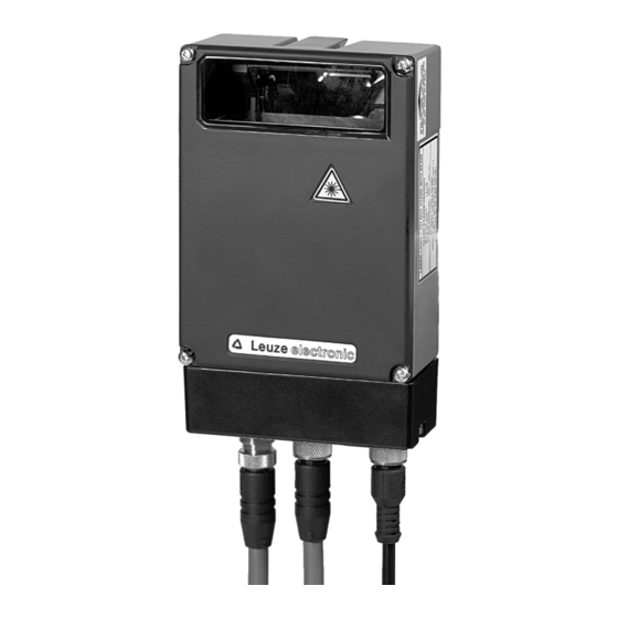
Figure 3.1: Device construction of the BPS 37 Application Wherever systems are moved automatically, it is necessary to uniquely determine their respective positions. This is achieved using various measurement procedures. In addition to mechanical measurement sensors, optical methods are particularly well suited for deter- mining positions as they operate without mechanical wear and slippage. -
Page 12: Advantages
Chapter 5. Separate data sheets are available that contain further details about the connec- tion units. With MS 37 103 connector hood The modular connector hood MS 37 103 is intended for the easy connection of the BPS 37 with M12 connection technology. BPS 37... -
Page 13: Figure 3.2: Connection Bps "Stand Alone
10 … 30 V DC 15 pin sub-D connector, socket version Figure 3.2: Connection BPS "Stand alone" With MA 4.7/MA4D.7 connection unit BPS 37 MA 4.7/MA 4D.7 Power Interconnection cable KB031-3000 Figure 3.3: BPS connection with MA 4.7 connection unit Leuze electronic... -
Page 14: Figure 3.4: Bps Connection With Ms 37 103 Modular Connector Hood
Description With MS 37 103 modular connector hood BPS 37 MS 37 103 Figure 3.4: BPS connection with MS 37 103 modular connector hood BPS 37 Leuze electronic... -
Page 15: Technical Data
Technical data Technical data General specifications BPS 37 Optical data Light source Laser diode Laser class 2 acc. to IEC 60825-1:2007 Wavelength 655nm Max. output power (peak) 1.8mW Impulse duration 120µs Scanning rate 1000 scans/s Measurement data Reproducibility (3 sigma) -
Page 16: Led Indicators
LED indicators An internal LED indicates in the reading window whether or not the supply voltage is applied. Dimensioned drawings BPS 37 S M 100 / BPS 37 S M 100 H Rear view Top view Figure 4.1: BPS 37 dimensioned drawing... -
Page 17: Figure 4.2: Ms 37 103 Dimensioned Drawing
Technical data MS 37 103 MS 37 103 Note! The BUS OUT and SW IN/OUT connections are sealed with caps upon delivery. A = BPS 37 all dimensions in mm Figure 4.2: MS 37 103 dimensioned drawing Leuze electronic BPS 37... -
Page 18: Bps 37 Reading Field Curve
Technical data BPS 37 reading field curve BPS 37 Working range Reading distance in mm Figure 4.3: BPS 37 reading field curve BPS 37 Leuze electronic... -
Page 19: Accessories/Order Codes
Accessories/order codes Accessories/order codes Accessories Note! Products from Leuze electronic GmbH & Co KG can be ordered from any of the sales and service offices listed on the back page of this operating manual. Designation Order no. Short description MA 4.7... -
Page 20: Figure 5.1: Ma 4.7/Ma 4D.7 Connection Unit / Dimensioned Drawing
Figure 5.1: MA 4.7/MA 4D.7 connection unit / dimensioned drawing MS 37 103 connector hood The modular connector hood MS 37 103 is intended for the easy connection of the BPS 37 with M12 connection technology. If offers the following advantages over the installation of the BPS 37 as a stand-alone device: •... -
Page 21: Mounting Accessories
Accessories/order codes 5.1.2 Mounting accessories The BT 56 mounting device is available for mounting the BPS 37. It is designed for rod mounting. BT 56 mounting device Clamping jaws for mounting on the BPS Clamp profile for mounting to round or oval pipes Ø... -
Page 22: Installation
Leuze electronic sales office. Observe the applicable local regulations when disposing of the packaging materials. Cleaning Clean the glass window of the BPS 37 with a soft cloth before mounting. Remove all packaging remains, e.g. carton fibers or styrofoam balls. Attention! Do not use aggressive cleaning agents such as thinner or acetone for cleaning the device and bar code tape. -
Page 23: Figure 6.1: Mounting Example Bps 37
Mounting of MA You can mount all connection units individually through the holes located on the mounting plate (see Figure 5.1). Subsequently, connect the BPS 37 with the connection unit via the respective cable (see Chapter 5.1.3). Leuze electronic BPS 37... -
Page 24: Device Arrangement
• The permitted working range is not exited Note! On the BPS 37, the beam is not emitted perpendicular to the housing cover, but with an angle of 10° towards the top. This angle is intended to prevent total reflection on the bar code tape. -
Page 25: Figure 6.2: Beam Exit On The Bps 37
Installation Minimum distance (see scanning curve) Figure 6.2: Beam exit on the BPS 37 Mounting location When choosing the mounting location, observe the following: • maintaining the required environmental conditions (humidity, temperature), • possible soiling of the reading window due to liquids, abrasion by boxes, or packaging material residues. -
Page 26: Figure 6.3: Application Example
Installation Application example Figure 6.3: Application example BPS 37 Leuze electronic... -
Page 27: Connect
Connection of the device and maintenance work while under voltage must only be carried out by a qualified electrician. The power supply unit for the generation of the supply voltage for the BPS 37 and the respective connection units must have a secure electrical insulation through double insula- tion and safety transformers according to DIN VDE 0551 (IEC 742) . -
Page 28: Connecting The Ssi Interface
TXD signal, RS 232 service interface Pin 13 Reserve Pin 14 Reserve Pin 15 Supply voltage: 0VDC Table 6.1: Connection description BPS 37 6.3.2 Connecting the SSI interface Connection with MA MA 4.7/MA 4D.7 Control/drive SSI interface Terminals Connection 1... -
Page 29: Figure 6.6: Connection Directly With Bps
(EMC couplings) is discharged via the protective conductor connection. Connecting the protective conductor PE BPS 37 without cable: connect PE to the housing of the BPS 37 or to the housing of the 15-pin SUB-D connector! BPS 37 with cable KB 031-3000:... -
Page 30: Connecting The Switching Input And Switching Output
Installation 6.3.3 Connecting the switching input and switching output The BPS 37 is provided with a switching input and a switching output. The connection of the switching input and output is made in accordance with Figure 6.7: SWIN1 12 … 30 V DC max. -
Page 31: Connection With Ms 37 103 Modular Connector Hood
6.3.4 Connection with MS 37 103 modular connector hood The BPS 37 can be connected via the MS 37 103 using M12 connectors. For the locations of the individual device connections, please refer to Figure 6.8. all dimensions in mm... -
Page 32: Figure 6.9: Pin Assignment - Pwr In
Functional earth (housing) Figure 6.9: Pin assignment - PWR IN Connecting the functional earth FE BPS 37 with MS 37 103 connector hood: Connect FE to PIN 5 of the M12 connector PWR for voltage supply! Attention! Degree of protection IP 65 is achieved only if the connectors and caps are screwed into... -
Page 33: Figure 6.10:Pin Assignment - Host/Bus In
Bridge to GND: service operation via /SERV M12 socket RS232 interface (A-coded) Thread Functional earth (housing) Figure 6.11:Pin assignment - SERVICE Attention! Degree of protection IP 65 is achieved only if the connectors and caps are screwed into place! Leuze electronic BPS 37... -
Page 34: Cable Lengths And Shielding
The following maximum cable lengths and shielding types must be observed: Connection Interface Max. cable length Shielding Absolutely required, sheath BPS 37 - Service RS 232 10 m of a shielded line Absolutely required, leads BPS 37/MA 4.7 - 1200 m... -
Page 35: Commissioning
"Power On" test After connecting the operating voltage, the BPS 37 performs an automatic "Power On" func- tion test. Subsequently, the green LED lights up in the optical window of the BPS 37. Interface Proper function of the interface can be most easily tested in service operation using the service interface with the "BPSConfig"... -
Page 36: Parameter Sets
Current parameter set In this parameter set, the current settings for all device parameters are stored. When the BPS 37 is in operation, the parameter set is stored in the EEPROM of the BPS 37. The current set can be stored: •... -
Page 37: Figure 7.1: Connecting The Service Interface To A Pc Or Terminal
Connect You can connect a PC or terminal to the BPS 37 via the serial interface and configure the BPS 37 through this connection. For this, you need a crossed RS 232 interconnection cable (null modem cable) that provides the connections RxD, TxD and GND. -
Page 38: Operation
Operation BPS 37 display elements On the BPS 37 there is an LED which signals the BPS's readiness for operation. MS 37 103 display elements On the modular connector hood there is a status LED which indicates the state of the device. -
Page 39: Communication With The Device
Insert the installation CD in your CD drive. Call up the installation file (e.g. Setup.exe) The following window appears: Installation window Figure 9.1: Installation window Confirm the following license agreement and select the installation path in the following window: Leuze electronic BPS 37... -
Page 40: Figure 9.2: Installation Directory
Communication with the device Installation directory Figure 9.2: Installation directory Confirm your entry with Next, then follow the installation routine. For further details please refer to online help of the "BPSConfig" software. BPS 37 Leuze electronic... -
Page 41: Overview Of Commands And Parameters
Online commands can be used to send commands directly to the device for control and configuration. For this, the BPS 37 has to be connected to a host or service computer via the serial inter- face. The commands described can be sent either via the host or the service interface. -
Page 42: General Parameter Structure
Settings can be made in this folder This folder contains all settings for controlling how the BPS reacts necessary for integrating the BPS to to the application of a 24 V signal. a control or drive system via an SSI interface. BPS 37 Leuze electronic... -
Page 43: Maintenance
Maintenance Maintenance 10.1 General maintenance information Usually, the bar code positioning system BPS 37 does not require any maintenance by the operator. Cleaning Clean the glass window of the BPS 37 with a soft cloth when soiled. Note! Do not use aggressive cleaning agents such as thinner or acetone for cleaning the device.
Need help?
Do you have a question about the BPS 37 and is the answer not in the manual?
Questions and answers