Advertisement
Quick Links
Advertisement

Subscribe to Our Youtube Channel
Related Manuals for Leuze electronic BCL358i


Summary of Contents for Leuze electronic BCL358i
- Page 1 Bar code reader T E C H N I C A L D E S C R I P T I O N...
- Page 2 Leuze electronic GmbH + Co. KG P.O. Box 1111, D- 73277 Owen Tel. +49(0) 7021/ 573-0, Fax +49(0)7021/ 573-199 info@leuze.de w.leuze.com Sales and Service Germany Sales Region North Sales Region South Sales Region East Phone 07021/573-306 Phone 07021/573-307 Phone 035027/629-106...
-
Page 3: Table Of Contents
4.4.2 Line scanner with oscillating mirror....................31 4.4.3 Raster scanner (raster line) ......................32 Fieldbus systems ......................33 4.5.1 EtherNet/IP ..........................33 4.5.2 Ethernet – star topology....................... 34 4.5.3 Ethernet – linear topology......................35 Heater ..........................35 Leuze electronic 358i... -
Page 4: Table Of Contents
Ultra Low Density (L) - optics: BCL 358i OL 100 (H) ..............58 Installation and mounting ................59 Storage, transportation ....................59 Mounting the BCL 358i ....................60 6.2.1 Fastening with M4 x 5 screws ......................60 6.2.2 BT 56 mounting device ........................61 6.2.3 BT 59 mounting device ........................63 358i Leuze electronic... -
Page 5: Table Of Contents
Installing the required software..................89 9.2.1 System requirements........................89 9.2.2 Installing the USB driver ......................89 Starting the webConfig tool .................... 90 Short description of the webConfig tool................ 91 9.4.1 Module overview in the Configuration menu................91 Leuze electronic 358i... -
Page 6: Table Of Contents
Online commands..................136 11.1 Overview of commands and parameters..............136 11.1.1 General ’online’ commands......................137 11.1.2 ’Online’ commands for system control ..................144 11.1.3 ’Online’ commands for configuration of switching inputs/outputs..........145 11.1.4 ’Online’ commands for the parameter set operations..............148 358i Leuze electronic... -
Page 7: Table Of Contents
14.3 Disassembling, packing, disposing ................163 Appendix ......................164 15.1 Declaration of Conformity ..................... 164 15.2 ASCII character set ......................166 15.3 Bar code samples ......................170 15.3.1 Module 0.3 ..........................170 15.3.2 Module 0.5 ..........................171 Leuze electronic 358i... -
Page 8: Table Of Contents
"Low Density" reading field curve for oscillating-mirror scanners ........56 Figure 5.17: Lateral "Low Density" reading field curve for oscillating-mirror scanners ......56 Figure 5.18: "Ultra Low Density" reading field curve for line scanner without deflection mirror....57 358i Leuze electronic... -
Page 9: Table Of Contents
Figure 10.12: Configuration of example 3 - module definition with the EDS file ........125 Figure 10.13: Data exchange sequence diagram - example 3..............127 Figure 10.14: Configuration of example 4 - module definition with generic module........ 128 Leuze electronic 358i... -
Page 10: Table Of Contents
Declaration of conformityBCL 358i ................... 164 Figure 15.2: Connection hood / connector unit declaration of conformity..........165 Figure 15.3: Bar code sample labels (module 0.3) ................170 Figure 15.4: Bar code sample labels (module 0.5) ................171 358i Leuze electronic... -
Page 11: General Information
You can find the Declaration of Conformity of the devices in the appendix of the manual on page 164. The manufacturer of the product, Leuze electronic GmbH & Co KG in D-73277 Owen, possesses a certified quality assurance system in accordance with ISO 9001. -
Page 12: Safety Notices
300i series are conceived as stationary, high-speed scanners with integrated decoders for all current bar codes used for automatic object detection. In particular, unauthorized uses include: • in rooms with explosive atmospheres • operation for medical purposes 358i Leuze electronic... -
Page 13: Working Safely
Observe the locally applicable legal regulations and the rules of the employer's liability insur- ance association. Qualified personnel Mounting, commissioning and maintenance of the device must only be carried out by qual- ified personnel. Electrical work must be carried out by a certified electrician. Leuze electronic 358i... - Page 14 If the device is opened, there is a risk of injury to the retina. Therefore, the device must not be opened. Repairs must only be performed by Leuze electronic GmbH + Co. KG. Notice! It is important that you attach the stick-on labels supplied to the device (A in figure 2.1)! If...
- Page 15 M12 MS 3xx connection hood 358i Line scanner and M12 MS 3xx connection hood Stick-on labels supplied Warning: laser aperture Name plate Figure 2.1: Attachment of the stick-on labels with warning notices at the BCL 358i Leuze electronic 358i...
-
Page 16: Fast Commissioning / Operating Principle
• The reading distance lies in the middle area of the reading field. • The bar code labels are of good print quality and have good contrast ratios. • You do not use high-gloss labels. • There is no direct sunlight. 358i Leuze electronic... - Page 17 MS 358. In the integrated parameter memory, both the settings and the network address are saved and transmitted to a new device. Notice! In the case of Ethernet line topology, the network is interrupted when the BCL 358i removed from the MS 358. Leuze electronic 358i...
- Page 18 The shield is automatically contacted when the cable is lead into the metal screw fitting and fastened when the cord grip is closed. Then lead the individual wires into the terminals according to the diagram. Wire end sleeves are not necessary. 358i Leuze electronic...
-
Page 19: Preparatory Ethernet/Ip Settings
In this case, the respective configuration must be entered and adapted manually for each device. The parameter download from the control to the BCL 358i is performed during every establishment of connection. Since the parameters are stored centrally in the control, this helps during device exchange. Leuze electronic 358i... -
Page 20: Manually Setting The Ip Address
• Set these values on the BCL 358i. Via webConfig: Configuration -> Communication -> Ethernet interface Notice! If the IP address is set via the webConfig tool, then it becomes active after transfer to the device. A restart is not required. 358i Leuze electronic... -
Page 21: Configure The Participant
122; min 1 byte - up to max. 263 bytes for the default output assembly). • The address and length of the configuration assembly (instance 190; 3 bytes). For the exact description of the assemblies for input/output and configuration, please refer to chapter 10. Leuze electronic 358i... -
Page 22: Transfering The Data To The Control (Rslogix 5000 Specific)
• Control of the switching outputs Configure the connected switching outputs according to your requirements. To do this, first set the I/O mode to Output and then configure the switching behavior: • Via webConfig: Configuration -> Device -> Switching inputs/outputs 358i Leuze electronic... -
Page 23: Starting The Device
LED self test, no EtherNet/IP communication, no master assignment green continuous light Bus communication ok red flashing LED self test, time out in the bus communication red continuous light Double IP address green/red flashing Self test Leuze electronic 358i... - Page 24 2/5 Interleaved code type is limited to 10 digits of code content. If a code is moved through the reading field, the code content is decoded and forwarded to the superior system (PLC/PC) via the Ethernet. 358i Leuze electronic...
-
Page 25: Bar Code Reading
(PLC/PC) via the Ethernet. Please check the incoming data of the bar code information there. Alternatively, you can use a switching input for read activation (switching signal of a photoelectric sensor or 24VDC switching signal). Leuze electronic 358i... -
Page 26: Device Description
The interfaces (RS 232, RS 485 and RS 422) integrated in the various device models and the fieldbus systems (PROFIBUS DP, PROFINET-IO, Ethernet TCP/IP UDP and EtherNet/IP) offer optimum connection to the superior host system. 358i Leuze electronic... - Page 27 CRT decoder with code fragment technology: The proven code fragment technology (CRT) enables bar code readers of the BCL 300i series to read bar codes with a small bar height, as well as bar codes with a damaged or soiled print image. Leuze electronic 358i...
- Page 28 The two freely configurable switching inputs/outputs SWIO1 and SWIO2 can be assigned various functions and control e.g. activation of the BCL 358i or external devices, such as a PLC. System, warning and error messages provide assistance in setup/troubleshooting during commissioning and read operation. 358i Leuze electronic...
-
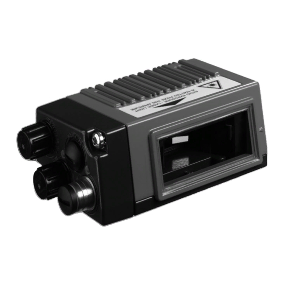
Page 29: Device Construction
Connection side for: MK 3xx terminal hood MS 3xx connector hood Display, LEDs and buttons Reading window Dovetail mounting and 4 mounting threads Line scanner with deflection mirror Figure 4.4: 358i device construction - line scanner with deflection mirror Leuze electronic 358i... - Page 30 Device description Connection side for: MK 3xx terminal hood MS 3xx connector hood Display, LEDs and buttons Dovetail mounting and 6 mounting threads Reading window Oscillating-mirror scanner Figure 4.5: 358i device construction - oscillating-mirror scanner 358i Leuze electronic...
- Page 31 Device construction MS 358 connector hood MK 358 terminal hood Cable lead-throughs Terminal compartment Ethernet LEDs LINK / ACT Connection side with system plug for Mini-B type USB connection to service interface 358i Figure 4.7: Device construction MK 358 terminal hood Leuze electronic 358i...
-
Page 32: Reading Techniques
• with bar codes having very short bar lengths. • when the ladder code is turned out of the vertical position (tilt angle). • when the reading distance is large. Figure 4.8: Deflection principle for the line scanner 358i Leuze electronic... -
Page 33: Line Scanner With Oscillating Mirror
• when the bars of the bar code are printed perpendicular to the conveying direction ('picket fence arrangement'). • when reading stationary objects. • when a large reading field (reading window) has to be covered. Figure 4.9: Deflection principle for the line scanner with oscillating mirror add-on Leuze electronic 358i... -
Page 34: Raster Scanner (Raster Line)
• when the bars of the bar code are perpendicular to the conveying direction ('picket fence arrangement') • with bar codes with low height displacement • with very glossy bar codes Figure 4.10: Deflection principle for the raster scanner 358i Leuze electronic... -
Page 35: Fieldbus Systems
• BootP Notice! The BCL 358i communicates via the Common Industrial Protocol (CIP). CIP Safety, CIP Sync and CIP Motion are not supported by the BCL 358i. Further information on commissioning can be found in chapter 10. Leuze electronic 358i... -
Page 36: Ethernet – Star Topology
MS 358 connector hood 192.168.60.xxx Other network participants 358i with MK 358 terminal hood 192.168.60.yyy Figure 4.11: Ethernet with star topology Notice! The BCL 358i does not support the DLR (Device Level Ring) ring structure determined by the ODVA. 358i Leuze electronic... -
Page 37: Ethernet – Linear Topology
For low-temperature applications to min. -35°C (e.g. in cold storage), the bar code readers of the BCL 358i series can optionally be permanently fitted with a built-in heating and these bar code readers purchased as separate device models. Leuze electronic 358i... -
Page 38: Autoreflact
It is possible to store the reference codes via the webConfig tool or via online commands. The BCL 358i can compare read bar codes with one and/or both reference codes and execute user-configurable functions depending on the comparison result. 358i Leuze electronic... -
Page 39: Autoconfig
BCL 358i. Afterward, bar codes with the same code type and number of digits are recognized and decoded. Leuze electronic 358i... -
Page 40: Specifications
Display Monochromatic graphical display, 128 x 32 pixel, with background lighting Keyboard 2 buttons LEDs 2 LEDs for power (PWR) and bus state (NET), two-colored (red/green) Table 5.1: Specifications of the BCL 358i line/raster scanners without heating 358i Leuze electronic... - Page 41 For UL applications, use is permitted exclusively in Class 2 circuits according to NEC (National Electric Code). The BCL 358i bar code readers are designed in accordance with safety class III for supply by PELV (protective extra-low voltage). Leuze electronic 358i...
-
Page 42: Oscillating-Mirror Scanner
Via rotating polygon wheel (horizontal) and deflection mirror (vertical) Electrical data Power consumption Max. 4.5W Mechanical data Weight 350g (without connection hood) 44 x 103 x 96mm (without connection hood) Dimensions (WxHxD) Table 5.3: Specifications of the BCL 358i deflection mirror scanners without heating 358i Leuze electronic... -
Page 43: Heating Models Of The Bar Code Readers
To achieve an optimal heating effect, the BCL 358i should be mounted so that it is thermally isolated. Electrical connection The required core cross section of the connection cable for the voltage supply must be at least 0.75 mm². Leuze electronic 358i... -
Page 44: Line Scanner / Raster Scanner With Heater
Specifications same as for line scanner without heating with the following differences: Type 358i EtherNet/IP Type Oscillating-mirror scanner with heating Optical data Useful opening angle Max. 60° Max. swivel angle ± 20°(adjustable) Table 5.5: Specifications of the BCL 358i oscillating-mirror scanners with heating 358i Leuze electronic... -
Page 45: Line Scanner / Raster Scanner With Deflection Mirror And Heating
Wiring through of the voltage supply to multiple heating devices is not permissible. Standard, M12 ready-made cable not usable (insufficient cable cross-section) Environmental data Operating temperature range -35°C … +40°C Storage temperature range -20°C … +70°C Table 5.6: Specifications of the BCL 358i deflection mirror scanners with heating Leuze electronic 358i... -
Page 46: Dimensioned Drawings
Specifications Dimensioned drawings 5.3.1 Dimensioned drawing of complete overview of the BCL 358i with MS 3xx / MK 3xx Figure 5.1: Dimensioned drawing of complete overview of the BCL 358i with MS 3xx / MK 3xx 358i Leuze electronic... -
Page 47: Dimensioned Drawing Of Line Scanner With / Without Heating
Specifications 5.3.2 Dimensioned drawing of line scanner with / without heating depth Laser beam exit Max. scanning angle Range of the laser beam Figure 5.2: Dimensioned drawing BCL 358i line scanner S…102 Leuze electronic 358i... -
Page 48: Dimensioned Drawing Of Deflection Mirror Scanner With / Without Heating
Specifications 5.3.3 Dimensioned drawing of deflection mirror scanner with / without heating depth Laser beam exit Max. scanning angle: 60° Range of the laser beam Figure 5.3: Dimensioned drawing BCL 358i deflection mirror scanner S…100 358i Leuze electronic... -
Page 49: Dimensioned Drawing Of Oscillating-Mirror Scanner With / Without Heating
Specifications 5.3.4 Dimensioned drawing of oscillating-mirror scanner with / without heating depth Laser beam exit Max. scanning angle Range of the laser beam Figure 5.4: Dimensioned drawing BCL 358i oscillating mirror scanner O…100 Leuze electronic 358i... -
Page 50: Dimensioned Drawing Of Ms 3Xx Connector Hood / Mk 3Xx Terminal Hood
To ensure protection class IP 65 is fulfilled, the screws of the connection hood are tightened with a tightening torque of 1.4Nm for connecting to the BCL. Figure 5.5: Dimensioned drawing of MS 3xx connector hood / MK 3xx terminal hood 358i Leuze electronic... -
Page 51: Reading Field Curves / Optical Data
Therefore, above all, the module of a bar code is decisive for the size of the reading field. Notice! A rule of thumb: The smaller the module of the bar code is, the smaller the maximum reading distance and reading field width will be. Leuze electronic 358i... -
Page 52: Raster Scanner
8 scan lines which vary depending on the reading distance from the raster aperture. Distance [mm] starting at the zero position Front scanner Deflection mirror scanner Table 5.7: Raster line cover as a function of the distance 358i Leuze electronic... -
Page 53: Reading Field Curves
BCL 3xxi O…100… Figure 5.7: Zero position of the reading distance Reading conditions for the reading field curves 2/5 Interleaved Bar code type 1:2.5 Ratio class A ANSI specification > 75% Reading rate Table 5.8: Reading conditions Leuze electronic 358i... - Page 54 = 0,127 m = 0,15 m = 0,2 -100 Reading distance [mm] Figure 5.9: "High Density" reading field curve for line scanner with deflection mirror The reading field curve applies for the reading conditions stated in table 5.8. 358i Leuze electronic...
-
Page 55: Figure 5.10: "Medium Density" Reading Field Curve For Line Scanner Without Deflection Mirror
= 0,3 m = 0,5 -100 -150 Reading distance [mm] Figure 5.11: "Medium Density" reading field curve for line scanner with deflection mirror The reading field curves apply for the reading conditions stated in table 5.8. Leuze electronic 358i... -
Page 56: Figure 5.12: "Medium Density" Reading Field Curve For Oscillating-Mirror Scanners
= 0,2 m = 0,3 m = 0,5 -100 -125 -150 Reading distance [mm] Figure 5.13: Lateral "Medium Density" reading field curve for oscillating-mirror scanners The reading field curves apply for the reading conditions stated in table 5.8. 358i Leuze electronic... -
Page 57: Figure 5.14: "Low Density" Reading Field Curve For Line Scanner Without Deflection Mirror
= 0,35 m = 0,5 -100 -150 -200 Reading distance [mm] Figure 5.15: "Low Density" reading field curve for line scanner with deflection mirror The reading field curves apply for the reading conditions stated in table 5.8. Leuze electronic 358i... -
Page 58: Figure 5.16: "Low Density" Reading Field Curve For Oscillating-Mirror Scanners
= 0,3 m = 0,35 m = 0,5 -100 -150 -200 Reading distance [mm] Figure 5.17: Lateral "Low Density" reading field curve for oscillating-mirror scanners The reading field curves apply for the reading conditions stated in table 5.8. 358i Leuze electronic... -
Page 59: Figure 5.18: "Ultra Low Density" Reading Field Curve For Line Scanner Without Deflection Mirror
= 0,8 -100 -150 -200 -250 -300 Reading distance [mm] Figure 5.19: "Ultra Low Density" reading field curve for line scanner with deflection mirror The reading field curves apply for the reading conditions stated in table 5.8. Leuze electronic 358i... -
Page 60: Figure 5.20: "Ultra Low Density" Reading Field Curve For Oscillating-Mirror Scanners
= 0,5 m = 0,8 -100 -150 -200 -250 -300 Reading distance [mm] Figure 5.21: Lateral "Ultra Low Density" reading field curve for oscillating-mirror scanners The reading field curves apply for the reading conditions stated in table 5.8. 358i Leuze electronic... -
Page 61: Installation And Mounting
Device name plate BCL 358i Save the original packaging for later storage or shipping. Notice! All BCL 358i are delivered with a protective cover on the connection side which must be removed before attaching a connection hood. Leuze electronic 358i... -
Page 62: Fastening With M4 X 5 Screws
Installation and mounting If you have any questions concerning your shipment, please contact your supplier or your local Leuze electronic sales office. Observe the applicable local regulations when disposing of the packaging materials. Mounting the BCL 358i The BCL... -
Page 63: Bt 56 Mounting Device
358i Clamp profile for fastening to round or oval pipes Ø 16 … 20mm All dimensions in mm A Rod holder, turnable 360° B Rods Ø 16 … 20mm Figure 6.3: BT 56 mounting device Leuze electronic 358i... -
Page 64: Figure 6.4: Mounting Example Of Bcl 358I With Bt 56
Installation and mounting Figure 6.4: Mounting example of BCL 358i with BT 56 358i Leuze electronic... -
Page 65: Bt 59 Mounting Device
For further information, see the notices in chapter 6.3! Please refer to chapter 5.4 for the permissible minimum and maximum distances between the BCL 358i and the labels to be read. Leuze electronic 358i... -
Page 66: Device Arrangement
• The reading distance lies in the middle area of the reading field. • The bar code labels are of good print quality and have good contrast ratios. • You do not use high-gloss labels. • There is no direct sunlight. 358i Leuze electronic... -
Page 67: Avoiding Total Reflection – Line Scanner
358i can be installed parallel to the bar code (rear housing wall). The BCL 358i with deflection mirror should be mounted Bar code parallel to the bar code. Zero position Figure 6.7: Total reflection – line scanner Leuze electronic 358i... -
Page 68: Avoiding Total Reflection – Oscillating-Mirror Scanner
• Possible soiling of the reading window due to liquids, abrasion by boxes, or packaging material residues. • Lowest possible chance of damage to the BCL 358i by mechanical collision or jammed parts. • Possible extraneous light (no direct sunlight or sunlight reflected by the bar code). 358i Leuze electronic... -
Page 69: Devices With Integrated Heating
(figure 6.9). β α γ γ Figure 6.9: Reading angle for the line scanner Tilt Angle of inclination (Pitch) Skew In order to avoid total reflection, the skew should be greater than 10°. Leuze electronic 358i... -
Page 70: Cleaning
Styrofoam balls. In doing so, avoid leaving finger- prints on the front cover of the BCL 358i. Attention! Do not use aggressive cleaning agents such as thinner or acetone for cleaning the device. 358i Leuze electronic... -
Page 71: Electrical Connection
Minimum tightening torque of the housing connection screws on the connection hood 1.4Nm! Location of the electrical connections Oscillating-mirror scanner Line scanner with deflection mirror Line scanner MK 358 MS 358 Terminals M12 connector Figure 7.1: Location of the electrical connections Leuze electronic 358i... -
Page 72: Safety Notices For The Electrical Connection
Protection class IP 65 is not fulfilled until connectors or cable lead-throughs are screwed on and caps are installed! Attention! To ensure protection class IP 65 is fulfilled, the screws of the connection hood are tightened with a tightening torque of 1.4Nm for connecting to the BCL. 358i Leuze electronic... -
Page 73: Ms 358 Connector Hood With 3 Integrated M12 Connectors
The integrated parameter memory for the simple replacement of the BCL 358i is located in the MS 358. In the integrated parameter memory, both the settings and the network address are saved and transmitted to a new device. Leuze electronic 358i... -
Page 74: Mk 358 Terminal Hood With Spring-Loaded Terminals
MK 358. In the integrated parameter memory, both the settings and the network address are saved and transmitted to a new device. Notice! In the case of Ethernet line topology, the network is interrupted when the BCL 358i removed from the MK 358. 358i Leuze electronic... -
Page 75: Figure 7.4: Cable Fabrication For Mk 358 Terminal Hood
Then lead the individual wires into the terminals according to the diagram. Wire end sleeves are not necessary. Notice! See chapter 5.4 "Reading field curves / optical data" dimensioned drawing on page 49. Leuze electronic 358i... -
Page 76: Detailed Description Of The Connections
Connecting functional earth FE Ensure that the functional earth (FE) is connected correctly. Unimpaired operation is only guaranteed when the functional earth is connected properly. All electrical disturbances (EMC couplings) are discharged via the functional earth connection. 358i Leuze electronic... - Page 77 If, for example, the inverted sensor output is connected to pin 2, and pin 2 of the bar code reader is, at the same time, configured as an output (and not as an input), the switching output malfunctions. Attention! The maximum input current must not exceed 8mA! Leuze electronic 358i...
- Page 78 60mA at +18 … +30VDC in normal operation! Notice! Both switching inputs/outputs SWIO_1 and SWIO_2 are configured by default in such a way that: • Switching input SWIO_1 activates the reading gate. • Switching output SWIO_2 switches by default on "No Read." 358i Leuze electronic...
-
Page 79: Service – Usb Interface (Mini-B Type)
Use the Leuze specific USB service cable (See chapter 13 "Type overview and acces- sories") for the connection and use a service PC to configure. Notice! IP 65 is achieved only if the connectors and caps are screwed into place. Leuze electronic 358i... - Page 80 HOST / BUS IN cable assignments on RJ-45 Notice for connecting the Ethernet interface! Ensure adequate shielding. The entire connection cable must be shielded and earthed. The RD+/RD- and TD+/TD- wires must be stranded in pairs. Use CAT 5 cable for the connection. 358i Leuze electronic...
- Page 81 Use CAT 5 cable for the connection. Notice! For the BCL 358i as standalone device or as the last participant in a linear topology, termi- nation on the BUS OUT socket is not mandatory! Leuze electronic 358i...
-
Page 82: Ethernet Topologies
In addition to the classic "star topology", a "linear topology" is thus also possible. This makes wiring the network easy and inexpensive as slaves are looped through to one another in parallel. The maximum length of a segment (connection between two switches/BCL 358i) is limited to 100m. 358i Leuze electronic... -
Page 83: Ethernet Wiring
TDx+ on the M12 connector with RD+ on the RJ-45 connector and TDx- on the M12 connector with RD- on the RJ-45 connector, respectively, etc. Notice! Use the recommended connectors / sockets or the ready-made cables (See chapter 13 "Type overview and accessories"). Leuze electronic 358i... -
Page 84: Cable Lengths And Shielding
EtherNet twisted pairs (min. Cat. 3) and last BCL shielded 100Base-TX twisted pair (min. Cat. 5) BCL – power not necessary supply unit not necessary Switching input not necessary Switching output Table 7.5: Cable lengths and shielding 358i Leuze electronic... -
Page 85: Display Elements And Display
- self test runs for 0.25s after power up - initialization running green continuous light Device ok - bar code reading possible - self test successfully finished - device monitoring active green, briefly off - on Good read, successful reading - bar code(s) successfully read Leuze electronic 358i... - Page 86 NET LED flashes red - LED self test runs for 0.25s after power up - time-out in bus communication red continuous light NET LED red - double IP address green/red flashing NET LED flashes green/red - self test 358i Leuze electronic...
-
Page 87: Ms 358/Mk 358 Led Indicators
LED ACT0 / LINK0 (on the MS 358/MK 358) green continuous light Ethernet connected (LINK) yellow flashing Data communication (ACT) LED ACT1 / LINK1 (on the MS 358/MK 358) green continuous light Ethernet connected (LINK) yellow flashing Data communication (ACT) Leuze electronic 358i... - Page 88 • BCL Info = device status/error code • I/O Status = status of the in/outputs • BCL Address = IP address of the BCL 358i • Adjustmode = alignment mode • Version = software and hardware version 358i Leuze electronic...
- Page 89 • 1st line: alignment mode display function • 2nd line: decoding quality in percent, e.g. 73% Version • 1st line: version display function SW: xxxxx HW: xxx • 2nd line: software and hardware version of the device Leuze electronic 358i...
-
Page 90: Leuze Webconfig Tool
The SERVICE USB interface of the BCL 358i is connected via the PC -side USB interface by means of a standard USB cable, with 1 type A connector and 1 Mini-B type connector. Mini-B Figure 9.1: Connecting the SERVICE USB interface 358i Leuze electronic... -
Page 91: Installing The Required Software
Upon successful installation of the USB driver, an icon with the name Leuze Web Config automatically appears on the desktop. Notice! If the installation failed, contact your network administrator: The settings of the firewall used may need to be adjusted. Leuze electronic 358i... -
Page 92: Starting The Webconfig Tool
The individual parameters are – where useful – graphically displayed in order to better illus- trate the meaning of the what are often perceived as abstract parameters. The result is an easy-to-use and practically-oriented user interface! 358i Leuze electronic... -
Page 93: Short Description Of The Webconfig Tool
The user interface of the webConfig tool is largely self-explanatory. 9.4.1 Module overview in the Configuration menu The adjustable parameters of the BCL 358i are clustered in modules in the Configuration menu. Figure 9.3: Module overview in the webConfig tool Leuze electronic 358i... -
Page 94: Oscillating Mirror
Configuration of the oscillating mirror settings Notice! On the right side of the user interface of the webConfig tool, you will find a description of the individual modules and functions as a help text in the Information area. 358i Leuze electronic... -
Page 95: Commissioning And Configuration
Before commissioning, familiarize yourself with the operation and configuration of the BCL 358i. Before connecting the supply voltage, recheck all connections and ensure that they have been properly made. The description of the electrical connections can be found in chapter 7. Leuze electronic 358i... - Page 96 The communication parameters are independent of the topology in which the BCL 358i is operated. See "Ethernet topologies" on page 80. On delivery, the automatic address assignment via DHCP server is defined as the standard setting of the BCL 358i. 358i Leuze electronic...
- Page 97 In the main menu, select Configuration, submenu Communication -> Ethernet interface. • Deactivate the DHCP operation and enter the IP address. Notice! If the IP address is set via the webConfig tool, then it becomes active after transfer to the device. A restart is not required. Leuze electronic 358i...
-
Page 98: Configuration Steps For A Rockwell Control Without Eds Support
• The address and length of the output assembly (instance 120, instance 121 or instance 122; min 1 byte - up to max. 263 bytes for the default output assembly) • The address and length of the configuration assembly (instance 190; 3 bytes) 358i Leuze electronic... -
Page 99: Configuration Steps For A Rockwell Control With Eds Support
• After it has downloaded, select the device from the device list. • Open the input dialog for setting the address and additional parameters by double- clicking on the device symbol and make the desired entries here. Under Change, define the combination of input and output assemblies. Leuze electronic 358i... -
Page 100: Eds File - General Info
358i is uniquely classified via a class 1 identity object (component of the BCL358i.eds file) for the EtherNet/IP scanner. The identity object contains, among other things, a manufacturer-specific vendor ID, as well as an ID that describes the principle func- tion of the participant. -
Page 101: Detailed Eds Description
(max. 32) SHORT_STRING "BCL 358i" In the network configuration (e.g., RSLogix 5000, generic module), it is possible to specify when entering the individual participants which attributes of the scanner are to be monitored from the identity object. Leuze electronic 358i... - Page 102 According to ODVA, the BCL 358i is assigned number 43 = 0x2B. Product Code The product code is an ID assigned by Leuze electronic that has no further impact on other objects. Revision Version number of the identity object. Status The device status is displayed in the status byte, the first part of the telegram.
-
Page 103: Class 4 - Assembly
Formula for calculating the assembly length: Length of the assembly = 5 + length of the result/bar code For results/bar codes with length 10, the assembly must be configured with a length of 5 + 10 = 15. Leuze electronic 358i... - Page 104 Formula for calculating the assembly length: Length of the assembly = 9 + length of the result/bar code. For results/bar codes with length 10, the assembly must be configured with a length of 9 + 10 = 19. 358i Leuze electronic...
- Page 105 Formula for calculating the assembly length: Length of the assembly = 10 + length of the result/bar code. For results/bar codes with length 10, the assembly must be configured with a length of 10 + 10 = 20. Leuze electronic 358i...
- Page 106 Formula for calculating the assembly length: Length of the assembly = 8 + length of the entry data. For entry data with length 10, the assembly must be configured with a length of 8 + 10 = 18. 358i Leuze electronic...
- Page 107 Formula for calculating the assembly length: Length of the assembly = 7 + length of the entry data. For entry data with length 10, the assembly must be configured with a length of 7 + 10 = 17. Leuze electronic 358i...
- Page 108 Formula for calculating the assembly length: Length of the assembly = 6 + length of the entry data. For entry data with length 10, the assembly must be configured with a length of 6 + 10 = 16. 358i Leuze electronic...
- Page 109 In the configuration assembly, all parameters have the value 0. Changing the individual default values is possible at any time. The participant is thereby defined in offline mode; the data must subsequently be transferred to the control. Leuze electronic 358i...
-
Page 110: Class 103 - I/O Status And Control
Switching output 0 - low - inactive Switching output 1 - high - active Reset Event Counter Resets the event counter of the activation function back to zero 0 1 perform reset 1 0 no function 358i Leuze electronic... - Page 111 If SWOUT switches several times was configured as comparison mode, this bit is toggled each time the event counter is exceeded. The bit is reset to the init. value by resetting the event counter. 0 1 event counter exceeded 1 0 event counter exceeded again Leuze electronic 358i...
-
Page 112: Class 106 - Activation
This control bit signals that the transmitted data have been processed by the master. Only relevant with handshake mode (with ACK), see Mode. 0 1 data has been processed by the master 1 0 data has been processed by the master 358i Leuze electronic... - Page 113 0 1 data reset If the data reset control bit is activated, the following actions are carried out: Deletion of results that may still be stored. Resetting of the attributes of Class 107 - Result data Leuze electronic 358i...
-
Page 114: Class 107 - Result Data
Displays the current activation status. deactivated activated User data or command Distinction between result from the Formatter and answer from the command interpreter. Makes the distinction easy for the user. user data answer from the command interpreter 358i Leuze electronic... - Page 115 Fragment number Current fragment number Remaining fragments Number of fragments which still have to be read for a complete result. Fragment size Fragment size always corresponds to the configured fragment length, except for the last fragment. Leuze electronic 358i...
-
Page 116: Class 108 - Entry Data
Data rejection (toggle bit) The BCL 358i has rejected the acceptance of the data or the data fragment (also see Data acceptance toggle bit). 0 1 data have been rejected 1 0 data have been rejected 358i Leuze electronic... -
Page 117: Figure 10.4: Connection Between Data Acceptance/Data Rejection/Error Code Attributes
Data rejection (toggle bit) Error code Input-Assembly Figure 10.4: Connection between Data acceptance/Data rejection/Error code attributes New entry (toggle bit) The toggle bit shows whether new entry data are present. 0 1 new result 1 0 new result Leuze electronic 358i... - Page 118 Number of fragments which still have to be transmitted for a complete entry. Fragment size The fragment size should always be identical, except for the last fragment to be transferred. A fragement size of 0 means that the fragmentation is not used. 358i Leuze electronic...
-
Page 119: Class 109 - Device Status And Device Control
This control bit confirms and deletes errors or warnings that may be present in the system. It acts like a toggle bit. 0 1 error acknowledge 1 0 error acknowledge StandBy Activates the standby function. standby off standby on Leuze electronic 358i... -
Page 120: Configuration Example
2 bytes Config: 0 bytes • Example 3 - activation & fragmented result 13 bytes Out: 1 byte Config: 3 bytes • Example 4 - entry data & result 33 bytes Out: 10 bytes Config: 0 bytes 358i Leuze electronic... -
Page 121: Example 1 - Activation & Result
The following screenshot shows the configuration of the device in the RSLogix 5000 control software. Figure 10.5: Configuration of example 1 - module definition with generic module Figure 10.6: Configuration of example 1 - module definition with the EDS file Leuze electronic 358i... - Page 122 Structure of configuration assembly 190 Since the configuration is not used, the length of the configuration assembly is specified as 0. The device then operates with the default values. In this case, the acknowledge mode is not used. 358i Leuze electronic...
-
Page 123: Figure 10.7: Data Exchange Sequence Diagram - Example 1
User data / command New result (toggle bit) Result data length = 11 Data = "TestLabel01" Result is transmitted to Input-Assembly the PLC Activation signal Deactivation signal via Output-Assembly Figure 10.7: Data exchange sequence diagram - example 1 Leuze electronic 358i... -
Page 124: Example 2 - Activation & Result & I/Os
The following screenshot shows the configuration of the device in the RSLogix 5000 control software. Figure 10.8: Configuration of example 2 - module definition with generic module Figure 10.9: Configuration of example 2 - module definition with the EDS file 358i Leuze electronic... - Page 125 Below, examples of what data exchange looks like during two subsequent activations are shown. Switching output 1 reflects the activation signal. Switching output 2 displays whether the result is valid (status input/output I/O 2 = 1] or whether a NoRead has taken place (status input/output I/O 2 = 0). Leuze electronic 358i...
-
Page 126: Figure 10.10: Data Exchange Sequence Diagram - Example 2
Fragment size Number of results Activation status User data / command New result (toggle bit) Result data length Data = "?" Result is transmitted to the PLC Input-Assembly Figure 10.10: Data exchange sequence diagram - example 2 358i Leuze electronic... -
Page 127: Example 3 - Activation & Fragmented Result
The following screenshot shows the configuration of the device in the RSLogix 5000 control software. Figure 10.11: Configuration of example 3 - module definition with generic module Figure 10.12: Configuration of example 3 - module definition with the EDS file Leuze electronic 358i... - Page 128 106 / 1 / 1 – – – – – – – 0x00 107 / 1 / 9 – – – – – – – 0x00 108 / 1 / 8 – – – – – – – 0x00 358i Leuze electronic...
-
Page 129: Figure 10.13: Data Exchange Sequence Diagram - Example 3
Number of results Activation status User data / command New result (toggle bit) Waiting for acknowledgement Result data length Result is transmitted to Data = "" the PLC Input-Assembly Figure 10.13: Data exchange sequence diagram - example 3 Leuze electronic 358i... -
Page 130: Example 4 - Entry Data & Result
The following screenshot shows the configuration of the device in the RSLogix 5000 control software. Figure 10.14: Configuration of example 4 - module definition with generic module Figure 10.15: Configuration of example 4 - module definition with the EDS file 358i Leuze electronic... - Page 131 Structure of configuration assembly 190 Since the configuration is not used, the length of the configuration assembly is specified as 0. The device then operates with the default values. In this case, the acknowledge mode is not used. Leuze electronic 358i...
-
Page 132: Figure 10.16: Data Exchange Sequence Diagram - Example 4
Entry data length Data = "-" – command Output-Assembly Number of results Activation status User data / command New result (toggle bit) Result data length Data = "?" Result Input-Assembly Figure 10.16: Data exchange sequence diagram - example 4 358i Leuze electronic... -
Page 133: Decoding And Processing The Read Data
The two possibilities for the latter are Standard (corre- sponds to the standard for the selected code type/symbology) and not Standard. Define at least one code type with the desired settings. • Via webConfig: Configuration -> Decoder Leuze electronic 358i... - Page 134 Configuration of up to 3 different sorting criteria. Sorting by physical data and con- tent of the read bar codes. • Formatting of the data output for the HOST. • Formatting of the data output for the display. 358i Leuze electronic...
-
Page 135: Control Of The Decoding
• stop decoding after a maximum reading gate time • stop decoding via the completeness mode, if: • the maximum number of bar codes to be decoded has been decoded • a positive reference code comparison has taken place. Leuze electronic 358i... -
Page 136: Control Of The Switching Outputs
As described in chapter 7 of the manual, connect the required switching outputs. Configure the connected switching outputs according to your requirements. To do this, first set the I/O mode to Output and then configure the switching behavior: • Via webConfig: Configuration -> Device -> Switching inputs/outputs 358i Leuze electronic... -
Page 137: Transmitting Configuration Data
Recommission the new BCL 358i (reconnect the voltage supply). The configuration is now imported from the external parameter memory of the connection hood and the BCL 358i is immediately operational without any further configuration. Leuze electronic 358i... -
Page 138: Online Commands
’ ’ in the text of this manual. Most online commands are acknowledged by the BCL 358i and any requested data returned. For commands that are not acknowledged, command execution can be observed or monitored directly on the device. 358i Leuze electronic... -
Page 139: General 'Online' Commands
Software reset Command ’H’ Carries out a software reset. The device is restarted and reinitialized, Description leaving it in the same state as when the supply voltage is switched on. Parameter Acknowledgment ’S’ (start signal) Leuze electronic 358i... - Page 140 Code 93 ’13’ GS1 DataBar OMNIDIRECTIONAL ’14’ GS1 DataBar LIMITED ’15’ GS1 DataBar EXPANDED Number of digits of the read code Contents of the decoded label. A appears if the label was zzzzzz: not correctly read. 358i Leuze electronic...
- Page 141 Code 128, EAN 128 ’10’ EAN Addendum ’11’ Codabar ’12’ Code 93 ’13’ GS1 DataBar OMNIDIRECTIONAL ’14’ GS1 DataBar LIMITED ’15’ GS1 DataBar EXPANDED Contents of the decoded label. A appears if the label zzzzzz: was not correctly read. Leuze electronic 358i...
- Page 142 ’+’: Starts the adjustment mode. Parameter ’-’: Ends the adjustment mode. ’yyy_zzzzzz’ Acknowledg- yyy: Reading quality in %. A high process availability is ensured at ment read qualities > 75%. zzzzzz: Bar code information. 358i Leuze electronic...
- Page 143 Valid ’Rx’ command Acknowledgment ’1’ Invalid command ’2’ Insufficient memory for reference code ’3’ Reference code has not been saved ’4’ Reference code invalid Input = ’RS130678654331’ (Code 1 (1), RAM only (3), UPC (06), code Example information) Leuze electronic 358i...
- Page 144 After each reading via an ’RTy’ command, explicitly switch off the function again since failure to do so will interfere with other commands as well as prevent execution of a new ’RTx’ command. 358i Leuze electronic...
- Page 145 (variables) for the actual input. Defined reference code no. Acknowledgment ’1’ (Code 1) ’2’ (Code 2) Memory location for reference code ’0’ RAM+EEPROM, ’3’ RAM only Defined code type (see command ’CA’) Defined code information (1 … 63 characters) Leuze electronic 358i...
-
Page 146: Online' Commands For System Control
The command deactivates decoding. This command can be used to deactivate the reading gate. Following deactivation, the read result is Description output. Because the reading gate was manually deactivated and, thus, no GoodRead criterion was met, a NoRead is output. Parameter Acknowledgment None 358i Leuze electronic... -
Page 147: Online' Commands For Configuration Of Switching Inputs/Outputs
(e.g., inverted logic and a state of High corresponds to a voltage of 0V at the switching output). Parameter ’OA?’ ’OA S1=<a>;S2=<a>’ <a> State of the switching outputs ’0’ Acknowledgment ’1’ High ’I’ Configuration as switching input ’P’ Passive configuration Leuze electronic 358i... - Page 148 The logic state is output, i.e., an inverted logic is taken into account (e.g., inverted logic and a state of High corresponds to a voltage of 0V at the switching output). ’OD<a>’ Parameter <a> Selected switching output [1, 2], unit (dimensionless) Acknowledgment None 358i Leuze electronic...
- Page 149 ’OF [S1=<a>][;S2=<a>]’ <a> Function of the switching input/ output, unit [dimension- less]’ Parameter ’I Switching input ’O’ Switching output ’P’ Passive ’OF=<bb>’ <bb> Status acknowledgment ’00’ Acknowledgment ’01’ Syntax error ’02’ Parameter error ’03’ Other error Leuze electronic 358i...
-
Page 150: Online' Commands For The Parameter Set Operations
Copying the default parameters to the permanent memory and to the main memory ’PS=<aa>’ <aa> Status acknowledgment, unit [dimensionless] ’00’ ’01’ Syntax error Acknowledgment ’02’ Impermissible command length ’03’ Reserved ’04’ Reserved ’05’ Reserved ’06’ Impermissible combination, source type - target type 358i Leuze electronic... - Page 151 <Address> Relative address of the data within the data set ’aaaa’ Four-digit, unit [dimensionless] <Data length> Length of the parameter data to be transferred ’bbbb’ Four-digit, unit [length in bytes] <BCC> Check sum calculated as specified under BCC type Leuze electronic 358i...
- Page 152 ’05’ Impermissible number of data requested ’06’ Requested data does not (any longer) fit in the transmis- sion buffer ’07’ Impermissible address value ’08’ Read access after end of data set ’09’ Impermissible QPF data set type 358i Leuze electronic...
- Page 153 Relative address of the data within the data set ’aaaa’ Four-digit, unit [dimensionless] <P.value> Parameter value of the -bb- parameter stored at this address. The parameter set data is converted from HEX format to a 2-byte-ASCII format for transfer. Leuze electronic 358i...
- Page 154 Online commands Command ’PD’ ’PS=<aa>’ <aa> Status acknowledgment, unit [dimensionless] ’0’ No difference Acknowledgment ’1’ Syntax error negative ’2’ Impermissible command length ’6’ Impermissible combination, parameter set 1 and param- eter set 2 ’8’ Invalid parameter set 358i Leuze electronic...
- Page 155 Four-digit, unit [dimensionless] <P.value> Parameter value of the -bb- parameter stored at this address. The parameter set data is converted from HEX format to a 2-byte-ASCII format for transfer. <BCC> Check sum calculated as specified under BCC type Leuze electronic 358i...
- Page 156 Impermissible command length ’03’ Impermissible value for checksum type Acknowledgment ’04’ Invalid check sum received ’05’ Impermissible data length ’06’ Invalid data (parameter limits violated) ’07’ Invalid start address ’08’ Invalid parameter set ’09’ Invalid parameter set type 358i Leuze electronic...
-
Page 157: Diagnostics And Troubleshooting
(FE) Avoid EMC coupling caused by power cables laid parallel to device lines. Check max. network expansion as a function • Overall network expansion of the max. cable lengths exceeded Table 12.2: Interface error Leuze electronic 358i... - Page 158 Customer data (please complete) Device type: Company: Contact partner / department: Phone (direct): Fax: Street / No: ZIP code/City: Country: Leuze Service fax number: +49 7021 573 - 199 358i Leuze electronic...
-
Page 159: Type Overview And Accessories
Scanning Line scanner (raster) principle Oscillating-mirror scanner Integrated fieldbus technology RS 232/RS 422 (standalone) RS 485 (multiNet Slave) Interface PROFIBUS DP ETHERNET TCP/IP, UDP PROFINET-IO RT EtherNet/IP BCL Bar code reader Table 13.1: Part number codeBCL 358i Leuze electronic 358i... -
Page 160: Type Overview Bcl 358I
M optics, display and heating 50120756 358i O F 100 D H with F optics, display and heating 50120750 358i O L 100 D H with L optics, display and heating 50120753 Table 13.2: Type overview BCL 358i 358i Leuze electronic... -
Page 161: Accessory Connection Hoods
Mounting devices for the BCL 358i 13.7 Reflector accessories for autoReflAct Type designation Description Part no. Reflective tape no. 4 / Reflective tape as reflector for autoReflAct operation 50106119 100 x 100 mm Table 13.7: Reflector for autoReflAct operation Leuze electronic 358i... -
Page 162: Accessory Ready-Made Cables For Voltage Supply
358i 13.9 Accessory ready-made cables for bus connection 13.9.1 General information • Cable KB ET… for connecting to EtherNet/IP via M12 connector • Standard cable available in lengths from 2 … 30m • Special cables on request. 358i Leuze electronic... -
Page 163: Contact Assignments M12 Ethernet/Ip Connection Cables Kb Et
-25°C … +60°C (when used with drag chains) Material cable sheath: PUR (green), wire insulation: PE foam, free of halogens, silicone and PVC Bending radius > 65mm, suitable for drag chains Bending cycles > 10 , perm. acceleration < 5m/s Leuze electronic 358i... -
Page 164: Order Codes For M12 Ethernet/Ip Connection Cables Kb Et
KB ET - 20000 - SSA Cable length 20m 50106903 KB ET - 25000 - SSA Cable length 25m 50106904 KB ET - 30000 - SSA Cable length 30m 50106905 Table 13.10: Bus connection cables for the BCL 358i 358i Leuze electronic... -
Page 165: Maintenance
Contact your Leuze distributor or service organization should repairs be required. The addresses can be found on the inside of the cover and on the back. Notice! When sending devices to Leuze electronic for repair, please provide an accurate description of the error. 14.3... -
Page 166: Appendix
Appendix Appendix 15.1 Declaration of Conformity Figure 15.1: Declaration of conformityBCL 358i 358i Leuze electronic... -
Page 167: Figure 15.2: Connection Hood / Connector Unit Declaration Of Conformity
Appendix Figure 15.2: Connection hood / connector unit declaration of conformity Leuze electronic 358i... -
Page 168: Ascii Character Set
End of data transmission block CANCEL Invalid END OF MEDIUM End of medium SUBSTITUTE Substitution ESCAPE Escape FILE SEPARATOR File separator GROUP SEPARATOR Group separator RECORD SEPARATOR Record separator UNIT SEPARATOR Unit separator SPACE Space EXCLAMATION POINT Exclamation point 358i Leuze electronic... - Page 169 Number Number Number Number Number COLON Colon SEMICOLON Semicolon < LESS THAN Less than EQUALS Equals > GREATER THAN Greater than QUESTION MARK Question mark COMMERCIAL AT Commercial AT Capital letter Capital letter Capital letter Capital letter Leuze electronic 358i...
- Page 170 REVERSE SLANT Reverse slant CLOSING BRACKET Closing bracket CIRCUMFLEX Circumflex UNDERSCORE Underscore ‘ GRAVE ACCENT Grave accent Lower case letter Lower case letter Lower case letter Lower case letter Lower case letter Lower case letter Lower case letter 358i Leuze electronic...
- Page 171 Lower case letter Lower case letter Lower case letter Lower case letter Lower case letter Lower case letter Lower case letter OPENING BRACE Opening brace VERTICAL LINE Vertical line CLOSING BRACE Closing brace TILDE Tilde DELETE (RUBOUT) Delete Leuze electronic 358i...
-
Page 172: Bar Code Samples
Code 128 Modul 0,3 Code type 10: EAN 13 Add-on SC 0 77889 abcde Code type 08: EAN 128 1 122334 455666 Modul 0,3 Code type 13: GS1 DataBar OMNIDIRECTIONAL leuze Figure 15.3:Bar code sample labels (module 0.3) 358i Leuze electronic... -
Page 173: Module 0.5
Modul 0,5 A151617A 9876 5430 Code 128 Modul 0,5 Code type 10: EAN 13 Add-on SC 2 44332 fghij Code type 08: EAN 128 Modul 0,5 0 099887 766550 LEUZE Figure 15.4:Bar code sample labels (module 0.5) Leuze electronic 358i...
Need help?
Do you have a question about the BCL358i and is the answer not in the manual?
Questions and answers