Table of Contents
Advertisement
Advertisement
Table of Contents

Related Manuals for Leuze electronic BCL 338i


Summary of Contents for Leuze electronic BCL 338i
- Page 1 BCL 338i Bar code readers O r i g in a l op e r a ti n g i n s tr uc t i o ns...
- Page 2 © 2017 Leuze electronic GmbH + Co. KG In der Braike 1 D-73277 Owen / Germany Phone: +49 7021 573-0 Fax: +49 7021 573-199 http://www.leuze.com info@leuze.com Leuze electronic BCL 338i...
-
Page 3: Table Of Contents
Mounting the BCL 338i ....................16 Device arrangement and selection of the mounting location........16 BCL 338i electrical connection ..................17 BCL 338i on the EtherCAT ....................22 Further settings........................ 23 Starting the device ......................24 Bar code reading......................26 Device description ................... - Page 4 Line scanner / raster scanner with deflecting mirror and heating..........44 Dimensioned drawings....................45 5.3.1 Dimensioned drawing of complete overview of the BCL 338i with MS 3xx / MK 3xx / ME 3xx..45 5.3.2 Dimensioned drawing of line scanner with / without heating............46 5.3.3...
- Page 5 6.3.5 Mounting location......................... 70 6.3.6 Devices with integrated heating....................71 6.3.7 Possible read angles between BCL 338i and bar code............... 71 Cleaning ..........................72 Electrical connection..................73 Safety notices for the electrical connection..............74 BCL 338i electrical connection ..................75 7.2.1...
- Page 6 BCL 338i in the EtherCAT system..............110 11.1 Ethernet over EtherCAT - EoE ..................110 11.2 CANopen over EtherCAT - CoE ..................111 11.3 Starting the BCL 338i in the EtherCAT system ............112 11.4 Device profile ......................... 113 11.4.1 Device description file ........................113 11.4.2 Object directory overview ......................115...
- Page 7 13.2 Interface errors....................... 173 Type overview and accessories ..............175 14.1 Part number code ......................175 14.2 BCL 338i type overview ....................176 14.3 Accessories - Connection hoods ................. 177 14.4 Accessories – Connectors .................... 177 14.5 Accessory USB cable ....................177 14.6...
- Page 8 Repairs, servicing ......................181 15.3 Disassembling, packing, disposing ................181 Appendix ......................182 16.1 Declarations of Conformity................... 182 16.2 ASCII character set ......................184 16.3 Bar code samples ......................188 16.3.1 Module 0.3 ..........................188 16.3.2 Module 0.5 ..........................189 BCL 338i Leuze electronic...
- Page 9 Technical data of the BCL 338 deflecting mirror scanners with heating ......44 Figure 5.1: Dimensioned drawing of complete overview of the BCL 338i with MS 3xx / MK 3xx / ME 3xx ......................... 45 Figure 5.2: Dimensioned drawing of BCL 338i S…102 line scanner ............ 46 Figure 5.3:...
- Page 10 Fastening options using M4x5 threaded holes ..............63 Figure 6.3: BT 56 mounting device ....................... 64 Figure 6.4: Mounting example of BCL 338i with BT 56 ................ 65 Figure 6.5: BT 59 mounting device ....................... 66 Figure 6.6: BT 300 - 1, BT 300 W mounting devices ................67 Figure 6.7:...
- Page 11 Connection hoods for the BCL 338i.................. 177 Table 14.4: Connectors for the BCL 338i .................... 177 Table 14.5: Service cable for the BCL 338i ..................177 Table 14.6: Mounting devices for the BCL 338i................... 177 Table 14.7: Reflector for autoReflAct operation................... 177 Table 14.8:...
-
Page 12: General Information
You can find the Declaration of Conformity of the devices in the appendix of the manual on Page 182. The manufacturer of the product, Leuze electronic GmbH & Co. KG in D-73277 Owen, possesses a certified quality assurance system in accordance with ISO 9001. -
Page 13: Safety
Leuze electronic GmbH + Co. KG is not liable for damages caused by improper use. Read the technical description before commissioning the device. Knowledge of this technical description is an element of proper use. -
Page 14: Competent Persons
BGV A3 (e.g. electrician foreman). In other countries, there are respective regula- tions that must be observed. Exemption of liability Leuze electronic GmbH + Co. KG is not liable in the following cases: • The device is not being used properly. • Reasonably foreseeable misuse is not taken into account. -
Page 15: Laser Safety Notices
The device must not be tampered with and must not be changed in any way. There are no user-serviceable parts inside the device. Repairs must only be performed by Leuze electronic GmbH + Co. KG. NOTE Affix laser information and warning signs! Laser warning and laser information signs are affixed to the device (see Figure 2.1):... -
Page 16: Figure 2.1: Laser Apertures, Laser Warning Signs
BCL 3xxi S/R1 … 102 (H) BCL 3xxi S/R1 … 100 (H) BCL 3xxi O … 100 (H) A Laser aperture B Laser warning sign C Laser information sign with laser parameters Figure 2.1: Laser apertures, laser warning signs BCL 338i Leuze electronic... -
Page 17: Figure 2.2:Laser Warning And Information Signs - Supplied Stick-On Labels
<1 mW 1.8 mW Pulse duration: <150 μs <150 μs Wavelength: 655 nm 655 nm CLASS 2 LASER PRODUCT IEC 60825-1:2007 Complies with 21 CFR 1040.10 GB7247.1-2012 Figure 2.2:Laser warning and information signs – supplied stick-on labels Leuze electronic BCL 338i... -
Page 18: Fast Commissioning / Operating Principle
The black areas in Figure 6.2 are the housing base. The best read results are obtained when: • The BCL 338i is mounted in such a way that the scanning beam is incident on the bar code at an angle of inclination greater than ±10° … 15° to vertical. -
Page 19: Bcl 338I Electrical Connection
MS 338. In the integrated parameter memory, both the settings and the network address are saved and transmitted to a new device. Note! In the case of EtherCAT line topology, the network is interrupted when the BCL 338i is remo- ved from the MS 338. Leuze electronic... -
Page 20: I - Me 338 103 Connection Hood With M12 Connection Cables
ME 338 103. In the integrated parameter memory, both the settings and the network address are saved and transmitted to a new device. Note! In the case of EtherCAT line topology, the network is interrupted when the BCL 338i is re- moved from the ME 338 103. BCL 338i... -
Page 21: Bcl 338 I - Me 338 214 Connection Hood With M8/M12/Rj45 Connection Cables
ME 338 104. In the integrated parameter memory, both the settings and the network address are saved and transmitted to a new device. Note! In the case of EtherCAT line topology, the network is interrupted when the BCL 338i is re- moved from the ME 338 104. Leuze electronic... -
Page 22: Bcl 338 I - Mk 338 Terminal Hood With Spring-Cage Terminals
ME338 214. In the integrated parameter memory, both the settings and the network address are saved and transmitted to a new device. Note! In the case of EtherCAT line topology, the network is interrupted when the BCL 338i is re- moved from the ME 338 214. BCL 338i... -
Page 23: Figure 3.6: Cable Fabrication For Mk 338 Terminal Hood
MK 338. In the integrated parameter memory, both the settings and the network address are saved and transmitted to a new device. Note! In the case of EtherCAT line topology, the network is interrupted when the BCL 338i is re- moved from the MK 338. Cable fabrication and shielding connection Remove approx. -
Page 24: Bcl 338I On The Ethercat
Device description file For EtherCAT, all process data and parameters are described in objects. The compilation of all process data and parameters of the BCL 338i - the object directory - is stored in a so- called ESI file (EtherCAT Slave Information). -
Page 25: Further Settings
Fast commissioning / operating principle Further settings Note! With the BCL 338i, the configuration of the device functionality is generally performed via the webConfig tool (see Chapter 9). EtherCAT is only used to set the bus-specific parame- ters for communication. -
Page 26: Starting The Device
Starting the device Connect the +18 … 30VDC supply voltage (typ. +24VDC). The BCL 338i starts up, the PWR and NET LEDs display the operating state. If there is a display, the bar code reading window appears in it. - Page 27 The detailed description of the LED states can be found in Chapter 8. If a display is available, the following information appears successively during startup: • Startup • Device designation e.g. BCL 338i SM 102 D • Reading Result If Reading Result is displayed, the device is ready.
-
Page 28: Bar Code Reading
Modul 0,5 6677889900 Provided your BCL 338i model has a display, the read information appears on this display. The PWR LED goes off briefly and then turns green again. Simultaneously, the read infor- mation is forwarded to the superior system (PLC/PC) via the Ethernet. -
Page 29: Device Description
The interfaces (RS 232, RS 485 and RS 422) integrated in the various device models and the fieldbus systems (PROFIBUS DP, PROFINET-IO, Ethernet TCP/IP UDP, EtherNet/IP and EtherCAT) offer optimum connection to the superior host system. Leuze electronic BCL 338i... -
Page 30: Characteristics Of The Bar Code Readers Of The Bcl 300I Series
The proven code reconstruction technology (CRT) enables bar code readers of the BCL 300i series to read bar codes with a small bar height, as well as bar codes with a damaged or soiled print image. BCL 338i Leuze electronic... -
Page 31: Figure 4.2: Possible Bar Code Orientation
The BCL 338i needs a suitable activation to start a read process as soon as an object is in the reading field. This opens a time window ("reading gate") in the BCL 338i for the read process during which the bar code reader has time to detect and decode a bar code. -
Page 32: Device Construction
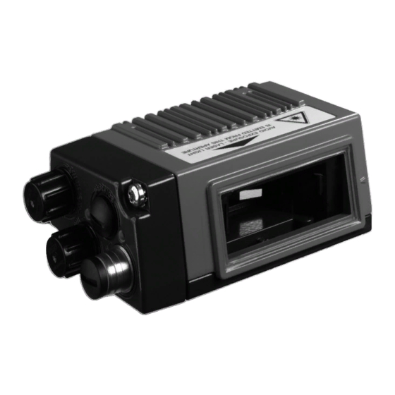
MS 3xx connector hood Display, LEDs ME 3xx connection hood and buttons Reading window Dovetail mounting 4 mounting threads Line scanner with deflecting mirror Figure 4.4: Device construction BCL 338i - Line scanner with deflecting mirror BCL 338i Leuze electronic... -
Page 33: Figure 4.5: Bcl 338I Device Construction - Oscillating-Mirror Scanner
Display, LEDs and buttons Dovetail mounting 6 mounting threads Reading window Oscillating-mirror scanner Figure 4.5: BCL 338i device construction - oscillating-mirror scanner MS 338 connector hood Connection side with system plug for connection to Mini-B type USB BCL 338i service interface... -
Page 34: Figure 4.7: Device Construction - Mk 338 Terminal Hood
Connection side with system plug for Mini-B type USB connection to service interface BCL 338i Figure 4.7: Device construction - MK 338 terminal hood ME 338 103 / ME 338 104 / ME 338 214 connection hood Connection side with... -
Page 35: Reading Techniques
• with bar codes having very short bar lengths. • when the ladder code is turned out of the vertical position (tilt angle). • when the reading distance is large. Figure 4.9: Deflection principle for the line scanner Leuze electronic BCL 338i... -
Page 36: Line Scanner With Oscillating Mirror
The oscillating mirror deflects the scan line additionally to both sides across the scan direc- tion at a randomly adjustable oscillation frequency. In this way, the BCL 338i can also scan larger areas or spaces for bar codes. The reading field height (and the scan line length useful for evaluation) depends on the reading distance due to the optical opening angle of the oscillating mirror. -
Page 37: Raster Scanner (Raster Line)
• When the bars of the bar code are perpendicular to the conveying direction (picket fence arrangement) • With bar codes with low height displacement • With very glossy bar codes Figure 4.11: Deflection principle for the raster scanner Leuze electronic BCL 338i... -
Page 38: Fieldbus Systems
From an Ethernet point of view, an EtherCAT bus segment is nothing more than a single, large Ethernet participant which sends and receives Ethernet telegrams. Within the "parti- cipant", however, there is a multitude of EtherCAT slaves rather than one single Ethernet controller. Bild 4.12: Topology example BCL 338i Leuze electronic... -
Page 39: Heating
Heating For low-temperature applications to min. -35°C (e.g. in cold storage), the bar code readers of the BCL 338i series can optionally be permanently fitted with a built-in heating and these bar code readers purchased as separate device models. autoReflAct autoReflAct stands for automatic Reflector Activation and permits an activation without additional sensors. -
Page 40: Reference Codes
The BCL 338i offers the possibility of storing one or two reference codes. It is possible to store the reference codes via the webConfig tool or via online commands. The BCL 338i can compare read bar codes with one and/or both reference codes and execute user-configurable functions depending on the comparison result. -
Page 41: Technical Data
- Switching output: 18 … 30VDC depending on supply voltage, I max. = 60mA (short-circuit proof) Switching inputs/outputs protected against polarity reversal! Operating voltage 18 … 30VDC (Class 2, protection class III) Power consumption Max. 4.5W Table 5.1: Technical data of the BCL 338i line/raster scanners without heating Leuze electronic BCL 338i... -
Page 42: Technical Data Of The Bcl
For UL applications, use is only permitted in Class 2 circuits in accordance with the NEC (National Electric Code). The BCL 338i bar code readers are designed in accordance with protection class III for sup- ply by PELV (protective extra-low voltage with reliable disconnection). -
Page 43: Oscillating-Mirror Scanner
Mechanical data Weight 350 g (without connection hood) 44 x 103 x 96 mm (without connection hood) Dimensions (H x W x D) Table 5.3: Technical data of the BCL 338i deflecting mirror scanners without heating Leuze electronic BCL 338i... -
Page 44: Heating Models Of The Bar Code Readers
Mounting location Note! The mounting location is to be selected such that the it does not expose the BCL 338i with heating directly to a cold air stream. To achieve an optimal heating effect, the BCL 338i should be mounted so that it is thermally isolated. -
Page 45: Line Scanner / Raster Scanner With Heating
-35°C … +40°C Storage temperature range -20°C … +70°C Table 5.4: Technical data of the BCL 338i line / raster scanners with heating 5.2.2 Oscillating-mirror scanner with heating Technical data same as for line scanner without heating, however with the following... -
Page 46: Line Scanner / Raster Scanner With Deflecting Mirror And Heating
Standard, M12 ready-made cable not usable (insufficient conductor cross section) Environmental data Operating temperature range -35°C … +40°C Storage temperature range -20°C … +70°C Table 5.6: Technical data of the BCL 338i deflecting mirror scanners with heating BCL 338i Leuze electronic... -
Page 47: Dimensioned Drawings
Technical data Dimensioned drawings 5.3.1 Dimensioned drawing of complete overview of the BCL 338i with MS 3xx / MK 3xx / ME 3xx Figure 5.1: Dimensioned drawing of complete overview of the BCL 338i with MS 3xx / MK 3xx / ME 3xx... -
Page 48: Dimensioned Drawing Of Line Scanner With / Without Heating
Technical data 5.3.2 Dimensioned drawing of line scanner with / without heating depth Laser beam exit Max. scanning angle Range of the laser beam Figure 5.2: Dimensioned drawing of BCL 338i S…102 line scanner BCL 338i Leuze electronic... -
Page 49: Dimensioned Drawing Of Deflecting Mirror Scanner With / Without Heating
Technical data 5.3.3 Dimensioned drawing of deflecting mirror scanner with / without heating depth Laser beam exit Max. scanning angle: 60° Range of the laser beam Figure 5.3: Dimensioned drawing of BCL 338i S…100 with deflecting mirror Leuze electronic BCL 338i... -
Page 50: Dimensioned Drawing Of Oscillating-Mirror Scanner With / Without Heating
Technical data 5.3.4 Dimensioned drawing of oscillating-mirror scanner with / without heating depth Laser beam exit Max. scanning angle Range of the laser beam Figure 5.4: Dimensioned drawing of BCL 338i O…100 oscillating-mirror scanner BCL 338i Leuze electronic... -
Page 51: Dimensioned Drawings Of Ms 3Xx / Me 3Xx / Mk 3Xx Connection Hoods
To ensure degree of protection IP 65 is fulfilled, the screws of the con- nection hood are tightened with a tightening torque of 1.4 Nm for con- necting to the BCL. Figure 5.5: Dimensioned drawing of MS 3xx connector hood / ME 3xx connection hood Leuze electronic BCL 338i... -
Page 52: Figure 5.6: Dimensioned Drawing Of Mk 3Xx Terminal Hood
To ensure degree of protection IP 65 is fulfilled, the screws of the con- nection hood are tightened with a tightening torque of 1.4 Nm for con- necting to the BCL. Figure 5.6: Dimensioned drawing of MK 3xx terminal hood BCL 338i Leuze electronic... -
Page 53: Reading Field Curves / Optical Data
Figure 5.7: The most important characteristics of a bar code The range in which the bar code can be read by the BCL 338i (the so-called reading field) depends on the quality of the printed bar code and its dimensions. -
Page 54: Raster Scanner
8 scan lines which vary depending on the reading distance from the raster aperture. Distance [mm] starting at the zero position Front scanner Deflecting mirror scanner Table 5.7: Raster line cover dependent on the distance BCL 338i Leuze electronic... -
Page 55: Reading Field Curves
The reading field curves also apply for the device models with heating. The zero position of the reading distance always refers to the front edge of the housing of the beam exit and is shown for the three housing types of the BCL 338i in Figure 5.8. Frontal beam exit BCL 3xxi S/R1…102…... -
Page 56: High Density (N) - Optics: Bcl 338I S/R1 N 102 (H)
Technical data 5.5.1 High Density (N) - optics: BCL 338i S/R1 N 102 (H) 3xxi S/R1 N 102 m = 0,127 m = 0,15 m = 0,2 -100 Reading distance [mm] Figure 5.9: "High Density" reading field curve for line scanner without deflecting mirror 5.5.2... -
Page 57: Medium Density (M) - Optics: Bcl 338I S/R1 M 102 (H)
Technical data 5.5.3 Medium Density (M) - optics: BCL 338i S/R1 M 102 (H) 3xxi S/R1 M 102 m = 0,2 m = 0,3 m = 0,5 -100 -150 Reading distance [mm] Figure 5.11: "Medium Density" reading field curve for line scanner without deflecting mirror 5.5.4... -
Page 58: Medium Density (M) - Optics: Bcl 338I O M 100 (H)
Technical data 5.5.5 Medium Density (M) - optics: BCL 338i O M 100 (H) 3xxi O M 100 m = 0,2 m = 0,3 m = 0,5 -100 -150 Reading distance [mm] Figure 5.13: "Medium Density" reading field curve for oscillating-mirror scanners... -
Page 59: Low Density (F) - Optics: Bcl 338I S/R1 F 102 (H)
Technical data 5.5.6 Low Density (F) - optics: BCL 338i S/R1 F 102 (H) 3xxi S/R1 F 102 m = 0,3 m = 0,35 m = 0,5 -100 -150 -200 Reading distance [mm] Figure 5.15: "Low Density" reading field curve for line scanner without deflecting mirror 5.5.7... -
Page 60: Low Density (F) - Optics: Bcl 338I O F 100 (H)
Technical data 5.5.8 Low Density (F) - optics: BCL 338i O F 100 (H) 3xxi O F 100 m = 0,3 m = 0,35 m = 0,5 -100 -150 -200 Reading distance [mm] Figure 5.17: "Low Density" reading field curve for oscillating-mirror scanners... -
Page 61: Ultra Low Density (L) - Optics: Bcl 338I S L 102 (H)
-250 -300 Reading distance [mm] Figure 5.19: "Ultra Low Density" reading field curve for line scanner without deflecting mir- 5.5.10 Ultra Low Density (L) - optics: BCL 338i S L 100 (H) 3xxi S/R1 L 100 m = 0,35 m = 0,5... -
Page 62: Ultra Low Density (L) - Optics: Bcl 338I O L 100 (H)
Technical data The reading field curves apply for the reading conditions stated in Table 5.8. 5.5.11 Ultra Low Density (L) - optics: BCL 338i O L 100 (H) 3xxi O L 100 m = 0,35 m = 0,5 m = 0,8... -
Page 63: Ink Jet (J) - Optics: Bcl 338I R1 J 100
Due to the shape of the optical laser spot, the CRT function may exhibit limitations (max. permissible tilt angle of ± 15°). Low-contrast bar codes that are printed with inkjet should be sent to Leuze electronic for ex- amination. Leuze electronic... -
Page 64: Installation And Mounting
Device name plate BCL 338i Save the original packaging for later storage or shipping. Note! All BCL 338i are delivered with a protective cover on the connection side which must be removed before attaching a connection hood. BCL 338i... -
Page 65: Mounting The Bcl 338I
• Via a BT 56/BT 59 mounting device in the two fastening grooves on the device bot- tom. Attention! The BCL 338i does not fulfill degree of protection IP 65 until the connection hood has been screwed on. Minimum tightening torque of the housing connecting screw of the connection hood is 1.4Nm! 6.2.1... -
Page 66: Bt 56 Mounting Device
6.2.2 BT 56 mounting device The BT 56 mounting device is available for mounting the BCL 338i using the fastening grooves. It is designed for rod mounting (Ø 16mm to 20mm). For order guide, please refer to chapter "Type overview and accessories" on page 175. -
Page 67: Figure 6.4: Mounting Example Of Bcl 338I With Bt 56
Installation and mounting Figure 6.4: Mounting example of BCL 338i with BT 56 Leuze electronic BCL 338i... -
Page 68: Bt 59 Mounting Device
For further information, see the notices in Chapter 6.3! Please refer to Chapter 5.4 for the permissible minimum and maximum distances between the BCL 338i and the labels to be read. BCL 338i... -
Page 69: Bt 300 - 1, Bt 300 W Mounting Devices
BT 300 - 1, BT 300 W mounting devices BT 300 W mounting bracket Mounting bracket for rod mounting Ø 12 … 16mm BT 300 - 1 all dimensions in mm Figure 6.6: BT 300 - 1, BT 300 W mounting devices Leuze electronic BCL 338i... -
Page 70: Device Arrangement
In each case, the housing base is the black area in Figure 6.2. The best read results are obtained when: • The BCL 338i is mounted in such a way that the scanning beam is incident on the bar code at an angle of inclination greater than ±10° … 15° to vertical. -
Page 71: Avoiding Total Reflection - Line Scanner
6.3.3 Avoiding total reflection – deflecting mirror scanner For the BCL 338i with deflecting mirror, the laser beam exits at an angle of 105° to the rear housing wall. An angle of incidence of 15° of the laser to the label has already been integrated in the deflecting mirror so that the BCL 338i can be installed parallel to the bar code (rear housing wall). -
Page 72: Avoiding Total Reflection - Oscillating-Mirror Scanner
For the BCL 338i with oscillating mirror, the swivel range of ±20° (±12° for devices with heating) is to be taken into account. This means that in order to be on the safe side and to avoid total reflection, the BCL 338i with oscillating mirror must be inclined upward or downward 20° … 30°! -
Page 73: Devices With Integrated Heating
• Mount in such a way that the device is protected from draft and wind; mount additional shields if necessary. Note! When installing the BCL 338i in a protective housing, it must be ensured that the scanning beam can exit the protective housing without obstruction. 6.3.7... -
Page 74: Cleaning
Installation and mounting Cleaning Clean the glass window of the BCL 338i with a soft cloth after mounting. Remove all packaging remains, e.g. carton fibers or styrofoam balls. In doing so, avoid leaving fin- gerprints on the front screen of the BCL 338i. -
Page 75: Electrical Connection
Additional connection accessories can be found in Chapter 14. Attention! The BCL 338i does not fulfill degree of protection IP 65 until the connection hood has been screwed on. Minimum tightening torque of the housing connecting screw of the connection hood is 1.4Nm! -
Page 76: Safety Notices For The Electrical Connection
Do not open the device yourself under any circumstances! There is otherwise a risk of un- controlled emission of laser radiation from the device. The housing of the BCL 338i contains no parts that need to be adjusted or maintained by the user. -
Page 77: Bcl 338I Electrical Connection
The MS 338 connector hood features three M12 connector plugs and a Mini-B type USB socket as a service interface. Parameter memory is integrated into the MS 338 which tempo- rarily stores the settings of the BCL 338i in the case of replacement and transmits them to a new device. -
Page 78: Me 338 103 Connection Hood With M12 Connection Cables
Electrical connection Note! In the case of EtherCAT line topology, the network is interrupted when the BCL 338i is re- moved from the MS 338. Note! Dimensioned drawing on see chapter 5.3.5 "Dimensioned drawings of MS 3xx / ME 3xx / MK 3xx connection hoods"... - Page 79 ME 338 103. In the integrated parameter memory, both the settings and the network address are saved and transmitted to a new device. Note! In the case of EtherCAT line topology, the network is interrupted when the BCL 338i is re- moved from the ME 338 103. Note! Dimensioned drawing on see chapter 5.3.5 "Dimensioned drawings of MS 3xx / ME 3xx /...
-
Page 80: Me 338 104 Connection Hood With M8/M12 Connection Cables
M8 connectors and a Mini-B type USB socket as service interface. Parameter memory is integrated into the ME 338 104 which temporarily stores the settings of the BCL 338i in the case of replacement and transmits them to a new device. Connection hood... -
Page 81: Me 338 214 Connection Hood With M8/M12/Rj45 Connection Cables
Electrical connection Note! In the case of EtherCAT line topology, the network is interrupted when the BCL 338i is re- moved from the ME 338 104. Note! Dimensioned drawing on see chapter 5.3.5 "Dimensioned drawings of MS 3xx / ME 3xx / MK 3xx connection hoods"... -
Page 82: Mk 338 Terminal Hood With Spring-Cage Terminals
ME 338 214. In the integrated parameter memory, both the settings and the network address are saved and transmitted to a new device. Note! In the case of EtherCAT line topology, the network is interrupted when the BCL 338i is re- moved from the ME 338 214. Note! Dimensioned drawing on see chapter 5.3.5 "Dimensioned drawings of MS 3xx / ME 3xx /... -
Page 83: Figure 7.7: Cable Fabrication For Mk 338 Terminal Hood
MK 338. In the integrated parameter memory, both the settings and the network address are saved and transmitted to a new device. Note! In the case of EtherCAT line topology, the network is interrupted when the BCL 338i is re- moved from the MK 338. Cable fabrication and shielding connection Remove approx. -
Page 84: Detailed Description Of The Connections
Connecting the functional earth FE Ensure that the functional earth (FE) is connected correctly. Unimpaired operation is only guaranteed when the functional earth is connected properly. All electrical disturbances (EMC couplings) are discharged via the functional earth connection. BCL 338i Leuze electronic... -
Page 85: Figure 7.1: Switching Input Connection Diagram Swio_1 And Swio_2
The bar code readers of the BCL 300i series are equipped with two freely programmable, opto-decoupled switching inputs and outputs, SWIO_1 and SWIO_2. The switching inputs can be used to activate various internal functions of the BCL 338i (decoding, autoConfig, …). The switching outputs can be used to signal the state of the BCL 338i and to implement external functions independent of the superior control. -
Page 86: Sensor - Direct Connection Of An External Sensor (Me 338 Xx4 Only)
Attention! Each configured switching output is short-circuit proof! Do not load the respective switching output of the BCL 338i with more than 60mA at +18 … +30VDC in normal operation! Note! Both switching inputs/outputs SWIO_1 and SWIO_2 are configured by default in such a way that: •... -
Page 87: Service - Usb Interface (Mini-B Type)
Use the Leuze-specific USB service cable (see chapter 14 "Type overview and acces- sories") for the connection and use a service PC to configure. Note! IP 65 is achieved only if the connectors and caps are screwed into place. Leuze electronic BCL 338i... -
Page 88: Host / Bus In For Bcl 338I
Pin assignment HOST / BUS IN for BCL 338i For the host connection of the BCL 338i, the "KSS ET-M12-4A-RJ45-A-P7-…" ready- made cables are preferred, see Table 14.9 "Bus connection cables for the BCL 338i" on page 180. BCL 338i... -
Page 89: Figure 7.1
HOST / BUS IN cable assignments on RJ-45 Note for connecting the EtherCAT interface! Ensure adequate shielding. The entire interconnection cable must be shielded and earthed. The RD+/RD- and TD+/TD- wires must be stranded in pairs. Use CAT 5 cables for the connection. Leuze electronic BCL 338i... -
Page 90: Bus Out For The Bcl 338I
Ethernet interface. The use of this interface drastically reduces the cabling requirements, as only the first BCL 338i requires a direct connection to the switch, via which it can communicate with the host. All other BCL 338i are connected in series to the first BCL 338i, see Figure 7.3. -
Page 91: Ethercat Topologies
Electrical connection Note! For the BCL 338i as stand-alone device or as the last participant in a linear topology, termi- nation on the BUS OUT socket is not mandatory! EtherCAT topologies EtherCAT permits a multitude of topologies such as line, tree, ring, star and combinations of these. -
Page 92: Ethercat Wiring
A Cat. 5 Ethernet cable should be used for wiring. Connection hood "ME 338 214" is available for the direct connection to the BCL 338i. It is equipped with 2 connection cables with RJ45 socket into which the standard network cables can be plugged. -
Page 93: Cable Lengths And Shielding
BCL to the EtherCAT 100Base-TX Twisted Pair required last BCL (min. Cat. 5) BCL – power Not necessary supply unit 10 m Not necessary Switching input 10 m Not necessary Switching output Table 7.6: Cable lengths and shielding Leuze electronic BCL 338i... -
Page 94: Display Elements And Display
Display elements and display Display elements and display The BCL 338i is available optionally with display, 2 control buttons and LEDs or with only 2 LEDs as display elements. BCL 338i LED indicators 2 LEDs Figure 8.1: BCL 338i - LED indicators 2 multicolor LEDs are used as the primary display instrument. - Page 95 - No data on the host interface red, flashing Warning set - Bar code reading possible - Self test runs for 0.25s after power up - Temporary operating fault red, continuous light Device error - No bar code reading possible Leuze electronic BCL 338i...
- Page 96 Local error, e.g., synchronization error red, flashing, double flash Process Data Watchdog Timeout or EtherCAT Watchdog Timeout or Sync Manager Watchdog Timeout red, continuous light Bus error, no communication established to master BCL 338i Leuze electronic...
-
Page 97: Ms 338/Me 338
(split, two-colored): ACT1 / LINK1 ME 338… Ethernet 0 LED Ethernet 1 LED (split, two-colored): (split, two-colored): ACT0 / LINK0 ACT1 / LINK1 2 LEDs MS 338 Figure 8.2: MS 338/ME 338…/MK 338 - LED indicators Leuze electronic BCL 338i... - Page 98 LEDs each in the MS 338, ME 338… and MK 338: ACT0 / LINK0 LED green, continuous light EtherCAT connected (LINK) yellow, flashing Data communication (ACT) ACT1 / LINK1 LED green, continuous light EtherCAT connected (LINK) yellow, flashing Data communication (ACT) BCL 338i Leuze electronic...
-
Page 99: Bcl 338I Display
BCL 338i - Display Note! The function of the LEDs is identical for the devices with and without display. The optional display of the BCL 338i has the following features: • Monochromatic with background lighting (blue/white) • Double line, 128 x 32 pixels •... - Page 100 • 1st line: alignment mode display function • 2nd line: decoding quality in percent, e.g. 73% • 1st line: version display function Version • 2nd line: software and hardware version of the SW: xxxxx HW: xxx device BCL 338i Leuze electronic...
-
Page 101: Leuze Webconfig Tool
• Chinese Connecting the SERVICE USB interface The connection to the SERVICE USB interface of the BCL 338i is established via the PC-side USB interface using a standard USB cable with 1 type A connector and a Mini-B type connector. -
Page 102: Installing The Required Software
If you have already installed a USB driver for a BCL 5xxi on your computer, you don't have to install the USB driver for the BCL 338i. In this case, you can also start the webConfig tool of the BCL 338i by double-clicking on the BCL 5xxi icon. -
Page 103: Starting The Webconfig Tool
If the webConfig communication (tunneled in EoE) between the engineering station and the BCL 338i is very slow, the cycle time of the PLC may have to be reduced (e.g. a cycle time of 0.4 … 0.5 ms instead of 1 ms) and the web browser be restarted. -
Page 104: Short Description Of The Webconfig Tool
Short description of the webConfig tool The webConfig tool has 5 main menus: Home • with information on the connected BCL 338i as well as on installation. This informa- tion corresponds to the information in this handbook. Alignment • for manually starting read processes and for aligning the bar code reader. The results of the read processes are displayed immediately. -
Page 105: Oscillating Mirror
Leuze webConfig tool Note! The webConfig tool is completely contained in the firmware of the BCL 338i. Depending on firmware version, the module overview may vary from that shown above. The individual modules and their relationships to one another are graphically displayed in the module overview. -
Page 106: Commissioning And Configuration
Via the webConfig tool The most convenient way to configure the BCL 338i is via the webConfig tool. To use the webConfig tool, you need to establish a USB connection between the BCL 338i and a PC/ laptop. -
Page 107: Additional Settings For The Bcl 338I
• Control of the switching outputs 10.3.1 Decoding and processing the read data The BCL 338i offers the following options: • Setting the number of labels to be decoded for each reading gate (0 … 64). This is done via the Max. no. of labels parameter. - Page 108 Data processing via the webConfig tool In the Data and Output submenus of the Configuration main menu, the webConfig tool provides extensive data processing options to adapt the functionality of the BCL 338i to the specific reading task: • Data filtering and segmentation in the Data submenu: •...
-
Page 109: 10.3.2 Control Of The Decoding
• Start the automatic code type configuration (AutoConfig) Connect the required control devices (photoelectric sensor, proximity switch, etc.) as described in Chapter 7 to the BCL 338i. Configure the connected switching inputs according to your requirements. To do this, first... -
Page 110: 10.3.3 Control Of The Switching Outputs
Commissioning and configuration 10.3.3 Control of the switching outputs By using the switching inputs/outputs of the BCL 338i, external event-controlled functions can be implemented without assistance from the superior process control. For this purpose, the respective connection at the SW IN/OUT and POWER interfaces must be configured as a switching output. -
Page 111: Transmitting Configuration Data
• Storage in a file and transfer using the webConfig tool 10.4.1 Via the webConfig tool With the webConfig tool, you can store entire configurations of the BCL 338i on data carriers and transfer them from these to the BCL 338i. -
Page 112: Bcl 338I In The Ethercat System
If the webConfig communication (tunneled in EoE) between the engineering station and the BCL 338i is very slow, the cycle time of the PLC may have to be reduced (e.g. a cycle time of 0.4 … 0.5 ms instead of 1 ms) and the web browser be restarted. -
Page 113: Canopen Over Ethercat - Coe
Note! Second Station Address (Configured Station Alias) With the BCL 338i, the Second Station Address is set by the EtherCAT master. This address is typically assigned in the project engineering software (e.g., TwinCAT). No provision is made for setting via the webConfig tool. The Second Station Address can, however, be dis- played in webConfig. -
Page 114: Starting The Bcl 338I In The Ethercat System
The master produces output data, but input data is not considered. This means the BCL 338i does not return output data (= PLC input data) in SAFEOP. The bar code reader processes input process data (= PLC output data). Mailbox communication via CoE services is possible. -
Page 115: Device Profile
The ESI file contains all objects with index, sub-index, name, data type, default value, minimum and maximum, and access possibilities. That means the ESI file describes the entire functionality of the BCL 338i, and it is possible to adjust the communication of the bar code reader with the control. -
Page 116: Figure 11.1: Configuration Options
The ESI file has the name BCL338i.xml and is available for download on the Leuze home page. Vendor ID for the BCL 338i The Vendor ID assigned by Leuze electronic for the BCL 338i is 121 = 289 BCL 338i... -
Page 117: 11.4.2 Object Directory Overview
BCL 338i in the EtherCAT system 11.4.2 Object directory overview The object directory of the BCL 338i is the compilation of all process data and parameters of the bar code reader. The following overview table shows all objects supported by the BCL 338i. -
Page 118: 11.4.3 Communication Objects
BCL 338i in the EtherCAT system 11.4.3 Communication objects 11.4.3.1 Object 1000 Device type The object describes the device type. Index Sub- Name Data type Access Value range Comment index (hex) (hex) Minimum Maximum Default Not a standardized 1000 Device type... -
Page 119: 11.4.3.5 Object 1018
Example (is incre- mented with each Revision new software ver- sion) Serial Example number The vendor ID of Leuze electronic GmbH + Co. KG is 289 (121 The product code of the BCL 338i is 5 Leuze electronic BCL 338i... -
Page 120: 11.4.3.6 Objects 1600
This mapping is identical for all Receive PDO mapping objects and is, thus, present in every 1600 … 1607 object. From the perspective of the control, this is the output data that is sent from the master to the BCL 338i. (see Chapter 11.4.3.7 to Chapter 11.4.3.14). Index Sub-... -
Page 121: Object 1600 1St Receive Pdo Mapping Rxpdo1 (Submission Data, 8 Bytes)
Receive PDO Mapping RxPDO1 (Submission data, 8 bytes) This object defines the first Receive PDO mapping with the output data (data that is sent from the master to the BCL 338i). The mapping object references device-specific object 0x2100 Submission data 1 (see Chapter 11.4.4.3). -
Page 122: Object 1602 3Rd Receive Pdo Mapping Rxpdo3 (Submission Data, 32 Bytes)
Receive PDO Mapping RxPDO3 (Submission data, 32 bytes) This object defines the third Receive PDO mapping with the output data (data that is sent from the master to the BCL 338i). The mapping object references device-specific object 0x2102 Submission data 3 (see Chapter 11.4.4.3). -
Page 123: Object 1603 4Th Receive Pdo Mapping Rxpdo4 (Submission Data, 48 Bytes)
Receive PDO Mapping RxPDO4 (Submission data, 48 bytes) This object defines the fourth Receive PDO mapping with the output data (data that is sent from the master to the BCL 338i). The mapping object references device-specific object 0x2103 Submission data 4 (see Chapter 11.4.4.3). -
Page 124: Object 1604 5Th Receive Pdo Mapping Rxpdo5 (Submission Data, 64 Bytes)
Receive PDO Mapping RxPDO5 (Submission data, 64 bytes) This object defines the fifth Receive PDO mapping with the output data (data that is sent from the master to the BCL 338i). The mapping object references device-specific object 0x2104 Submission data 5 (see Chapter 11.4.4.3). -
Page 125: Object 1605 6Th Receive Pdo Mapping Rxpdo6 (Submission Data, 96 Bytes)
Receive PDO Mapping RxPDO6 (Submission data, 96 bytes) This object defines the sixth Receive PDO mapping with the output data (data that is sent from the master to the BCL 338i). The mapping object references device-specific object 0x2105 Submission data 6 (see Chapter 11.4.4.3). -
Page 126: 11.4.3.13 Object 1606
Receive PDO Mapping RxPDO7 (Submission data, 128 bytes) This object defines the seventh Receive PDO mapping with the output data (data that is sent from the master to the BCL 338i). The mapping object references device-specific object 0x2106 Submission data 7 (see Chapter 11.4.4.3). -
Page 127: Object 1607 8Th Receive Pdo Mapping Rxpdo8 (Submission Data, 252 Bytes)
Receive PDO Mapping RxPDO8 (Submission data, 252 bytes) This object defines the eighth Receive PDO mapping with the output data (data that is sent from the master to the BCL 338i). The mapping object references device-specific object 0x2107 Submission data 8 (see Chapter 11.4.4.3). -
Page 128: Objects 1A00 ... 1A07 - General Mapping
This mapping is identical for all Transmit PDO mapping objects and is, thus, present in every 1A00 … 1A07 object. From the perspective of the control, this is the input data that is sent from the BCL 338i to the master. (see Chapter 11.4.3.16 to Chapter 11.4.3.23). Index Sub-... - Page 129 BCL 338i in the EtherCAT system Index Sub- Name Data type Access Value range Comment index (hex) (hex) Minimum Maximum Default Object 2150, Sub-index14 0x08035021 sub-index 03, "Error code" Object 2450, Sub-index15 0x08015024 sub-index 01, "Device status" Leuze electronic BCL 338i...
-
Page 130: Object 1A00 1St Transmit Pdo Mapping Txpdo1 (Result Data, 8 Bytes)
Transmit PDO Mapping TxPDO2 (Result data, 16 bytes) This object defines the second Transmit PDO mapping with the result data (input data that is sent from the BCL 338i to the master). The mapping object references device-specific object 0x2001 Result data 2 (see Chapter 11.4.4.1). -
Page 131: Object 1A02 3Rd Transmit Pdo Mapping Txpdo3 (Result Data, 32 Bytes)
Transmit PDO Mapping TxPDO3 (Result data, 32 bytes) This object defines the third Transmit PDO mapping with the result data (input data that is sent from the BCL 338i to the master). The mapping object references device-specific object 0x2002 Result data 3 (see Chapter 11.4.4.1). -
Page 132: Object 1A03 4Th Transmit Pdo Mapping Txpdo4 (Result Data, 48 Bytes)
Transmit PDO Mapping TxPDO4 (Result data, 48 bytes) This object defines the fourth Transmit PDO mapping with the result data (input data that is sent from the BCL 338i to the master). The mapping object references device-specific object 0x2003 Result data 4 (see Chapter 11.4.4.1). -
Page 133: Object 1A04 5Th Transmit Pdo Mapping Txpdo5 (Result Data, 64 Bytes)
Transmit PDO Mapping TxPDO5 (Result data, 64 bytes) This object defines the fifth Transmit PDO mapping with the result data (input data that is sent from the BCL 338i to the master). The mapping object references device-specific object 0x2004 Result data 5 (see Chapter 11.4.4.1). -
Page 134: Object 1A05 6Th Transmit Pdo Mapping Txpdo6 (Result Data, 96 Bytes)
Transmit PDO Mapping TxPDO6 (Result data, 96 bytes) This object defines the sixth Transmit PDO mapping with the result data (input data that is sent from the BCL 338i to the master). The mapping object references device-specific object 0x2005 Result data 6 (see Chapter 11.4.4.1). -
Page 135: Object 1A06 7Th Transmit Pdo Mapping Txpdo7 (Result Data, 128 Bytes)
Transmit PDO Mapping TxPDO7 (Result data, 128 bytes) This object defines the seventh Transmit PDO mapping with the result data (input data that is sent from the BCL 338i to the master). The mapping object references device-specific object 0x2006 Result data 7 (see Chapter 11.4.4.1). -
Page 136: Object 1A07 8Th Transmit Pdo Mapping Txpdo8 (Result Data, 252 Bytes)
Transmit PDO Mapping TxPDO8 (Result data, 252 bytes) This object defines the eighth Transmit PDO mapping with the result data (input data that is sent from the BCL 338i to the master). The mapping object references device-specific object 0x2007 Result data 8 (see Chapter 11.4.4.1). -
Page 137: 11.4.3.24 Object 1C00
BCL 338i in the EtherCAT system 11.4.3.24 Object 1C00 Sync Manager Communication Type This object defines which Sync Manager realizes which data channel. The BCL 338i is configured as follows. Index Sub- Name Data type Access Value range Comment index... -
Page 138: 11.4.3.25 Object 1C12
BCL 338i in the EtherCAT system 11.4.3.25 Object 1C12 Sync Manager 2 PDO Assignment This object defines the Receive PDO object RxPDO1 … RxPDO8 assigned to Sync Manager 2. Index Sub- Name Data type Access Value range Comment index (hex) -
Page 139: 11.4.4 Device-Specific Objects
1600 to 1607 These objects contain the result data (read results of the BCL 338i). The result data is dependent on the selected result formatting. This can be selected and configured with the webConfig tool. -
Page 140: 11.4.4.2 Object 0X2050
Code data or command response The status bit makes it easier to distinguish whether the result data is a formated read result (formatted code content) or the response from the command interpreter of the BCL 338i. Formatted read result (formatted code content) - Page 141 New result data 1 -> 0 New result data Waiting on master response This status bit represents the state of the internal control of the BCL 338i. Operative state Control waiting for acknowledgment from the master Result data length This sub-object contains the data length of the actual result information.
-
Page 142: Objects 0X2100 To 0X2107 Submission Data
It is, however, possible to configure the BCL 338i using 'PT' sequences (see chapter 12.1.4 "Online commands for the parameter set operations") from within the control. You can obtain detailed information on this topic from Leuze electronic on request. -
Page 143: Figure 11.2: Sequence Diagram For Data Acceptance/Data Rejection
Reaction of the BCL 338i on successful data acceptance: Toggle bit Data transfer = 0 -> 1 or 1 -> 0, Failed data acceptance from the perspective of the BCL 338i (object index 2150 Initial situation: Toggle bit Data transfer = 0 or 1, Toggle bit Data rejection = 0 or 1, Toggle bit New submission = 0 ->... -
Page 144: 11.4.4.4 Object 0X2150
No. of sub-indexes Specifies the number of sub-indexes. Data transfer (toggle) The toggle bit shows that the BCL 338i has accepted the data or the data fragment (also see Data rejection (toggle)). 0 -> 1 Data has been accepted 1 ->... - Page 145 BCL 338i in the EtherCAT system ferred from the control, the number of remaining fragments or the fragment size. New submission (toggle) This toggle bit indicates whether new output data is present. 0 -> 1 New output data 1 -> 0...
-
Page 146: Object 0X2200 Activation
BCL 338i in the EtherCAT system 11.4.4.5 Object 0x2200 Activation The object 0x2200 defines the control signals for activating the device as well as the signals for the control of the result output. It is possible to select between standard data output oper- ation and handshake operation. - Page 147 BCL 338i in the EtherCAT system Activation signal Activation signal for activating the device (opening of the reading gate). This sub-object is edge-triggered. 0 -> 1 Activation (opening of the reading gate) 1 -> 0 Deactivation (closing of the reading gate)
-
Page 148: Object 0X2300 Fragmented Result
Fragmented result The object 0x2300 defines the output of fragmented results (direction: from the BCL 338i to control). To occupy few I/O data, the results may be split into several fragments with this object. The fragments can then be transmitted one after another with a handshake. - Page 149 BCL 338i in the EtherCAT system Fragment length The parameter defines the maximum length (in bytes) of the result information per fragment. Permissible value range: 1 … 255 bytes Note! This setting can only be performed via CoE (startup parameter) in PreOp ESM state.
-
Page 150: Object 0X2400 Fragmented Submission
(direction: from control to the BCL 338i) on the command interpreter in the device. To occupy few I/O data, the output data may be split into several fragments with this object. The fragments can then be trans- mitted one after another with a handshake. - Page 151 BCL 338i in the EtherCAT system Fragment no. This sub-object contains the current fragment number of the fragmented output data. Permissible value range: 0 … 255 bytes Remaining no. of fragments This sub-object contains the number of fragments which still have to be transmitted for a complete output.
-
Page 152: 11.4.4.8 Object 0X2450
’H’ command) if the bit changes from 0 to 1. Activation of this bit triggers a restart of all electronics including the communication stack. Upon completion of the restart, this bit is reset to 0 by the BCL 338i. 0 -> 1... -
Page 153: Communication Examples
BCL 338i in the EtherCAT system Standby This control bit activates the standby function of the bar code reader. Standby off Standby on Note! During a data reset (see object 0x2200 sub-index 05 ), the status data of this object is not deleted 11.5... -
Page 154: Figure 11.3: Sequence Diagram For Reading A Bar Code
BCL 338i in the EtherCAT system 14-digit bar code: "ABCDE123456789" EtherCAT Master BCL338i Object 0x2200 : Activation Activation Data = "ABCD", New result (toggle) = 1 Read result Code data or command response = 0, Object 0x2000 : Result data 1... -
Page 155: 11.5.2 Application Case: Transmitting 'Pt' Sequences
11.5.2 Application case: Transmitting 'PT' sequences With the help of an output data object, commands are transmitted to the command inter- preter of the BCL 338i. The control receives the responses from the BCL 338i via a result object. Specifically, the following 'PT' sequence is to be sent to the BCL 338i:... -
Page 156: Online Commands
Online commands can be used to send commands directly to the device for control and configuration. For this purpose, the BCL 338i must be connected to a host- or service computer via the interface. The commands described can be sent either via the host or the service interface. -
Page 157: 12.1.1 General Online Commands
Requests device version information Parameter 'BCL 338i SM 100 V 1.1.0 2017-01-15' The first line contains the device type of the BCL 338i, followed by the Acknowledgment device version number and version date. (The data which is actually displayed may vary from the values given here.) Note! This command returns the major release number of the software packet. - Page 158 Code 93 ’13’ GS1 DataBar OMNIDIRECTIONAL ’14’ GS1 DataBar LIMITED ’15’ GS1 DataBar EXPANDED Number of digits of the read code Contents of the decoded label. A appears if the label was zzzzzz: not correctly read. BCL 338i Leuze electronic...
- Page 159 ’CA’ Activates or deactivates the ’autoConfig’ function. Certain label reading Description parameters are programmed automatically in the setup by the labels which the BCL 338i reads while the ’autoConfig’ function is active. ’+’ Activates ’autoConfig’ ’/’ Rejects the last code read Parameter ’-’...
- Page 160 Alignment mode Command ’JP’ This command simplifies mounting and alignment of the BCL 338i. After activating the function with ’JP+’, the BCL 338i continuously supplies sta- tus information to the serial interfaces. With this online command, the scanner is set to terminate the decoding after 100 successfully decoded labels and output the status information.
- Page 161 ’RS’ This command can be used to define a new reference code in the BCL 338i by means of direct input via the serial interface. The data is Description saved in the parameter set according to your input under reference code 1 through 2 and stored in the working buffer for direct further pro- cessing.
- Page 162 Parameter no_of_labels ’-’ Ends the teach event The BCL 338i first responds with the command ’RS’ and correspond- ing status (see command ’RS’). After a bar code has been read, it sends the result in the following format: ’RCyvxxzzzzz’...
- Page 163 Online commands Reading a reference code Command ’RR’ The command reads out the reference code defined in the BCL 338i. If Description no parameters are specified, all defined codes are output. <Reference code number> Parameter ’1’ … ’2’ value range of reference codes 1 to 2 If no reference codes are defined, the BCL 338i responds with the ’RS’...
-
Page 164: 12.1.2 Online Commands For System Control
The command activates decoding. This command can be used to deactivate the reading gate. Following deactivation, the read result is Description output. Because the reading gate was manually deactivated and, thus, no GoodRead criterion was met, a NoRead is output. Parameter Acknowledgment None BCL 338i Leuze electronic... -
Page 165: 12.1.3 Online Commands For Configuring The Switching Inputs/Outputs
(e.g., inverted logic and a state of High corre- sponds to a voltage of 0V at the switching output). Parameter ’OA?’ ’OA S1=<a>;S2=<a>’ <a> State of the switching outputs Acknowledg- ’0’ ment ’1’ High ’I’ Configuration as switching input ’P’ Passive configuration Leuze electronic BCL 338i... - Page 166 The logic state is output, i.e., an inverted logic is taken into account (e.g., inverted logic and a state of High corresponds to a voltage of 0V at the switching output). ’OD<a>’ Parameter <a> Selected switching output [1, 2], unit (dimensionless) Acknowledg- None ment BCL 338i Leuze electronic...
- Page 167 ’OF [S1=<a>][;S2=<a>]’ <a> Function of the switching input/ output, unit [dimension- less] Parameter ’I Switching input ’O’ Switching output ’P’ Passive ’OF=<bb>’ <bb> Status acknowledgment Acknowledg- ’00’ ment ’01’ Syntax error ’02’ Parameter error ’03’ Other error Leuze electronic BCL 338i...
-
Page 168: 12.1.4 Online Commands For The Parameter Set Operations
Copying the default parameters to the permanent memory and to the main memory ’PS=<aa>’ <aa> Status acknowledgment, unit [dimensionless] ’00’ ’01’ Syntax error Acknowledgment ’02’ Impermissible command length ’03’ Reserved ’04’ Reserved ’05’ Reserved ’06’ Impermissible combination, source type - target type BCL 338i Leuze electronic... - Page 169 Requesting parameter data set from BCL 338i Command ’PR’ The parameters of the BCL 338i are grouped together in a parameter set and permanently stored in memory. There is one parameter set in permanent memory and one operating parameter set in volatile mem- Description ory;...
- Page 170 Impermissible number of data requested ’06’ Requested data does not (any longer) fit in the transmis- sion buffer ’07’ Impermissible address value ’08’ Read access after end of data set ’09’ Impermissible QPF data set type BCL 338i Leuze electronic...
- Page 171 Relative address of the data within the data set ’aaaa’ Four-digit, unit [dimensionless] <P.value> Parameter value of the -bb- parameter stored at this address. The parameter set data is converted from HEX format to a 2-byte-ASCII format for transfer. Leuze electronic BCL 338i...
- Page 172 Online commands Command ’PD’ ’PS=<aa>’ <aa> Status acknowledgment, unit [dimensionless] ’0’ No difference Acknowledgment ’1’ Syntax error negative ’2’ Impermissible command length ’6’ Impermissible combination, parameter set 1 and param- eter set 2 ’8’ Invalid parameter set BCL 338i Leuze electronic...
- Page 173 Writing parameter set Command ’PT’ The parameters of the BCL 338i are grouped together in a parameter set and permanently stored in memory. There is one parameter set in permanent memory and one operating parameter set in volatile mem- Description ory;...
- Page 174 Impermissible command length ’03’ Impermissible value for checksum type Acknowledgment ’04’ Invalid check sum received ’05’ Impermissible data length ’06’ Invalid data (parameter limits violated) ’07’ Invalid start address ’08’ Invalid parameter set ’09’ Invalid parameter set type BCL 338i Leuze electronic...
-
Page 175: Diagnostics And Troubleshooting
Possible error causes Measures • Incorrect interconnection cable Check interconnection cable No communication via • Connected BCL 338i is not Install USB driver USB service interface recognized • Incorrect wiring Check wiring • In particular, check wire shielding •... - Page 176 Customer data (please complete) Device type: Company: Contact person/department: Phone (direct dial): Fax: Street / no.: ZIP code / City: Country: Leuze Service fax number: +49 7021 573 - 199 BCL 338i Leuze electronic...
-
Page 177: Type Overview And Accessories
Line scanner (raster) ciple Oscillating-mirror scanner integrated fieldbus technology RS 232/RS 422 (stand-alone) RS 485 (multiNet slave) PROFIBUS DP Interface ETHERNET TCP/IP, UDP EtherCAT PROFINET-IO RT EtherNet/IP BCL Bar code reader Tabelle 14.1: BCL 338i part number code Leuze electronic BCL 338i... -
Page 178: Bcl 338I Type Overview
50135028 BCL 338i S L 102 D with L optics and display 50135029 BCL 338i S N 102 D H with N optics, display and heating 50135030 BCL 338i S M 102 D H with M optics, display and heating... -
Page 179: Accessories - Connection Hoods
ME 338 103 Connection hood for BCL 338i, 3 x M12 50134929 ME 338 104 Connection hood for BCL 338i, 3 x M12, 1 x M8 50134927 ME 338 214 Connection hood for BCL 338i, 1x M12, 1x M8, 2x RJ45 50134928 Table 14.3:... -
Page 180: Accessory - Ready-Made Cables For Voltage Supply
M12 socket for PWR, axial plug outlet, open cable end, cable KD U-M12-5A-V1-100 50132080 length 10m, not shielded Table 14.8: PWR cable for the BCL 338i 14.9 Accessory - Ready-made cables for bus connection 14.9.1 General information • Cable for connecting to EtherCAT using M12 connector •... -
Page 181: 14.9.2 Contact Assignment Of M12 Ethercat Connection Cable
In motion: -25°C ... +60°C (when used with drag chains) Material Cable sheath: PUR (green), wire insulation: PE foam, Free of halogens, silicone and PVC Bending radius > 65mm, suitable for drag chains Bending cycles > 10 , perm. acceleration < 5m/s Leuze electronic BCL 338i... -
Page 182: 14.9.4 Order Codes For M12 Ethercat Connection Cable
Cable length 5m, cable 1:1, not crossed 50137078 KSS ET-M12-4A-M12-4A-P7-100 Cable length 10m, cable 1:1, not crossed 50137079 KSS ET-M12-4A-M12-4A-P7-150 Cable length 15m, cable 1:1, not crossed 50137080 Table 14.9: Bus connection cables for the BCL 338i BCL 338i Leuze electronic... -
Page 183: Maintenance
Maintenance 15.1 General maintenance information Usually, the BCL 338i bar code reader does not require any maintenance by the operator. Cleaning Clean glass surface with a damp sponge soaked in commercial cleaning detergent. Then rub it with a soft, clean, dry cloth. -
Page 184: Appendix
Appendix Appendix 16.1 Declarations of Conformity Figure 16.1: BCL 338i Declaration of Conformity BCL 338i Leuze electronic... -
Page 185: Figure 16.2: Connection Hood / Connection Unit Declaration Of Conformity
Appendix Figure 16.2: Connection hood / connection unit declaration of conformity Leuze electronic BCL 338i... -
Page 186: Ascii Character Set
End of data transmission block CANCEL Invalid END OF MEDIUM End of medium SUBSTITUTE Substitution ESCAPE Escape FILE SEPARATOR File separator GROUP SEPARATOR Group separator RECORD SEPARATOR Record separator UNIT SEPARATOR Unit separator SPACE Space EXCLAMATION POINT Exclamation point BCL 338i Leuze electronic... - Page 187 Number Number Number Number COLON Colon SEMICOLON Semicolon < LESS THAN Less than EQUALS Equals > GREATER THAN Greater than QUESTION MARK Question mark COMMERCIAL AT Commercial AT Capital letter Capital letter Capital letter Capital letter Leuze electronic BCL 338i...
- Page 188 Reverse slant CLOSING BRACKET Closing bracket CIRCUMFLEX Circumflex UNDERSCORE Underscore ‘ GRAVE ACCENT Grave accent Lower case letter Lower case letter Lower case letter Lower case letter Lower case letter Lower case letter Lower case letter BCL 338i Leuze electronic...
- Page 189 Lower case letter Lower case letter Lower case letter Lower case letter Lower case letter Lower case letter Lower case letter OPENING BRACE Opening brace VERTICAL LINE Vertical line CLOSING BRACE Closing brace TILDE Tilde DELETE (RUBOUT) Delete Leuze electronic BCL 338i...
-
Page 190: Bar Code Samples
Modul 0,3 Code type 10: EAN 13 Add-on SC 0 77889 abcde Code type 08: EAN 128 1 122334 455666 Modul 0,3 Code type 13: GS1 DataBar OMNIDIRECTIONAL leuze Figure 16.3: Bar code sample labels (module 0.3) BCL 338i Leuze electronic... -
Page 191: Module 0.5
Modul 0,5 A151617A 9876 5430 Code 128 Modul 0,5 Code type 10: EAN 13 Add-on SC 2 44332 fghij Code type 08: EAN 128 Modul 0,5 0 099887 766550 LEUZE Figure 16.4:Bar code sample labels (module 0.5) Leuze electronic BCL 338i...
Need help?
Do you have a question about the BCL 338i and is the answer not in the manual?
Questions and answers