Sign In
Upload
Download
Table of Contents
Contents
Add to my manuals
Delete from my manuals
Share
URL of this page:
HTML Link:
Bookmark this page
Add
Manual will be automatically added to "My Manuals"
Print this page
×
Bookmark added
×
Added to my manuals
Manuals
Brands
HIMA Manuals
Controller
F3 DIO 16/8 01
Manual
HIMA F3 DIO 16/8 01 Manual
Safety-related controller
Hide thumbs
1
2
Table Of Contents
3
4
5
6
7
8
9
10
11
12
13
14
15
16
17
18
19
20
21
22
23
24
25
26
27
28
29
30
31
32
33
34
35
36
37
38
39
40
41
42
43
44
45
46
47
48
49
50
51
52
53
54
55
56
57
58
59
60
page
of
60
Go
/
60
Contents
Table of Contents
Bookmarks
Table of Contents
Table of Contents
Introduction
Structure and Use of this Manual
Table 1: Programming Tools for Himatrix Remote I/Os
Target Audience
Formatting Conventions
Safety Notes
Operating Tips
2 Safety
Intended Use
Environmental Requirements
ESD Protective Measures
Table 3: Environmental Requirements
Residual Risk
Safety Precautions
Emergency Information
3 Product Description
Safety Function
Safety-Related Digital Inputs
Figure 1: Connections to Safety-Related Digital Inputs
Figure 2: Exemplary Structure of Buffered and Unbuffered Power Source
Figure 3: Exemplary Structure of Buffered and Unbuffered Power Source
Reaction in the Event of a Fault
Line Control
Figure 4: Line Control
Safety-Related Digital Outputs
Reaction in the Event of a Fault
Line Diagnosis with Digital Outputs
Line Diagnosis for Lamp Loads and Inductive Loads
Line Diagnosis for Ohmic, Capacitive Loads
Test Period and Monitoring Time
Equipment, Scope of Delivery
IP Address and System ID (SRS)
Type Label
Figure 6: Sample Type Label
Structure
Figure 7: Front View
Figure 8: Block Diagram
LED Indicators
Operating Voltage LED
System Leds
Table 5: Operating Voltage LED
Table 6: System Leds
Communication Leds
I/O Leds
Table 7: Ethernet Indicators
Table 8: I/O Leds
Communication
Connections for Ethernet Communication
Network Ports Used for Ethernet Communication
Figure 9: Sample MAC Address Label
Table 9: Ethernet Interfaces Properties
Table 10: Network Ports in Use
Pulsed Outputs
Reset Key
Ampacity of the Digital Outputs
Table 11: Ampacity of the Digital Outputs
Product Data
Product Data F3 DIO 16/8 014
Table 12: Product Data of F3 DIO 16/8
Table 14: Specifications for the Digital Outputs
Table 15: Specifications for the Pulsed Outputs
Table 16: Product Data of F3 DIO 16/8 014
Certified Himatrix F3 DIO 16/8
Table 17: Certificates
4 Start-Up
Installation and Mounting
Installation and Terminals of the Digital Inputs
Table 18: Terminal Assignment for the Digital Inputs
Surges on Digital Inputs
Installation and Terminals of the Digital Inputs
Table 19: Terminal Assignment for the Digital Outputs
Overview of Configuration Variants for the Digital Outputs
Pulsed Outputs
Table 20: Configuration Variants with Digital Outputs
Table 21: Terminal Assignment for the Pulsed Outputs
Cable Plugs
Mounting the F3 DIO 16/8 01 in Zone 2
Figure 10: Label for Ex Conditions
Configuration
Configuration with Silworx
Parameters and Error Codes for the Inputs and Outputs
Digital Inputs of F3 DIO 16/8 01
Tab: Module
Table 24: Silworx - System Parameters for Digital Inputs, Module Tab
Tab: DI 16 LC: Channels
Table 25: Silworx - System Parameters for Digital Inputs, DI 16 LC: Channels Tab
Digital Outputs of F3 DIO 16/8 01
Tab: Module
Table 26: Silworx - System Parameters for Digital Outputs, Module Tab
Tab: DO 8 03: Channels
Table 27: Silworx - System Parameters for Digital Outputs, DO 8 03: Channels Tab
Pulsed Outputs for F3 DIO 16/8 01
Tab: Module
Tab: DO 2 01: Channels
Table 28: Silworx - System Parameters for Pulsed Outputs, Module Tab
Table 29: Silworx - System Parameters for Pulsed Outputs, Channels Tab
Configuration with ELOP II Factory
Configuring the Inputs and Outputs
Signals and Error Codes for the Inputs and Outputs
Digital Inputs of F3 DIO 16/8 01
Digital Outputs of F3 DIO 16/8 01
Table 30: ELOP II Factory - Digital Input System Signals
Table 31: ELOP II Factory - Digital Output System Signals
Pulsed Outputs for F3 DIO 16/8 01
Table 32: ELOP II Factory - System Signals for the Pulsed Outputs
Configuration of Line Diagnosis
Line Diagnosis for Lamp Loads and Inductive Loads
Line Diagnosis for Ohmic, Capacitive Loads
Connection Variants
1-Pole Connection
Figure 11: 1-Pole Connection of an Actuator to the DO+ or DO- Output
2-Pole Connection
Figure 12: 2-Pole Connection of an Actuator
2-Pole Connection to Common Ground (3-Pole Connection)
Figure 13: 2-Pole Connection to Common Ground (3-Pole Connection)
5 Operation
Handling
Diagnosis
Diagnostic Entries
6 Maintenance
Faults
Maintenance Measures
Loading the Operating System
Proof Test
7 Decommissioning
8 Transport
9 Disposal
Appendix
Glossary
Index of Figures
Index of Tables
Index
Advertisement
Quick Links
Download this manual
HIMatrix
Safety-Related Controller
F3 DIO 16/8 01 Manual
HIMA Paul Hildebrandt GmbH + Co KG
Industrial Automation
Rev. 2.00
HI 800 177 E
Table of
Contents
Previous
Page
Next
Page
1
2
3
4
5
Advertisement
Table of Contents
Need help?
Do you have a question about the F3 DIO 16/8 01 and is the answer not in the manual?
Ask a question
Questions and answers
Related Manuals for HIMA F3 DIO 16/8 01
Controller HIMA HIMatrix F35 Safety Manual
Safety-related controller (72 pages)
Controller HIMA HIMatrix Manual
Safety-related controller (38 pages)
Controller HIMA HIMatrix F60 Manual
Safety-related controller (38 pages)
Controller HIMA HIMatrix F60 Manual
Safety-related controller (114 pages)
Controller HIMA HIMatrix Series System Manual
Safety-related controller compact systems (110 pages)
Controller HIMA HIMatrix F2 DO 16 02 Manual
Safety-related controller (40 pages)
Controller HIMA HIMatrix F2 DO 16 01 Manual
Safety-related controller (40 pages)
Controller HIMA F2 DO 16 01 Product Description
(40 pages)
Controller HIMA HIMatrix F1 DI 16 01 Manual
Safety-related controller (42 pages)
Controller HIMA HIMatrix F3 DIO 20/8 02 Manual
Safety-related controller (48 pages)
Controller HIMA HIMatrix F3 DIO 20/8 02 Manual
Safety-related controller (48 pages)
Controller HIMA HIMatrix F20 Manual
Safety-related controller (56 pages)
Controller HIMA HIMatrix F30 011 Manual
Safety-related controller (52 pages)
Controller HIMA HIMatrix F30 03 Manual
Safety-related controller (46 pages)
Controller HIMA HIMatrix F10 PCI 03 Manual
Safety-related controller (34 pages)
Controller HIMA HIMatrix F60 CPU 03 Manual
Safety-related controller (38 pages)
Summarization of Contents
Introduction
Structure and Use of this Manual
Details manual structure, programming tools, and version differences for HIMatrix remote I/Os.
Target Audience
Identifies system planners, engineers, and programmers for safety-related automation systems.
Formatting Conventions
Explains document fonts, safety notes, and operating tips for improved readability and understanding.
Safety
Intended Use
HIMatrix components are for safety-related controller systems; general requirements for their use.
Residual Risk
Potential risks from engineering, user programs, or wiring faults must be considered for safety.
Safety Precautions
Emphasizes observing local safety rules and using required protective equipment during operations.
Emergency Information
System enters safe state on failure; prohibit actions preventing safe operation during emergencies.
Product Description
Safety Function
The remote I/O features safety-related digital inputs/outputs and uses safeethernet for value transmission.
Equipment, Scope of Delivery
Lists available remote I/O variants, specifications, operating temperatures, and programming tool compatibility.
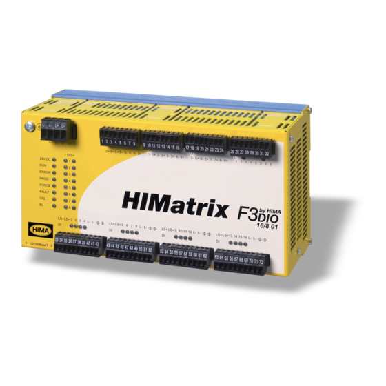
Structure
Describes the layout and function of remote I/Os and their communication via safeethernet, with front view and block diagram.
Product Data
Lists general product data, specifications for digital inputs, digital outputs, and pulsed outputs.
Certified HIMatrix F3 DIO 16/8 01
Lists certifications and standards (SIL, PL, ATEX) that the device complies with for safety applications.
Start-up
Installation and Mounting
Guides on mounting the remote I/O on a DIN rail and proper cable laying to avoid interference.
Digital Input and Output Terminals
Details terminal assignments for digital inputs and outputs, including sensor supply and ground connections.
Configuration Overview
Introduces I/O configuration using SILworX or ELOP II Factory based on firmware revision status.
SILworX Configuration Details
Guides on configuring I/O in SILworX via Hardware Editor, assigning variables to system parameters.
ELOP II Factory Configuration Details
Explains configuring I/O in ELOP II Factory by assigning signals from the Signal Editor.
Line Diagnosis Configuration
Guides on configuring line diagnosis for lamp/inductive and ohmic/capacitive loads in SILworX/ELOP II Factory.
Connection Variants
Describes proper device wiring for safety-related applications, covering different connection types.
Operation
Handling
States that no specific handling of the remote I/O is required during normal operation.
Diagnosis
Explains diagnosis via LED evaluation and diagnostic entries in the connected controller's memory.
Diagnostic Entries
Lists entries for error detection in line diagnosis, covering faulty parameter settings and channel faults.
Maintenance
Faults
Refers to previous chapters for fault reactions and describes the STOP_INVALID state upon critical faults.
Maintenance Measures
Outlines required measures: loading operating systems and executing proof tests.
Loading the Operating System
Guides on updating the device's operating system using the programming tool during system downtimes.
Proof Test
States that devices require proof tests every 10 years, referencing the Safety Manual.
Decommissioning
Transport
Disposal
Table of Contents
Print
Rename the bookmark
Delete bookmark?
Delete from my manuals?
Login
Sign In
OR
Sign in with Facebook
Sign in with Google
Upload manual
Upload from disk
Upload from URL
Need help?
Do you have a question about the F3 DIO 16/8 01 and is the answer not in the manual?
Questions and answers