
Subscribe to Our Youtube Channel
Related Manuals for HIMA HIMatrix F30 03


Summary of Contents for HIMA HIMatrix F30 03
- Page 1 HIMatrix Safety-Related Controller F30 03 Manual HIMA Paul Hildebrandt GmbH + Co KG Industrial Automation Rev. 1.00 HI 800 473 E...
- Page 2 HIMA directly. HIMA appreciates any suggestion on which information should be included in the manual. Equipment subject to change without notice. HIMA also reserves the right to modify the written material without prior notice. For further information, refer to the CD-ROM and our website http://www.hima.de and http://www.hima.com.
-
Page 3: Table Of Contents
F30 03 Table of Contents Table of Contents Introduction ............5 Structure and Use of this Manual................. 5 Target Audience..................... 5 Formatting Conventions ..................6 1.3.1 Safety Notes ......................6 1.3.2 Operating Tips ......................7 Safety ..............8 Intended Use ......................8 2.1.1 Environmental Requirements................... - Page 4 Table of Contents F30 03 Start-up ..............24 Installation and Mounting ..................24 4.1.1 Connecting the Digital Inputs ................. 24 4.1.1.1 Surges on Digital Inputs ..................25 4.1.2 Connecting the Digital Outputs................25 Sequence of Events Recording (SOE)..............26 Configuring the Controller with SILworX ............27 4.3.1 Processor Module ....................
-
Page 5: Introduction
HIMax system as an example Table 1: Additional Relevant Documents The latest manuals can be downloaded from the HIMA website at www.hima.com. The revision index on the footer can be used to compare the current version of existing manuals with the Internet edition. -
Page 6: Formatting Conventions
1 Introduction F30 03 Formatting Conventions To ensure improved readability and comprehensibility, the following fonts are used in this document: To highlight important parts Bold: Names of buttons, menu functions and tabs that can be clicked and used in the programming tool. For parameters and system variables Italics: Literal user inputs... -
Page 7: Operating Tips
F30 03 1 Introduction 1.3.2 Operating Tips Additional information is structured as presented in the following example: The text corresponding to the additional information is located here. Useful tips and tricks appear as follows: The tip text is located here. HI 800 473 E Rev. -
Page 8: Safety
2 Safety F30 03 Safety The following safety information, notes and instructions must be strictly observed. The product may only be used if all guidelines and safety instructions are adhered to. This product is operated with SELV or PELV. No imminent danger results from the product itself. -
Page 9: Residual Risk
F30 03 2 Safety Residual Risk No imminent danger results from a HIMatrix system itself. Residual risk may result from: Faults in the engineering Faults in the user program Faults in the wiring Safety Precautions Observe all local safety requirements and use the protective equipment required on site. Emergency Information A HIMatrix system is a part of the safety equipment of a site. -
Page 10: Product Description
(IEC 61508, IEC 61511 and IEC 62061) and PL e (EN ISO 13849-1). Further safety standards, application standards and test standards are specified in the certificate available on the HIMA website. Safety Function The controller is equipped with safety-related digital inputs and outputs. -
Page 11: Reaction In The Event Of A Fault
F30 03 3 Product Description 3.1.1.1 Reaction in the Event of a Fault If the device detects a fault on a digital input, the user program processes a low level in accordance with the de-energized to trip principle. The device activates the FAULT LED. In addition to the channel signal value, the user program must also consider the corresponding error code. -
Page 12: Safety-Related Digital Outputs
(two-pole connection) to ensure that the internal protective circuit can function. Inductive loads may be connected with no free-wheeling diode on the actuator. However, HIMA strongly recommends connecting a protective diode directly to the actuator. Page 12 of 46 HI 800 473 E Rev. 1.00... -
Page 13: Reaction In The Event Of A Fault
F30 03 3 Product Description 3.1.2.1 Reaction in the Event of a Fault If the device detects a faulty signal on a digital output, the affected module output is set to the safe (de-energized) state using the safety switches. If a fault in the device occurs, all digital outputs are switched off. In both cases, the devices activates the FAULT LED. -
Page 14: Equipment And Scope Of Delivery
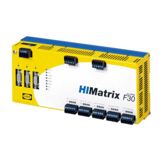
3 Product Description F30 03 Equipment and Scope of Delivery The available components and their part numbers are listed below: Designation Description Part no. F30 03 Compact controller with 20 digital inputs and 8 98 2200496 digital outputs. SILworX Operating temperature 0...+60 °C, for SILworX programming tool Table 3: Part Numbers... -
Page 15: Assembly
F30 03 3 Product Description Assembly This chapter describes the layout and function of the controller, and its connection for communication. Figure 5: Front View Digital Inputs Switch Safety-Related Processor System (CPU) Watchdog Communication System (COM) Digital Outputs Figure 6: Block Diagram HI 800 473 E Rev. -
Page 16: Led Indicators
3 Product Description F30 03 3.4.1 LED Indicators The light-emitting diodes (LEDs) indicate the operating state of the controller. The LEDs are classified as follows: Operating voltage LED System LEDs Communication LEDs I/O LEDs Fieldbus LEDs When the supply voltage is switched on, a LED test is performed and all LEDs are briefly lit simultaneously. -
Page 17: System Leds
F30 03 3 Product Description 3.4.1.2 System LEDs While the system is being booted, all LEDs are lit simultaneously. Color Status Description Device in RUN, normal operation Green A loaded user program is being executed. Device in STOP Blinking1 A new operating system is being loaded. The device is not in the RUN state or the STOP state. -
Page 18: Communication Leds
3 Product Description F30 03 3.4.1.3 Communication LEDs All RJ-45 connectors are provided with a small green and a yellow LEDs. The LEDs signal the following states: Status Description Green Full duplex operation Blinking1 IP address conflict, all communication LEDs are blinking Blinking-x Collision Half duplex operation, no collision... -
Page 19: Communication
F30 03 3 Product Description 3.4.2 Communication The controller communicates with remote I/Os via safeethernet. Up to 128 redundant safeethernet conections can be configured. 3.4.2.1 Connections for Ethernet Communication Property Description Port 4 x RJ-45 Transfer standard 10/100/Base-T, half and full duplex Auto negotiation Auto crossover IP address... -
Page 20: Network Ports Used For Ethernet Communication
3 Product Description F30 03 3.4.2.2 Network Ports Used for Ethernet Communication UDP ports SNTP (time synchronization between PES and remote I/O, PES and external devices) Modbus (can be modified by the user) 6010 safeethernet and OPC 6005/ 6012 If TCS_DIRECT was not selected in the HH network 8000 Programming and operation with SILworX 8004... -
Page 21: Reset Key
F30 03 3 Product Description 3.4.3 Reset Key The controller is equipped with a reset key. The key is only required if the user name or password for administrator access is not known. If only the IP address set for the controller does not match the PADT (PC), the connection can be established with a Route add entry on the PC. -
Page 22: Product Data
3 Product Description F30 03 Product Data General Total program and data memory 5 MB less 64 kBytes for CRCs for all application programs Response time ≥ 6 ms Ethernet interfaces 4 x RJ-45, 10/100BaseT (with 100 Mbit/s) with integrated switch Fieldbus interfaces 3 x 9-pole D-sub FB1 and FB2 with fieldbus submodule pluggable,... -
Page 23: Certified Himatrix F30
Version 3.0 November 2005 Table 15: Certificates Further safety standards and application standards are specified in the certificate. The certificate and the EC Type-Examination Certificate are available on the HIMA website at www.hima.com. HI 800 473 E Rev. 1.00 Page 23 of 46... -
Page 24: Start-Up
4 Start-up F30 03 Start-up To start up the controller, it must be mounted, connected and configured in SILworX. Installation and Mounting The controller is mounted on a 35 mm DIN rail such as described in the HIMatrix Manual for Compact Systems. -
Page 25: Surges On Digital Inputs
F30 03 4 Start-up 4.1.1.1 Surges on Digital Inputs Due to the short cycle time of the HIMatrix systems, a surge pulse as described in EN 61000-4-5 can be read in to the digital inputs as a short-term high level. The following measures ensure proper operation in environments where surges may occur: 1. -
Page 26: Sequence Of Events Recording (Soe)
4 Start-up F30 03 Sequence of Events Recording (SOE) Global variables of the controller can be monitored using the sequence of events recording. Global variables to be monitored are configured using the programming tool SILworX, see the online help and the SILworX Communication Manual (HI 801 101 E). Up to 4000 events can be configured. -
Page 27: Configuring The Controller With Silworx
F30 03 4 Start-up Configuring the Controller with SILworX In the Hardware Editor, the controller is represented like a base plate equipped with the following modules: Processor module (CPU) Communication module (COM) Input module (DI 20) Output module (DO 8) Double-click the module to open the detail view with the corresponding tabs. -
Page 28: Table 19: Configuration Parameters Of The Cpu And Com, Module Tab
4 Start-up F30 03 Parameter Description ARP Aging Time [s] A processor or COM module stores the MAC addresses of the communication partners in a MAC/IP address assignment table (ARP cache). If in a period of 1x...2x ARP Aging Time ... - ... -
Page 29: Tab: Routings
F30 03 4 Start-up 4.3.1.2 Tab: Routings The Routings tab contains the following parameters: Parameter Description Name Denomination of the routing settings IP Address Target IP address of the communication partner (with direct host routing) or network address (with subnet routing). Range of values: 0.0.0.0...255.255.255.255 Default value: 0.0.0.0 Subnet Mask... -
Page 30: Tab: Vlan (Port-Based Vlan)
4 Start-up F30 03 4.3.1.4 Tab: VLAN (Port-Based VLAN) For configuring the use of port-based VLAN. Should VLAN be supported, port-based VLAN should be off to enable each port to communicate with the other switch ports. For each port on one switch, the user can define which other ports of the switch received Ethernet frames may be sent to. -
Page 31: Tab: Mirroring
F30 03 4 Start-up 4.3.1.6 Tab: Mirroring Mirroring is used to configure whether the module should duplicate Ethernet packets on a given port such that they can be read from a device connected to that port, e.g., for test purposes. The following parameters define how a given port should work: This port does not participate to the mirroring process. -
Page 32: Digital Inputs For F30
4 Start-up F30 03 4.3.4 Digital Inputs for F30 The following tables present the statuses and parameters for the input module (DI 20) in the same order given in the SILworX Hardware Editor. 4.3.4.1 Tab: Module The Module tab contains the following system parameters: System parameter Description Data... -
Page 33: Tab: Do 20: Channels
F30 03 4 Start-up 4.3.4.2 Tab: DO 20: Channels The DI 20: Channels tab contains the following system parameters. System parameter Data Description Type Channel no. Channel number, defined by default -> Error Code BYTE Error codes for the digital input channels [BYTE] Coding Description... -
Page 34: Digital Outputs For F30
4 Start-up F30 03 4.3.5 Digital Outputs for F30 The following tables present the statuses and parameters for the output module (DO 8) in the same order given in the SILworX Hardware Editor. 4.3.5.1 Tab: Module The Module tab contains the following system parameters: System parameter Data Description... -
Page 35: Tab: Do 8: Channels
F30 03 4 Start-up 4.3.5.2 Tab: DO 8: Channels The DO 8: Channels tab contains the following system parameters. System parameter Data Description Type Channel no. Channel number, defined by default -> Error Code BYTE Error codes for the digital output channels [BYTE] Coding Description... -
Page 36: Operation
5 Operation F30 03 Operation The F30 controller is ready to operate. No specific monitoring is required for the controller. Handling Handling of the controller during operation is not required. Diagnosis A first diagnosis results from evaluating the LEDs, see Chapter 3.4.1. The device diagnostic history can also be read using the programming tool SILworX. -
Page 37: Maintenance
6.2.1 Loading the Operating System HIMA is continuously improving the operating system of the devices. HIMA recommends to use system downtimes to load a current version of the operating system into the devices. Refer to the release list to check the consequences of the new operation system version on the system! Load the operating system using the programming tool. -
Page 38: Decommissioning
7 Decommissioning F30 03 Decommissioning Remove the supply voltage to decommission the device. Afterwards pull out the pluggable screw terminal connector blocks for inputs and outputs and the Ethernet cables. Page 38 of 46 HI 800 473 E Rev. 1.00... -
Page 39: Transport
F30 03 8 Transport Transport To avoid mechanical damage, HIMatrix components must be transported in packaging. Always store HIMatrix components in their original product packaging. This packaging also provides protection against electrostatic discharge. Note that the product packaging alone is not suitable for transmission. HI 800 473 E Rev. -
Page 40: Disposal
F30 03 Disposal Industrial customers are responsible for correctly disposing of decommissioned HIMatrix hardware. Upon request, a disposal agreement can be arranged with HIMA. All materials must be disposed of in an ecologically sound manner. Page 40 of 46 HI 800 473 E Rev. 1.00... - Page 41 F30 03 9 Disposal HI 800 473 E Rev. 1.00 Page 41 of 46...
-
Page 42: Appendix
Appendix F30 03 Appendix Glossary Term Description Address Resolution Protocol: Network protocol for assigning the network addresses to hardware addresses Analog Input COMmunication module Cyclic Redundancy Check Digital Input Digital Output ElectroMagnetic Compatibility European Norm ElectroStatic Discharge FieldBus Function Block Diagrams Field Termination Assembly Fault Tolerance Time ICMP... -
Page 43: Index Of Figures
F30 03 Appendix Index of Figures Figure 1: Connections to Safety-Related Digital Inputs Figure 2: Line Control Figure 3: Connection of Actuators to Outputs Figure 4: Sample Type Label Figure 5: Front View Figure 6: Block Diagram Figure 7: Sample MAC Address Label Index of Tables Table 1: Additional Relevant Documents... -
Page 44: Index
Appendix F30 03 Index diagnosis..........36 part number ..........14 fault reaction safeethernet..........19 digital inputs .........11 specifications ........... 22 digital outputs ........13 SRS ............14 line control..........11, 13 surge............25 Page 44 of 46 HI 800 473 E Rev. 1.00... - Page 46 HIMA Paul Hildebrandt GmbH + Co KG P.O. Box 1261 68777 Brühl, Germany Phone: +49 6202 709-0 Fax: +49 6202 709-107 E-mail: info@hima.com Internet: www.hima.com (1124)
Need help?
Do you have a question about the HIMatrix F30 03 and is the answer not in the manual?
Questions and answers