
Subscribe to Our Youtube Channel
Related Manuals for HIMA DIO 24/16 01


Summary of Contents for HIMA DIO 24/16 01
- Page 1 HIMatrix Safety-Related Controller DIO 24/16 01 Manual HIMA Paul Hildebrandt GmbH + Co KG Industrial Automation Rev. 1.01 HI 800 205 E...
- Page 2 HIMA directly. HIMA appreciates any suggestion on which information should be included in the manual. Equipment subject to change without notice. HIMA also reserves the right to modify the written material without prior notice. For further information, refer to the CD-ROM and our website http://www.hima.de and http://www.hima.com.
-
Page 3: Table Of Contents
Connecting the Digital Inputs ................. 18 4.1.2.1 Surges on Digital Inputs..................19 4.1.3 Connecting the Digital Outputs ................19 4.1.4 Mounting the DIO 24/16 01 in Zone 2..............20 Configuration ....................... 21 4.2.1 Module Slots ......................21 Configuring the Module with SILworX ............... 21 4.3.1 Parameters and Error Codes for the Inputs and Outputs ........ - Page 4 Table of Contents DIO 24/16 01 4.3.2.2 DIO 24/16 01_1: DO Channels Tab ..............24 4.3.2.3 DIO 24/16 01_1: DI Channels Tab ................ 24 Configuring a Module Using ELOP II Factory............ 25 4.4.1 Configuring the Inputs and Outputs................ 25 4.4.2 Signals and Error Codes for the Inputs and Outputs..........
-
Page 5: Introduction
DIO 24/16 01 1 Introduction Introduction This manual describes the technical characteristics of the module and its use. It also includes instructions on how to install, start up and replace it. Structure and Use of this Manual The content of this manual is part of the hardware description of the HIMatrix programmable electronic system. -
Page 6: Target Audience
ELOP II Factory Table 2: Additional Relevant Documents The latest manuals can be downloaded from the HIMA website www.hima.com. The revision index on the footer can be used to compare the current version of existing manuals with the Internet edition. -
Page 7: Operating Tips
DIO 24/16 01 1 Introduction Consequences arising from the danger Danger prevention SIGNAL WORD Type and source of danger! Consequences arising from the danger Danger prevention The signal words have the following meanings: Danger indicates hazardous situation which, if not avoided, will result in death or serious injury. -
Page 8: Safety
2 Safety DIO 24/16 01 Safety The following safety information, notes and instructions must be strictly observed. The product may only be used if all guidelines and safety instructions are adhered to. This product is operated with SELV or PELV. No imminent danger results from the product itself. -
Page 9: Residual Risk
DIO 24/16 01 2 Safety Residual Risk No imminent danger results from a HIMatrix system itself. Residual risk may result from: Faults in the engineering Faults in the user program Faults in the wiring Safety Precautions Observe all local safety requirements and use the protective equipment required on site. -
Page 10: Product Description
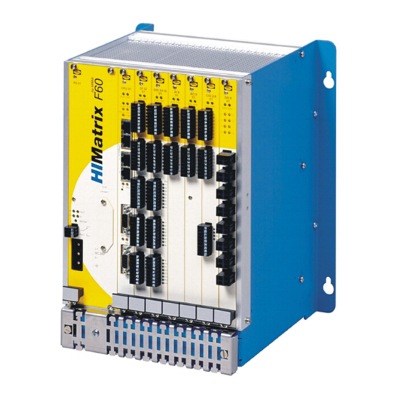
DIO 24/16 01 is a plug-in module for the modular F60 HIMatrix system. The DIO 24/16 01 module has 24 digital input channels and 16 digital output channels that are galvanically isolated from the I/O bus. The status of the input and output signals is displayed by LEDs located on the front plate next to the terminal plugs. -
Page 11: Safety-Related Outputs
3.1.3 Line Control The digital outputs DO 1 through DO 8 of the DIO 24/16 01 module can be used to monitor the own digital inputs or the digital inputs of other modules (e.g., DI 32 01) for short-circuits and open-circuits, e.g., for an EMERGENCY STOP button complying with Cat. 4 in accordance with EN 954-1. - Page 12 3 Product Description DIO 24/16 01 Figure 1: Sample Type Label Page 12 of 40 HI 800 205 E Rev. 1.01...
-
Page 13: Assembly
DIO 24/16 01 3 Product Description Assembly This chapter describes the layout and function of the plug-in module. 3.4.1 Block Diagram 24 Digital Inputs 16 Digital Outputs Module Indicators I/O Bus Figure 2: Block Diagram HI 800 205 E Rev. 1.01... -
Page 14: Front View
3 Product Description DIO 24/16 01 3.4.2 Front View DIO 24/16 RUN ERR Figure 3: Front View Page 14 of 40 HI 800 205 E Rev. 1.01... -
Page 15: Module Indicators
DIO 24/16 01 3 Product Description 3.4.3 Module Indicators Color Status Description Green Operating voltage present No operating voltage Module faulty or external faults Reaction as dictated by the diagnosis No module faults and / or no channel faults Table 5: Module Indicators 3.4.4... -
Page 16: Table 9: Specifications For The Digital Outputs
3 Product Description DIO 24/16 01 Digital outputs Number of outputs 16 (galvanically isolated) Output voltage 18.4...26.8 VDC Internal voltage drop max. 2 W at 2 A Output current 2 A each channel, max. 8 A each module, (at 30 °C) -
Page 17: Start-Up
DIO 24/16 01 4 Start-Up Start-Up To start up the controller, it must be mounted, connected and configured in the programming tool. Installation and Mounting The module is mounted in the subrack of the modular HIMatrix F60 system. 4.1.1 Mounting and Removing the Modules To mount and remove the modules, the connection cable clamp terminals must be unplugged. -
Page 18: Connecting The Digital Inputs
4 Start-Up DIO 24/16 01 4.1.2 Connecting the Digital Inputs Use the following terminals to connect the digital inputs: Terminal Designation Function Supply of inputs 1...8 Digital input 1 Digital input 2 Digital input 3 Digital input 4 Digital input 5... -
Page 19: Surges On Digital Inputs
DIO 24/16 01 4 Start-Up 4.1.2.1 Surges on Digital Inputs Due to the short cycle time of the HIMatrix systems, a surge pulse as described in EN 61000-4-5 can be read in to the digital inputs as a short-term high level. -
Page 20: Mounting The Dio 24/16 01 In Zone 2
(PV) of each HIMatrix F60 DIO 24/16 01 module is 25 W at maximum output load. 3. The HIMatrix F60 DIO 24/16 01 module must be supplied with 24 VDC from a power supply unit with safe isolation. Only power supply units of type PELV or SELV may be used. -
Page 21: Configuration
DIO 24/16 01 4 Start-Up Configuration The DIO 24/16 01 can be configured using a programming tool, SILworX or ELOP II Factory. Which programming tool should be used depends on the revision status of the operating system (firmware): ELOP II Factory is required for operating system versions prior to 7. -
Page 22: Parameters And Error Codes For The Inputs And Outputs
4 Start-Up DIO 24/16 01 4.3.1 Parameters and Error Codes for the Inputs and Outputs The following tables specify the system parameters that can be read and set for the inputs and outputs, including the corresponding error codes. In the user program, the error codes can be read using the variables assigned within the logic. -
Page 23: Table 13: Silworx - System Parameters For Digital Outputs And Inputs, Module Tab
DIO 24/16 01 4 Start-Up System parameter Data type Description DO.Error Code WORD Error codes for all digital outputs Coding Description 0x0001 Module fault 0x0002 MOT test safety switch 1 faulty 0x0004 MOT test safety switch 2 faulty 0x0008 FTT test of test pattern faulty... -
Page 24: Dio 24/16 01_1: Do Channels Tab
4 Start-Up DIO 24/16 01 4.3.2.2 DIO 24/16 01_1: DO Channels Tab The DIO 24/16 01_1: DO Channels tab contains the following system variables: System Data Description parameter type BYTE Input values for the digital input channels -> Error Code... -
Page 25: Configuring A Module Using Elop Ii Factory
DIO 24/16 01 4 Start-Up Configuring a Module Using ELOP II Factory 4.4.1 Configuring the Inputs and Outputs The signals previously defined in the Signal Editor (Hardware Management) are assigned to the individual channels (inputs and outputs) using ELOP II Factory. Refer to the System... -
Page 26: Table 16: Elop Ii Factory - Digital Input System Signals
4 Start-Up DIO 24/16 01 System Signal Description DI[xx].Value [BOOL] Input values for the digital input channels 0 = input de-energized 1 = input energized DI Number of Number of pulsed outputs (supply outputs) Pulsed Channels Coding Description [USINT] No output planned for LS/LB... -
Page 27: Digital Outputs
DIO 24/16 01 4 Start-Up 4.4.4 Digital outputs System Signal Description Mod.SRS [UDINT] Slot number (System Rack Slot) Mod. Type [UINT] Type of module, target value: 0xFE01 [65025 Mod. Error Code Error codes for the module [WORD] Coding Description 0x0000... -
Page 28: Operation
5 Operation DIO 24/16 01 Operation The module runs within a HIMatrix base plate and does not require any specific monitoring. Handling Handling of the controller during operation is not required. Diagnosis A first diagnosis results from evaluating the LEDs, see Chapter 3.4.3. -
Page 29: Maintenance
DIO 24/16 01 6 Maintenance Maintenance No maintenance measures are required during normal operation. If a device or module fails, it must be replaced with a faultless device or module of the same type or with an approved replacement model. -
Page 30: Maintenance Measures
Executing the proof test 6.2.1 Loading the Operating System HIMA is continuously improving the operating system of the controller. HIMA recommends to use system downtimes to load a current version of the operating system into the controller. Refer to the release list to check the consequences of the new operation system version on the system! Load the operating system using the programming tool. -
Page 31: Decommissioning
DIO 24/16 01 7 Decommissioning Decommissioning Remove the supply voltage to decommission the module. Afterwards pull out the pluggable screw terminal connector blocks for inputs and outputs and the Ethernet cables. HI 800 205 E Rev. 1.01 Page 31 of 40... -
Page 32: Transport
8 Transport DIO 24/16 01 Transport To avoid mechanical damage, HIMatrix components must be transported in packaging. Always store HIMatrix components in their original product packaging. This packaging also provides protection against electrostatic discharge. Note that the product packaging alone is not suitable for transmission. -
Page 33: Disposal
9 Disposal Disposal Industrial customers are responsible for correctly disposing of decommissioned HIMatrix hardware. Upon request, a disposal agreement can be arranged with HIMA. All materials must be disposed of in an ecologically sound manner. HI 800 205 E Rev. 1.01... - Page 34 9 Disposal DIO 24/16 01 Page 34 of 40 HI 800 205 E Rev. 1.01...
-
Page 35: Appendix
DIO 24/16 01 Appendix Appendix Glossary Term Description Address Resolution Protocol: Network protocol for assigning the network addresses to hardware addresses Analog Input COMmunication module Cyclic Redundancy Check Digital Input Digital Output ELOP II Factory Programming tool for HIMatrix systems... -
Page 36: Index Of Figures
Appendix DIO 24/16 01 Index of Figures Figure 1: Sample Type Label Figure 2: Block Diagram Figure 3: Front View Figure 4: Label for Ex Conditions Page 36 of 40 HI 800 205 E Rev. 1.01... -
Page 37: Index Of Tables
DIO 24/16 01 Appendix Index of Tables Table 1: HIMatrix System Variants Table 2: Additional Relevant Documents Table 3: Environmental Requirements Table 4: Part Numbers Table 5: Module Indicators Table 6: I/O LEDs Table 7: Product Data Table 8: Specifications for Digital Inputs... -
Page 38: Index
Appendix DIO 24/16 01 Index diagnosis..........28 line control ..........11 fault reaction part number ..........11 digital inputs .........10 specifications ........... 15 digital outputs ........11 surge............19 Page 38 of 40 HI 800 205 E Rev. 1.01... - Page 40 HIMA Paul Hildebrandt GmbH + Co KG P.O. Box 1261 68777 Brühl, Germany Tel: +49 6202 709-0 Fax: +49 6202 709-107 E-mail: info@hima.com Internet: www.hima.com (1022)
Need help?
Do you have a question about the DIO 24/16 01 and is the answer not in the manual?
Questions and answers