HIMA HIMatrix F60 Manual
Safety-related controller
Hide thumbs
Also See for HIMatrix F60:
- Engineering manual (64 pages) ,
- Manual (38 pages) ,
- System manual (110 pages)

Related Manuals for HIMA HIMatrix F60


Summary of Contents for HIMA HIMatrix F60
- Page 1 HIMatrix Safety-Related Controller System Manual Modular Systems HIMA Paul Hildebrandt GmbH + Co KG Industrial Automation Rev. 2.02 HI 800 191 E...
- Page 2 All HIMA products mentioned in this manual are protected by the HIMA trade-mark. Unless noted otherwise, this also applies to other manufacturers and their respective products referred to herein. All of the instructions and technical specifications in this manual have been written with great care and effective quality assurance measures have been implemented to ensure their validity.
-
Page 3: Table Of Contents
System Manual Modular Systems Table of Contents Table of Contents Introduction Structure and Use of the Document Target Audience Formatting Conventions 1.3.1 Safety Notes 1.3.2 Operating Tips Service and Training Safety Intended Use 2.1.1 Scope 2.1.1.1 Application in Accordance with the De-Energize to Trip Principle 2.1.1.2 Application in Accordance with the Energize to Trip Principle 2.1.1.3... - Page 4 Table of Contents System Manual Modular Systems Licensing with CPU 03 Communication HIMatrix Communication Protocols Ethernet Communication 4.2.1 safeethernet 4.2.2 Maximum Communication Time Slice 4.2.3 Connectors for safeethernet/Ethernet 4.2.4 Communication with the PADT 4.2.5 Ethernet Communication Protocols 4.2.5.1 SNTP 4.2.5.2 Modbus TCP 4.2.5.3 Send &...
- Page 5 System Manual Modular Systems Table of Contents 7.1.1 Heat Dissipation 7.1.1.1 Definitions 7.1.1.2 Installation Type 7.1.1.3 Natural Convection Installation and Mounting 7.2.1 Mounting 7.2.2 Construction Depth 7.2.3 Mounting on a Flat Base 7.2.4 Mounting and Removing the Modules 7.2.5 Connecting the Input and Output Circuits 7.2.6 Earthing and Shielding 7.2.6.1...
- Page 6 Table of Contents System Manual Modular Systems 7.7.4 Configure Line Control 7.7.4.1 Required Signals 7.7.4.2 Configuring Pulsed Outputs 7.7.4.3 Configuration Example with ELOP II Factory 7.7.5 Generating the Code for the Resource Configuration 7.7.6 Configuring the System ID and the Connection Parameters 7.7.7 Loading a Resource Configuration after a Reset 7.7.8...
- Page 7 System Manual Modular Systems Table of Contents Index of Figures Index of Tables Declaration of Conformity Index HI 800 191 E Rev. 2.02 Page 7 of 114...
- Page 8 Table of Contents System Manual Modular Systems Page 8 of 114 HI 800 191 E Rev. 2.02...
-
Page 9: Introduction
1 Introduction Introduction The modular HIMatrix F60 system described in this manual is safety-related and can be used for various purposes. The following conditions must be met to safely install and start up the HIMatrix automation devices, and to ensure safety during their operation and maintenance: ... -
Page 10: Table 2: Additional Relevant Documents
HI 800 006 E Table 2: Additional Relevant Documents The latest manuals can be downloaded from the HIMA website at www.hima.com. The revision index on the footer can be used to compare the current version of existing manuals with the Internet edition. -
Page 11: Target Audience
System Manual Modular Systems 1 Introduction In addition to the Table 2 documents, the manuals specific to the F60 modules in use must be taken into account. Target Audience This document addresses system planners, configuration engineers, programmers of automation devices and personnel authorized to implement, operate and maintain the modules and systems. -
Page 12: Operating Tips
HIMA holds training, usually in-house, for software programs and the hardware of the controllers. Additionally, customer training can be offered on-site. Refer to the HIMA website at www.hima.com for the current training program and dates. Offers for specialized, on-site training can also be provided upon request. -
Page 13: Safety
System Manual Modular Systems 2 Safety Safety All safety information, notes and instructions specified in this document must be strictly observed. The product may only be used if all guidelines and safety instructions are adhered to. The product is operated with SELV or PELV. No imminent risk results from the product itself. The use in Ex-Zone is permitted if additional measures are taken. -
Page 14: Environmental Requirements
2 Safety System Manual Modular Systems Environmental Requirements Requirement type Range of values Protection class Protection class III in accordance with IEC/EN 61131-2 Ambient temperature 0...+60 °C Storage temperature -40...+85 °C Pollution Pollution degree II in accordance with IEC/EN 61131-2 Altitude <... -
Page 15: Climatic Requirements
System Manual Modular Systems 2 Safety 2.2.1.1 Climatic Requirements The following table lists the most important tests and limits for climatic requirements: IEC/EN 61131-2 Climatic tests Operating temperature: 0...+60 °C (test limits: -10...+70 °C) Storage temperature: -40...+85 °C Dry heat and cold resistance tests: +70 °C / -25 °C, 96 h, power supply not connected Temperature change, resistance and immunity test:... -
Page 16: Power Supply
2 Safety System Manual Modular Systems IEC/EN 61000-6-4 Noise emission tests EN 55011 Emission test: Class A radiated, conducted Table 9: Noise Emission Tests 2.2.1.4 Power Supply The following table lists the most important tests and limits for the HIMatrix systems' power supply: IEC/EN 61131-2 Verification of the DC supply characteristics... -
Page 17: Esd Protective Measures
If not used, ensure that the modules are protected from electrostatic discharge, e.g., by storing them in their packaging. Residual Risk No imminent risk results from a modular HIMatrix F60 system itself. Residual risk may result from: Faults related to engineering ... -
Page 18: Product Description
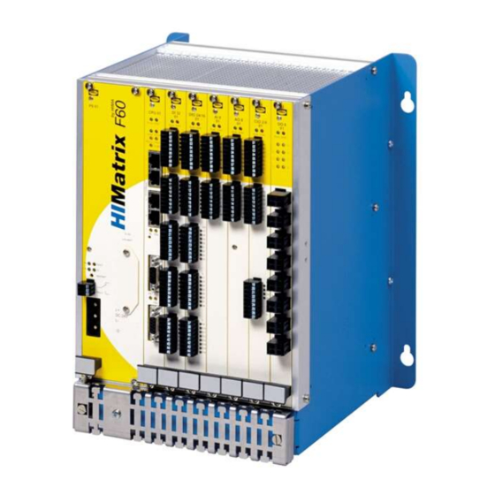
The modular system F60 can also be connected to HIMatrix compact systems via safeethernet. Modules All modules of the HIMatrix F60 system are 6 rack units (RU) high, which correspond to 262 mm. Specific slots are only reserved for the power supply module and the CPU module, see above. -
Page 19: Outputs
Do not plug the terminals for output circuits if a load is connected. If short-circuits are present, the resulting high current may damage the terminals. Inductive loads may be connected with no free-wheeling diode on the actuator. However, HIMA recommends connecting a protective diode directly to the actuator. -
Page 20: Supply Voltage Monitoring
3 Product Description System Manual Modular Systems Configurable 5...2000 µs Figure 2: Pulsed Signals T1 and T2 The digital outputs DO are pulsed (briefly set to low level), to monitor the wires connected to the digital inputs. The time base of the test pulse can be configured within 5...2000 μs (default value 400 μs). -
Page 21: Monitoring The Temperature State
The Temperature State system variable allows the user to read the temperature. If the state Very high temperature often occurs, HIMA recommends improving the system heat dissipation, e.g., by taking additional ventilation or cooling measures, such that the long life time of the HIMatrix systems can be maintained. -
Page 22: Short-Circuit Reaction Of Output Channels
3 Product Description System Manual Modular Systems Short-Circuit Reaction of Output Channels If a short-circuit occurs in an output channel, the HIMatrix automation systems switch off the affected channel. If multiple short-circuits occur, the channels are switched off individually in accordance with their current input. -
Page 23: Recording Events
Reload Sequence of events recording The software activation code can be generated on the HIMA website using the system ID of the controller (value 1...65 535). To this end, the SMR license must be activated. HI 800 191 E Rev. 2.02... - Page 24 3 Product Description System Manual Modular Systems The software activation code is intrinsically tied to this system ID. One license can only be used one time for a specific system ID. For this reason, only activate the code when the system ID has been uniquely defined.
-
Page 25: Communication
(invalid configuration). Order the software activation code on time! The software activation code can be generated on the HIMA website using the system ID of the controller (value 1...65 535). The software activation code is intrinsically tied to this system ID. One license can only be used one time for a specific system ID. - Page 26 4 Communication System Manual Modular Systems Example of other F60 Superior safeethernet PADT PADT Figure 3: safeethernet/Ethernet Networking Example The different systems can be connected to one another via Ethernet in any configuration (e.g., star or linear network); a PADT may also be connected to any device. Page 26 of 114 HI 800 191 E Rev.
-
Page 27: Maximum Communication Time Slice
System Manual Modular Systems 4 Communication NOTE Ethernet operation may be disturbed! Ensure that no network rings result from interconnecting the controllers. Data packets may only travel to a system over a single path. If controllers and remote I/Os with different versions of operating systems are connected via safeethernet, the following cases must be observed: Operating system of Operating system of... -
Page 28: Ethernet Communication Protocols
4.2.5.1 SNTP The SNTP protocol (simple network time protocol) is used to synchronize the time of the HIMA resources via Ethernet. The current time can be retrieved via Ethernet in predefined time intervals from a PC, or a HIMA resource configured as SNTP server. -
Page 29: Fieldbus Communication
The two fieldbus interfaces FB1 and FB2 of the processor module can be freely equipped with fieldbus submodules. Only HIMA is authorized to mount the fieldbus submodules; failing which the warranty will be void. Some fieldbus submodules are shown in Table 16. All available fieldbus submodules are listed in the SILworX communication manual (HI 801 101 E). - Page 30 4 Communication System Manual Modular Systems No safety-related communication can be ensured with the available fieldbus protocols. The communication system with fieldbus interfaces is connected to the safety-related processor system. Only devices with safe electrical separation may be connected to the interfaces. The fieldbus submodules PROFIBUS master can be used on controllers F20, F30, F35 or F60 with hardware revision 02.
-
Page 31: Operating System
The valid versions of the operating system and corresponding signatures (CRCs) are documented in a list maintained by HIMA in co-operation with the TÜV. Additional features of one operating system version can only be used if a corresponding version of the programming tool is used. -
Page 32: Permanent Faults On Inputs Or Outputs
5 Operating System System Manual Modular Systems Permanent faults on inputs or outputs Temporary faults on inputs or outputs Internal Faults 5.3.1 Permanent Faults on Inputs or Outputs A fault on an input or output channel has not effect on the controller. The operating system only considers the defective channel as faulty, and not the entire controller. -
Page 33: Modes Of Operation For The Processor System
System Manual Modular Systems 5 Operating System 5.4.1 Modes of Operation for the Processor System LEDs located on the front plate of the controller indicate the operating state of the processor system. The latter can also be reported by the PADT, together with other parameters specific to processor module and user program. -
Page 34: User Program
6 User Program System Manual Modular Systems User Program In accordance with the IEC 61131-3 requirements, a PADT with installed programming tool, i.e., ELOP II Factory or SILworX, must be used to create and load the user program for the PES. First, use the PADT to create and configure the user program for the controller's safety-related operation. -
Page 35: Multitasking
System Manual Modular Systems 6 User Program determine the cycle time in the user program may result in inaccurate cycle times, potentially exceeding the watchdog time. In the third phase, the user program results are forwarded for being processed in the following cycles and supplied to the output channels. -
Page 36: Table 20: Parameters Configurable For Multitasking
6 User Program System Manual Modular Systems reason, the reaction to this input change is only available at the end of CPU cycle The reaction time of Prg 2 is two times longer than that of Prg 1. Upon completion of the first part of the Prg 2 cycle under consideration, Prg 2 processing is completely aborted and only resumed when starts. -
Page 37: Multitasking Mode
HIMA recommends to set the Max. Duration for each Cycle [µs] parameter to an appropriate value ≠ 0. This ensures that a user program with an excessively long runtime is stopped during the current CPU cycle and resumed in the next CPU cycle without affecting the other user programs. - Page 38 6 User Program System Manual Modular Systems 1. Multitasking Mode 1 uses the unneeded time to reduce the CPU cycle. If the user program is completely processed, processing of the next user program begins immediately. In total, this results in a shorter cycle. Example: 3 user programs (Prg 1, Prg 2 and Prg 3) that allow a user program cycle to take up to 3 CPU cycles.
- Page 39 System Manual Modular Systems 6 User Program 2. In Multitasking Mode 2, the unneeded duration of lower-priority user programs is distributed among higher-priority user programs. In addition to the specified Max. Duration for Each Cycle [µs], these user programs can use the portions of unneeded duration. This procedure ensures high availability.
- Page 40 6 User Program System Manual Modular Systems The unused execution time of user programs that were not run cannot be exploited as residual time by other user programs. User programs are not run if they are in one of the following states: ...
-
Page 41: Reload - With Cpu 03
System Manual Modular Systems 6 User Program In the examples illustrating the multitasking modes, input and output processing are represented as empty spaces at the beginning and the end of each CPU cycle. Reload - with CPU 03 If user programs were modified, the changes can be transferred to the PES during operation. The operating system checks and activates the modified user program which then assumes the control task. -
Page 42: Table 21: Reloading After Changes
6 User Program System Manual Modular Systems The user is responsible for ensuring that the watchdog time includes a sufficient reserve time. This should allow the user to manage the following situations: Variations in the user program's cycle time ... -
Page 43: General Information
Only remove existing forcing restrictions with the consent of the test authority. When forcing values, the person in charge must take further technical and organizational measures to ensure that the process is sufficiently monitored in terms of safety. HIMA recommends to setting a time limit for the forcing procedure, see below. -
Page 44: Forcing In Connection With F*03
6 User Program System Manual Modular Systems 6.5.1 Forcing in Connection with F*03 To force a global or local variable, the following conditions must be met: The corresponding force switch is set. Forcing was started. If forcing was started, a change to the force switch has an immediate effect. If forcing was started and the force switch is set, a change to the force value has an immediate effect. - Page 45 System Manual Modular Systems 6 User Program Absolutely take the following restrictions into account when forcing or evaluating online tests performed with forced global variables: Global Variables To force a global variable, the following conditions must be met: The corresponding force switch is set. ...
-
Page 46: Restriction To The Use Of Forcing
6 User Program System Manual Modular Systems 6.5.3 Restriction to the Use of Forcing The following measures can be configured to limit the use of forcing and thus avoid potential faults in the safety functionality due to improper use of forcing: ... -
Page 47: Configuration Parameters For Forcing
System Manual Modular Systems 6 User Program To manually stop forcing, click the Stop button in the Force Editor. By doing so, the controller maintains the RUN state since the timeout has not been attained and the Stop at Force Timeout reaction was not defined. -
Page 48: Start-Up
7 Start-Up System Manual Modular Systems Start-Up Commissioning of modular HIMatrix system comprises the following phases: Mounting the subrack in a suitable location and its assembly with modules. Take the dissipation of the generated heat into account. Electrical connection of power supply, earthing, sensors, and actuators ... -
Page 49: Natural Convection
7.2.1 Mounting The location for installing a HIMatrix F60 subrack must be chosen observing the operating requirements (see Chapter 2.2) to ensure a smooth operation. HI 800 191 E Rev. 2.02 Page 49 of 114... -
Page 50: Construction Depth
7.2.2 Construction Depth Due to the connections for communication and I/O level, the HIMatrix F60 system has a construction depth of 270 mm. The construction depth is measured from the mounting rail. Page 50 of 114... -
Page 51: Mounting On A Flat Base
System Manual Modular Systems 7 Start-Up 7.2.3 Mounting on a Flat Base The F60 subrack is equipped with two perpendicular joint bars each of which has two oblong holes for fastening. These joint bars must be secured on a flat base. The mounting bolts must not exceed 6 mm in diameter and 13 mm head diameter. -
Page 52: Earthing And Shielding
7 Start-Up System Manual Modular Systems 2. Use a clamp to connect the shielding of a cable (if present) to the earth grid. To this end, place the clamp over the surface of the stripped cable shielding and press it from both sides into the oblong holes of the earth grid until it snaps into position. -
Page 53: Earthing Connections
System Manual Modular Systems 7 Start-Up 7.2.6.2 Earthing Connections All HIMatrix devices have labeled screws for earthing. The wire cross-section for the connection to the screw is 2.5 mm . The earth wires must be as short as possible. The earthing screw is located on the front, left side of the earth grid and is labeled with the earthing symbol. -
Page 54: Using The Reset Key With The Cpu 01 And Cpu 03 Modules
7 Start-Up System Manual Modular Systems NOTE Damage of the device possible! Do not exchange the terminals L+ and L-, or connect them to other terminals of the device! In case of a false connection, a pre-fuse blows to prevent the device from being damaged. -
Page 55: Resource Properties
System Manual Modular Systems 7 Start-Up 7.3.1.1 Resource Properties The system parameters of the resource determine the controller behavior during operation and can be set in SILworX, in the Properties dialog box of the resource. Parameter Description Default Setting for safe value operation Name... - Page 56 7 Start-Up System Manual Modular Systems Parameter Description Default Setting for safe value operation Allow Online All the switches/parameters listed below OFF OFF is Settings can be changed online using the PADT. recommended OFF: These parameters may These parameters may not be changed online be changed online if ...
-
Page 57: Table 26: System Parameters Of The Resource - Cpu Os V7 And Higher
System Manual Modular Systems 7 Start-Up safeethernet CRC SILworX The CRC for safeethernet is created as in Current Application- V2.36.0 SILworX V2.36.0. This setting is required for Version specific exchanging data with resources planned with SILworX V2.36 or previous versions. Current The CRC for safeethernet is created with the Version... -
Page 58: Parameters For The Remote I/Os
Alive Interval. 250…29 950 ms Alive Interval [ms] <= Resend Time [ms] - 50 ms. HIMA recommends using values equal to or greater than the default value to ensure that the network is only loaded if required. -
Page 59: Hardware System Variables For Reading The Parameters
System Manual Modular Systems 7 Start-Up Read-only in RUN After starting the controller, no operating action Application- such as stop, start or download is permitted in FALSE specific SILworX , except for forcing and reload. Relay Contact 1 Only applicable with F60! Application- ...Relay Contact 4 FALSE... - Page 60 7 Start-Up System Manual Modular Systems Variable Description Data Type Force Deactivation Forcing is deactivated. BOOL OFF: Forcing is possible. Forcing Active Global or local forcing is active. BOOL OFF: Global and local forcing are not active. Force Switch State State of the force switch UDINT 0xFFFFFFFE No force switch set...
-
Page 61: Table 30: Hardware System Variables For Reading The Parameters
System Manual Modular Systems 7 Start-Up Variable Description Data Type OFF: Loading by performing a reload is possible Reload Cycle With F*03 devices only! BOOL TRUE during the first cycle after a reload, otherwise FALSE CPU Safety Time [ms] Safety time set for the controller in ms UDINT Start Allowed Start of processor system using PADT is allowed... -
Page 62: Rack System Parameter Settings
7 Start-Up System Manual Modular Systems 7.3.1.5 Rack System Parameter Settings The rack system parameters can be set in the Rack's online view. Parameter Description Default value Type Spare, not changeable Name Rack name for the controller, text HIMatrix F...Rack Rack ID Not changeable Temperature Monitoring... -
Page 63: Configuring The Inputs And Outputs
System Manual Modular Systems 7 Start-Up Switch / Function Default Setting for value Parameter safe operation Classification Classification of the user program: Safety-related or Safety- Application- Standard (for documentation only). related specific Allow Online It enables changes of other user program switches during Settings operation. - Page 64 7 Start-Up System Manual Modular Systems 3. In the Detail View, open the tab with the required channels. The system variables for the channels appear. Use of Digital Input To use the value of a digital input in the user program 1.
-
Page 65: Configure Line Control
System Manual Modular Systems 7 Start-Up The global variable provides values to the user program. To get additional options for programming fault reactions in the user program, assign global variable to Counter.Error Code and Module Error Code. Refer to the manual of the compact system or module for more details on how to use the error codes and other parameters of the counter input. -
Page 66: Configuring Pulsed Outputs
7 Start-Up System Manual Modular Systems Name Type Description Initial Remark Value Sum_Pulse USINT Number of pulsed 1...8, as required outputs Board_POS_P UDINT Module slot with pulsed With compact devices, the ulse outputs DOs are used in slot 1, 2 or 3, see Table 35. -
Page 67: Configuration Example With Silworx
System Manual Modular Systems 7 Start-Up SILworX Examples of permitted configurations ..of not permitted Value [BOOL] -> Channel no. 1 Pulse_ON Pulse_ON Pulse_ON Pulse_ON Channel no. 2 Pulse_ON Pulse_ON Pulse_ON Pulse_ON Pulse_ON Channel no. 3 Pulse_ON Pulse_ON Pulse_ON Pulse_ON Channel no. -
Page 68: Generating The Resource Configuration
7 Start-Up System Manual Modular Systems The following table shows the connection of the system variables in the input module's Detail View to global variables: System variable Global Variable S1_1_Pulsed…S2_2_Pulsed (one variable for each -> Value [BOOL] of the corresponding channel channel) FC_S1_1_Pulsed…FC_S2_2_Pulsed (one variable... -
Page 69: Loading A Resource Configuration After A Reset
System Manual Modular Systems 7 Start-Up The Write via MAC dialog box appears. 6. Type correct values for the connection parameters and the SRS, and enter the access data for a user account with administrator rights valid on the controller. Click Write. Connection data and S.R.S are configured and it is now possible to log in. -
Page 70: Loading A Resource Configuration From The Flash Memory Of The Communication System
7 Start-Up System Manual Modular Systems 7.3.10 Loading a Resource Configuration from the Flash Memory of the Communication System If data errors were detected in the NVRAM thus causing the watchdog time to be exceeded, it can be useful to load the resource configuration from the flash memory for the communication system instead of from the PADT: If the Control Panel (CP) is no longer accessible, the connection parameters for the project must be reset in the controller, see Chapter 7.3.7. -
Page 71: User Management In Silworx - Cpu Os V7 And Higher
System Manual Modular Systems 7 Start-Up - Use the PADT date and time - to transfer the time and date displayed for the PADT into the controller. - User-defined - to transfer the date and time from the two input boxes into the controller. Make sure that the format used for date and time is correct! 6. - Page 72 7 Start-Up System Manual Modular Systems Each user account is composed of name, password and access right. The user data can be used to log in once a download has been performed to load the project into the controller. The user accounts of a controller can also be used for the corresponding remote I/Os.
-
Page 73: Setting Up User Accounts
System Manual Modular Systems 7 Start-Up Parameters for User Accounts To set up new user accounts, the following parameters must be set: Parameter Description User Name User name or ID to log in to a controller. The user name must not contain more than 32 characters (recommended: a maximum of 16 characters) and may only be composed of letters (A ... -
Page 74: Configuration With Silworx - Cpu Os V7 And Higher
7 Start-Up System Manual Modular Systems Configuration with SILworX - CPU OS V7 and Higher This chapter describes how to configure communication using SILworX for processor operating systems V7 and higher. Depending on the application, the following elements must be configured: ... -
Page 75: Configuring Alarms And Events - With Cpu
System Manual Modular Systems 7 Start-Up Name Explanation Port Port number as printed on the housing; per port, only one configuration may exist. Range of values: 1...n, depending on the resource Speed [Mbit/s] 10 Mbit/s: Data rate 10 Mbit/s 100 Mbit/s: Data rate 100 Mbit/s Autoneg (10/100): Automatic baud rate setting Standard: Autoneg Flow Control... -
Page 76: Table 42: Parameters For Boolean Events
7 Start-Up System Manual Modular Systems The parameters of the Boolean events must be entered in a table with the following columns: Column Description Range of values Name Name for the event definition; it must be unique within the Text, max. 32 resource. - Page 77 System Manual Modular Systems 7 Start-Up The parameters of the scalar events must be entered in a table with the following columns: Column Description Range of values Name Name for the event definition; it must be unique within the Text, max. 32 resource.
-
Page 78: Configuring A Resource Using Elop Ii Factory - Cpu Os Up To V7
7 Start-Up System Manual Modular Systems Column Description Range of values LL Alarm Activated The user must confirm that the lowest limit (LL) has Checkbox activated, Acknowledgment been exceeded (acknowledgment). deactivated Required Deactivated The user may not confirm that the lowest limit (LL) has been exceeded. -
Page 79: Configuring The User Program
System Manual Modular Systems 7 Start-Up Parameter Range Description Default value Off: Load not allowed Test Mode On/Off Test Mode Allowed Test Mode Allowed Off: Test mode not allowed Changing the On/Off Changing variables in the online test variables in the Allowed OLT allowed Off:... -
Page 80: Table 45: General System Signals And Parameters - Cpu Os Up To V7
7 Start-Up System Manual Modular Systems Signal [Data type], R/W Description Unit, value System ID [USINT] CPU system ID (the first part of the SRS) high/low [not safe] [USINT] Major version of CPU operation system (OS) OS major version Example: OS V6.12, major version: 12 OS V6, valid if system ID ... -
Page 81: Configuring The Inputs And Outputs
System Manual Modular Systems 7 Start-Up The following table specifies the parameters for configuring the user program: Parameter Range Description Default value Execution 0 ms For future applications in which a resource is able 0 ms Time to process multiple program instances simultaneously. -
Page 82: Configure Line Control
7 Start-Up System Manual Modular Systems The signals for the error codes associated with the hardware channels are always located in the Input tab. The signals for setting the parameters or configuring the hardware channels are located in the Outputs tab, for physical inputs or outputs too. -
Page 83: Configuring Pulsed Outputs
System Manual Modular Systems 7 Start-Up The following table specifies the switch signals used in the example: Name Type Description Remark S1_1_pulsed BOOL Value First and second contact of switch 1 S1_2_pulsed BOOL Value S2_1_pulsed BOOL Value First and second contact of switch 2 S2_2_pulsed BOOL... -
Page 84: Generating The Code For The Resource Configuration
7 Start-Up System Manual Modular Systems To connect signals to inputs and outputs 1. Select the Signals menu option to open Signal Editor of the ELOP II Factory's Hardware Management. 2. Right-click the HIMatrix I/O module and select Connect Signals from the context menu. ... -
Page 85: Configuring The System Id And The Connection Parameters
System Manual Modular Systems 7 Start-Up 3. After a successful code generation, i.e., no red messages or texts in the Status Viewer, note down the created checksum. 4. Move to the ELOP II Factory Hardware Management, right-click the HIMatrix resource and select Configuration Information on the context menu. -
Page 86: Loading A Resource Configuration From The Padt
7 Start-Up System Manual Modular Systems 2. Click the Connect button to establish the connection. 3. Click the Default Settings button. The user management contained in the controller is deleted and the Administrator default user with empty password is set. The user program can now be loaded into the controller. -
Page 87: Loading A Resource Configuration From The Flash Memory Of The Communication System
System Manual Modular Systems 7 Start-Up The controller's mode of operation 'STOP' is divided as follows: Mode of Operation Meaning with remote I/Os Meaning with controllers STOP/LOAD A configuration can be A configuration with user program can CONFIGURATION loaded into the remote I/O. be loaded into the controller. -
Page 88: Configuring Communication With Elop Ii Factory - Up To Cpu Os V7
7 Start-Up System Manual Modular Systems To delete a resource configuration from the flash memory of the communication system 1. In ELOP II Factory Hardware Management, select and right click the required resource. 2. Select Online -> Control Panel from the context menu. The Control Panel appears. 3. -
Page 89: Table 55: Impermissible Communication Settings For External Devices - Cpu Os Up To V7
System Manual Modular Systems 7 Start-Up Parameter Alternative 1 Alternative 3 Alternative 4 Speed Mode Autoneg 10 Mbit/s 100 Mbit/s Flow Control Mode Full Duplex Full Duplex Full Duplex Table 55: Impermissible Communication Settings for External Devices - CPU OS up to V7 COM OS V8.32 and Higher and ELOP II Hardware Management V7.56.10 and Higher: The operating parameters of each Ethernet port on the integrated Ethernet switch can be set individually. -
Page 90: System Signals Of Safeethernet Communication
7 Start-Up System Manual Modular Systems Figure 13: Parameters of a Port Configuration - CPU OS up to V7 Name Explanation Port Port number as printed on the housing; per port, only one configuration may exist. Range of values: 1...n, depending on the resource Speed [Mbit/s] 10 Mbit/s: Data rate 10 Mbit/s 100 Mbit/s: Data rate 100 Mbit/s... -
Page 91: Table 57: System Signals Of A Safeethernet Connection For Reading The Status - Cpu Os Up To V7
System Manual Modular Systems 7 Start-Up The following signals are available for safeethernet communication: Input Signals [Data type], Unit/Value Description Receive Timeout [UDINT] Maximum time in ms that may elapse between the reception of two valid messages Response Time [UDINT] Time in ms that elapsed while waiting for a response to the last message sent Connection State... -
Page 92: Configuring The Safeethernet Connection
7 Start-Up System Manual Modular Systems Figure 14: Peer-to-Peer Parameters in the Inputs Tab - CPU OS up to V7 4. The system parameters Receive Timeout, Response Time, Connection State and Version can be evaluated in the user program based on the signal assignment performed in the Signal Editor. -
Page 93: Configuring The Signals For Safeethernet Communication
System Manual Modular Systems 7 Start-Up 3. Receive TMO ReceiveTMO is the monitoring time of PES1 within which a correct response from PES2 must be received. Figure 16: Setting the Parameters in the P2P Editor - up to CPU OS V7 The parameters specified above determine the data throughput and the fault and collision tolerance of the safeethernet connection. - Page 94 7 Start-Up System Manual Modular Systems Figure 17: Assigning Process Signals per Drag&Drop - CPU OS up to V7 By sending a signal value from a controller to another controller (PES -> PES ), the value is available in the second controller PES .
-
Page 95: Handling The User Program
System Manual Modular Systems 7 Start-Up Handling the User Program The PADT can be used to influence the program's function within the controller as follows: 7.9.1 Setting the Parameters and the Switches During the user program's configuration, the parameters and the switches are set to offline and are loaded into the controller with the code-generated program. -
Page 96: Online Test
7 Start-Up System Manual Modular Systems 7.9.6 Online Test The Online Test function is used to add online test fields (OLT fields) to the program logic, to display and to force signals/variables while the controller is operating. If the Online Test Allowed switch is on, the values of signals/variables can be manually entered in the corresponding OLT fields and thus forced. -
Page 97: Operation
System Manual Modular Systems 8 Operation Operation This chapter describes how to handle and diagnose the controller during its operation. Handling The controller needs not be handled during its normal operation. Only if problems arise, an intervention with the PADT may be required. Diagnosis A first, rough diagnosis can be performed via the light-emitting diodes (LEDs). -
Page 98: Table 63: Maximum Number Of Entries In The Diagnostic History - Up To Cpu Os V7
8 Operation System Manual Modular Systems Number of entries in the long term 1000 200/250 diagnosis Number of entries in the short term 700/800 diagnosis Higher value for COM operating system version 4 and higher Table 63: Maximum Number of Entries in the Diagnostic History - up to CPU OS V7 The long-term diagnosis of the processor system includes the following events: ... -
Page 99: Diagnosis In Silworx- Cpu Os V7 And Higher
System Manual Modular Systems 8 Operation source and code are displayed in the feedback box for the diagnosis. This message helps analyzing errors due to an incorrect configuration of the inputs or outputs. If the memory for the short-term diagnosis is full, the oldest entries are deleted to allow new data to be saved. -
Page 100: Maintenance
Prior to replacing a module, check whether an external line disturbance exists and whether the corresponding sensor or actuator is ok. Replacing Fans HIMA recommends replacing the fans of the HIMatrix F60 on a regular basis to prevent the fans to fail: At normal temperatures (< 40 °C): every 5 years ... -
Page 101: Loading The Operating System With Silworx
System Manual Modular Systems 9 Maintenance To be able to load a new operating system, it must be stored in a directory that can be accessed by the programming tool. 9.3.1 Loading the Operating System with SILworX Use SILworX if the operating system version loaded in the controller is 7 or higher. To load the new operating system 1. -
Page 102: Upgrading From Elop Ii Factory To Silworx
The user program cannot be converted from ELOP II Factory to SILworX and vice-versa. Please contact HIMA service if it is not clear whether a given controller or remote I/O may be upgraded. -
Page 103: Decommissioning
System Manual Modular Systems 10 Decommissioning Decommissioning Remove the supply voltage to decommission the modular controller. Afterwards it is possible to pull out the pluggable screw terminal connector blocks for inputs and outputs and the Ethernet cables, and to remove the module. HI 800 191 E Rev. -
Page 104: Transport
11 Transport System Manual Modular Systems Transport To avoid mechanical damage, HIMatrix components must be transported in packaging. Always store HIMatrix components in their original product packaging. This packaging also provides protection against electrostatic discharge. Note that the product packaging alone is not suitable for transport. -
Page 105: Disposal
12 Disposal Disposal Industrial customers are responsible for correctly disposing of decommissioned HIMatrix hardware. Upon request, a disposal agreement can be arranged with HIMA. All materials must be disposed of in an ecologically sound manner. HI 800 191 E Rev. 2.02... - Page 106 12 Disposal System Manual Modular Systems Page 106 of 114 HI 800 191 E Rev. 2.02...
-
Page 107: Appendix
System Manual Modular Systems Appendix Appendix Glossary Term Description Address resolution protocol: Network protocol for assigning the network addresses to hardware addresses Analog input Analog output Communication module Cyclic redundancy check Digital input Digital output ELOP II Factory Programming tool for HIMatrix systems Electromagnetic compatibility European norm Electrostatic discharge... - Page 108 Multitasking Mode 2 Figure 7: Multitasking Mode 3 Figure 8: Minimum Clearances Applying for the HIMatrix F60 Figure 9: Securing the F60 Subrack Figure 10: Securing the Cables and Connecting the Shielding Figure 11: Communication System Properties - CPU OS up to V7...
- Page 109 System Manual Modular Systems Appendix Index of Tables Table 1: HIMatrix System Variants Table 2: Additional Relevant Documents Table 3: Environmental Requirements Table 4: Standards for EMC, Climatic and Environmental Requirements Table 5: General Requirements Table 6: Climatic Requirements Table 7: Mechanical Tests Table 8: Interference Immunity Tests...
- Page 110 Appendix System Manual Modular Systems Table 39: Authorization Types for the PADT User Management Scheme Table 40: Parameters for User Accounts in the PES User Management Scheme Table 41: Port Configuration Parameters - CPU OS and Higher Table 42: Parameters for Boolean Events Table 43: Parameters for Scalar Events Table 44:...
- Page 111 For the HIMatrix system, declarations of conformity exist for the following directives: EMC Directive Low Voltage Directive EX Directive The current declarations of conformity are available on the HIMA website www.hima.com. HI 800 191 E Rev. 2.02 Page 111 of 114...
- Page 112 Appendix System Manual Modular Systems Index alarm (see event) - CPU 03 ......22 forcing analog inputs restrictions of use - CPU OS V7 and higher use - CPU OS V7 and higher ....64 ............46 use - up to CPU OS V7 ......81 switches and parameters - CPU OS up to analog outputs V7 ............
- Page 114 HIMA Paul Hildebrandt GmbH + Co KG P.O. Box 1261 68777 Brühl, Germany Phone: +49 6202 709-0 Fax: +49 6202 709-107 E-mail: info@hima.com Internet: www.hima.com (1336)
Need help?
Do you have a question about the HIMatrix F60 and is the answer not in the manual?
Questions and answers