Table of Contents
Advertisement
Quick Links
F
D
For More Information & Accessories,
Visit our Website - www.LetsGoAero.com
Contact Us at 877-474-2376 or 719-630-3800 | Email Support@LetsGoAero.com
BT MANUAL 052517
K
L
C
QTY. DESCRIPTION
A 1
B 2
C 4
D 4
E 2
H
F 4
G 2
H 4
J 4
K 8
L 4
M 2
REQUIRED TOOLS:
1/2" (13mm) WRENCH
J
E
A
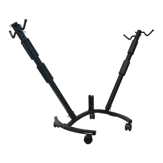
BikeTree™
Part No. B01618
Multi-Use 2-Bike Carrier
PARTS LIST
V-BASE
HORIZONTAL LEG
LOCK NUT
HEX BOLT
WIRE LOCK PIN
SMALL COTTER PIN
WING
UPPER WHEEL CRADLE
LOWER WHEEL CRADLE
RUBBER STRAPS
FOAM CUSHIONS
CAM BUCKLE STRAP
G
M
B
PAGE 1 OF 5
Advertisement
Table of Contents

Related Manuals for Let's Go Aero BikeTree B01618


Summary of Contents for Let's Go Aero BikeTree B01618
- Page 1 BikeTree™ Part No. B01618 Multi-Use 2-Bike Carrier PARTS LIST QTY. DESCRIPTION V-BASE HORIZONTAL LEG LOCK NUT HEX BOLT WIRE LOCK PIN SMALL COTTER PIN WING UPPER WHEEL CRADLE LOWER WHEEL CRADLE RUBBER STRAPS FOAM CUSHIONS CAM BUCKLE STRAP REQUIRED TOOLS: 1/2”...
- Page 2 STEP 1 DETAIL 1 Connect the V-Base [A] to the Horizontal Legs using 13 mm Hex Bolts [D] and 13 mm Lock Nuts [C] as shown [Detail 1]. STEP 2 DETAIL 2 DETAIL 3 WARNING: ALWAYS MAKE SURE EACH CRADLE ASSEMBLY IS HELD IN Attach Adjustable Rubber Straps [K] to the PLACE WITH A SMALL COTTER PIN Upper Wheel Cradles [H] and Lower Wheel...
- Page 3 STEP 3 DETAIL 5 DETAIL 6 Install Wing [G] onto V-Base [A] using Wire Lock Pin [E]. Open wire lock pin [E] as shown in DETAIL 7. Insert wire lock pin [E] through the interior hole at the end of the Wing [G] and out the exterior side of the carrier.
- Page 4 CARRIER INSTALLATION STEP 1: DETAIL 8 DETAIL 9 Install Foam Cushions [L] on ends of Horizontal Legs [B] as shown. [DETAIL 8 & 9] STEP 2: DETAIL 10 DETAIL 11 Center and place the BikeTree inside the Carrier with the Horizontal Legs [B] running perpendicular to the length of the carrier.
- Page 5 ATTACHMENT OF BICYCLES DETAIL 16 BICYCLE WHEEL Reffer to STEP 2 for proper Cradle and Wing Assembly. Lift the bicycle and hang it on the Upper BICYCLE Wheel Cradles [H] with the drive-train RUBBER WHEEL STRAP of the bicycle facing away from the rack for a closer fit.
Need help?
Do you have a question about the BikeTree B01618 and is the answer not in the manual?
Questions and answers