Table of Contents
Advertisement
Quick Links
We have 45,000 LP502030-PCM-NTC-LD-A02554 - EEMB - Lithium Battery Rectangular 3.7V 250mAh Rechargeable in
stock now. Starting at $0.034. This EEMB part is fully warrantied and traceable.
Looking for a discount?
Check out our current promotions!
This coversheet was created by Verical, a division of Arrow Electronics, Inc. ("Verical"). The attached document was created by the part supplier,
not Verical, and is provided strictly 'as is.' Verical, its subsidiaries, affiliates, employees, and agents make no representations or warranties
regarding the attached document and disclaim any liability for the consequences of relying on the information therein. All referenced brands,
product names, service names, and trademarks are the property of their respective owners.
00000005981LF-000
MITX-CORE-HTSNK
EOS Power
ARTESYN EMBEDDED POWER
Buy Now
Buy Now
Give us a call
1-855-837-4225
International: 1-555-555-5555
1-415-281-3866
1-415-281-3866
Arrow Electronics,
Arrow Electronics, Inc
Verical Division
9201 East Dry Creek Road
P.O. Box 740970
Centennial, CO 80112
Los Angeles, CA 90074-0970
Advertisement
Table of Contents

Related Manuals for Artesyn MITX-CORE-820


Summary of Contents for Artesyn MITX-CORE-820
- Page 1 We have 45,000 LP502030-PCM-NTC-LD-A02554 - EEMB - Lithium Battery Rectangular 3.7V 250mAh Rechargeable in stock now. Starting at $0.034. This EEMB part is fully warrantied and traceable. 00000005981LF-000 MITX-CORE-HTSNK EOS Power ARTESYN EMBEDDED POWER Buy Now Buy Now Looking for a discount? Check out our current promotions!
- Page 2 MITX-CORE-820 Installation and Use P/N: 6806800M10H July 2014...
- Page 3 Artesyn reserves the right to revise this document and to make changes from time to time in the content hereof without obligation of Artesyn to notify any person of such revision or changes.
-
Page 4: Table Of Contents
Block Diagram ..............53 MITX-CORE-820 Installation and Use (6806800M10H) - Page 5 4.22 Case Open Header ..............74 MITX-CORE-820 Installation and Use (6806800M10H)
- Page 6 5.5.4 Default Boot Sequence ............96 MITX-CORE-820 Installation and Use (6806800M10H)
- Page 7 6.4.1 Flash with SF100 ............122 MITX-CORE-820 Installation and Use (6806800M10H)
- Page 8 Related Documentation ............. . 129 Artesyn Embedded Technologies - Embedded Computing Documentation ....129...
- Page 9 Contents Contents Contents MITX-CORE-820 Installation and Use (6806800M10H)
- Page 10 MITX-CORE-820 Features Summary ........
- Page 11 Table 6-3 Mapping of Host Interface Registers to the Host Processor ......106 MITX-CORE-820 Installation and Use (6806800M10H)
- Page 12 LED Control Status ............120 Table B-1 Artesyn Embedded Technologies - Embedded Computing Publications ....129 MITX-CORE-820 Installation and Use (6806800M10H)
- Page 13 List of Tables MITX-CORE-820 Installation and Use (6806800M10H)
- Page 14 MITX-CORE-820 Serial Number Location ........37...
- Page 15 List of Figures MITX-CORE-820 Installation and Use (6806800M10H)
-
Page 16: About This Manual
About this Manual Overview of Contents This manual is divided into the following chapters and appendices. Introduction describes the features of the MITX-CORE-820 processors, standard compliances, mechanical data and ordering information. Hardware Preparation and Installation describes the environmental and power ... - Page 17 Hardware Input/Output IEEE Institute of Electrical and Electronics Engineers Inter IC JTAG Joint Test Access Group Kilo Bytes KBAUD Kilo Baud Liquid Crystal Display Light Emitting Diode LVDS Low Voltage Differential Signaling MegaBytes Mbit Megabit MITX-CORE-820 Installation and Use (6806800M10H)
- Page 18 Serial AT Attachment SDRAM Synchronous Dynamic Random Access Memory Surface Mount Technology SODIMM Small-Outline Dual In-line Memory Module Serial Presence Detect SRAM Static Random Access Memory Software Universal Serial Bus Volts Input/Output Voltage Watts Extended Debug Port MITX-CORE-820 Installation and Use (6806800M10H)
- Page 19 Repeated item for example node 1, node 2, ..., node Omission of information from example/command that is not necessary at the time being Ranges, for example: 0..4 means one of the integers 0,1,2,3, and 4 (used in registers) Logical OR MITX-CORE-820 Installation and Use (6806800M10H)
- Page 20 Indicates a hazardous situation which, if not avoided, may result in minor or moderate injury Indicates a property damage message No danger encountered. Pay attention to important information MITX-CORE-820 Installation and Use (6806800M10H)
- Page 21 Components" on page 47 Figure "MITX- CORE-820 Module Components - Continued" on page 48 Editorial edits, changes in information, updates. 6806800M10E September 2011 Updated Figure "MITX-CORE-820 Module Components" on page 47 Updated Ordering Information MITX-CORE-820 Installation and Use (6806800M10H)
-
Page 22: Figure
Consumption Estimation" on page 64 6806800M10C July 2011 Updated Figure "MITX-CORE-820 Module Components" on page Added information on the board CPU specs. 6806800M10B May 2011 Changed marketing name to MITX-CORE- 810/820. Implemented editorial changes. 6806800M10A May 2011 First edition MITX-CORE-820 Installation and Use (6806800M10H) - Page 23 About this Manual About this Manual MITX-CORE-820 Installation and Use (6806800M10H)
-
Page 24: Safety Notes
Artesyn and our suppliers take significant steps to make sure that there are no bent pins on the backplane or connector damage to the boards prior to leaving the factory. Bent pins caused by improper installation or by inserting boards with damaged connectors could void the Artesyn warranty for the backplane or boards. - Page 25 During the course of handling, shipping, and assembly, pins, mounting screws, fans and other items can become loose or damaged. Do not operate a damaged shelf, this can cause damage to devices that interact with it. System Overheating Cooling Vents MITX-CORE-820 Installation and Use (6806800M10H)
- Page 26 Data Loss If the battery does not provide enough power anymore, the RTC is initialized and the data in the NVRAM is lost. Replace the battery before seven years of actual battery use have elapsed. MITX-CORE-820 Installation and Use (6806800M10H)
- Page 27 Do not use a screw driver to remove the battery from its holder. Environment Environmental Damage Improperly disposing of used products may harm the environment. Always dispose of used products according to your country’s legislation and manufacturer’s instructions. MITX-CORE-820 Installation and Use (6806800M10H)
-
Page 28: Sicherheitshinweise
Verletzungen oder Schäden am System zur Folge haben. Artesyn ist darauf bedacht, alle notwendigen Informationen zum Einbau und zum Umgang mit dem System in diesem Handbuch bereit zu stellen. Da es sich jedoch bei dem System um ein komplexes Produkt mit vielfältigen Einsatzmöglichkeiten handelt, können wir die... - Page 29 Während des Transportes, Zusammenbaus und dem Umgang mit dem System können sich Schrauben, Lüfter oder andere Teile lösen oder beschädigt werden. Nehmen Sie ein beschädigtes System nicht in Betrieb. Sonst können andere Einrichtungen, die mit dem System kommunizieren, beschädigt werden. Überhitzung des Systems Lüftungsöffnungen MITX-CORE-820 Installation and Use (6806800M10H)
- Page 30 Um Verletzungen durch Verbrennung zu vermeiden, berühren Sie während der Arbeit keine Komponenten oder Kühlkörper auf dem Produkt. Fassen Sie das Produkt an den Handles und der Frontblende an, wenn Sie es aus dem System herausnehmen. MITX-CORE-820 Installation and Use (6806800M10H)
- Page 31 Benutzen Sie keinesfalls einen Schraubendreher um die Batterie aus der Halterung zu nehmen. Environment Umweltverschmutzung Falsche Entsorgung der Produkte schadet der Umwelt. Entsorgen Sie alte Produkte gemäß der in Ihrem Land gültigen Gesetzgebung und den Empfehlungen des Herstellers. MITX-CORE-820 Installation and Use (6806800M10H)
-
Page 32: Introduction
Chapter 1 Introduction Overview MITX-CORE-820 is an Artesyn designed Mini-ITX motherboard based on Intel® 6 Series Chipset supporting Intel® Sandy Bridge Mobile rPGA Quad/Dual core processors. Features The following table lists the features of the MITX-CORE-820 motherboard. Table 1-1 MITX-CORE-820 Features Summary... - Page 33 Introduction Table 1-1 MITX-CORE-820 Features Summary (continued) Function Features Board size Mini-ITX 170 mm x 170 mm form factor 10 Layers PCB Serial ATA 2 SATA 6G ports and 2 SATA 3G ports EC/Thermal Sensor Voltage, temperature and fan speed control...
-
Page 34: Standard Compliances
Introduction Table 1-1 MITX-CORE-820 Features Summary (continued) Function Features Industrial Standard ACPI 4.0a PCI Express Gen2 SMbus Version2.0 Universal Host Controller Interface Revision1.1(UHCI) Enhanced host Controller Interface specification for Universal Serial bus Revision1.0(EHCI) Serial ATA specification revision 3.0 ... - Page 35 Technology Equipment. AS/NZS CISPR 22 Class B (Australia/New Limits and methods of measurement of radio Zealand) disturbance characteristics of Information Technology Equipment. VCCI Class B (Japan) Voluntary Control Council for Interference by Information Technology Equipment. MITX-CORE-820 Installation and Use (6806800M10H)
-
Page 36: Figure 1-1 Declaration Of Conformity
Introduction The following figure is the copy of Declaration of Conformity for MITX-CORE-820: Figure 1-1 Declaration of Conformity C Declaration of Conformity According to EN 17050-1:2004 Manufacturer’s Name: Artesyn Embedded Technologies Embedded Computing Manufacturer’s Address: Zhongshan General Carton Box Factory Co. Ltd. No 62, Qi... -
Page 37: Mechanical Specifications
Introduction Mechanical Specifications Figure 1-2 MITX-CORE-820 Mechanical Data (Top View) MITX-CORE-820 Installation and Use (6806800M10H) -
Page 38: Board Identification
Introduction Figure 1-3 MITX-CORE-820 Mechanical Data (Side View) Board Identification This section shows the serial number and its location on the board. Figure 1-4 MITX-CORE-820 Serial Number Location MITX-CORE-820 Installation and Use (6806800M10H) -
Page 39: Ordering Information
Ordering Information Use the following order numbers when ordering board variants or board accessories. Some accessories are not available for order through Artesyn. These iclude the CPU or processor cooler/heat sink, and SODIMM DDR3 MEM. To order the processor, please contact Intel©... -
Page 40: Hardware Preparation And Installation
Chapter 2 Hardware Preparation and Installation Environmental and Power Requirements The following environmental and power requirements are applicable to the MITX-CORE-820. 2.1.1 Environmental Requirements The following table lists the environmental requirements that the board must meet when operated in your particular system configuration. -
Page 41: Power Requirements
2.1.2 Power Requirements The MITX-CORE-820 is designed to receive power from an input power connector that accepts +12V or +14.4V~+19.5V in the back-panel IO region, or from a 4-pin +12V ATX power connector. When a charger board is used, the power can be supplied using a 4-pin +12 V ATX power connector from the adapter or battery connected to charger board. -
Page 42: Unpacking And Inspecting The Board
1. Verify that you have received all items of your shipment. Quick Start Guide and Safety Notes summary Motherboard Two SATA power Cables Two SATA data cables Driver CD I/O Shield MITX-CORE-820 Installation and Use (6806800M10H) -
Page 43: Preparing The Installation Environment
Do not exert too much force, or insert or remove the components forcibly. Avoid damage to the components or plug-ins. Confirm the feasibility of the of operation MITX-CORE-820 Installation and Use (6806800M10H) - Page 44 There are available spare parts of the components to be installed or replaced in the equipment warehouse. When the available spare parts are lacking, contact Artesyn Embedded Technologies for help in time. For details on how to get help from Artesyn Embedded Technologies, visit http://www.artesyn.com/computing/...
-
Page 45: Memory Module Installation
Hardware Preparation and Installation Memory Module Installation When installing or replacing the module, pay attention to the following: The MITX-CORE-820 supports up to 16GB dual-channel, non-ECC, unbuffered DDR3 SO- DIMM. The SO-DIMMs must have the same sizes, frequencies, types and technologies, physical ... -
Page 46: Processor Cooler Installation
Make sure the glue layer of the backplate does not touch any other part of the motherboard. 5. Place the cooler on the backplate and secure it with the provided screws. 6. Plug the fan header into the fan connector on the motherboard. MITX-CORE-820 Installation and Use (6806800M10H) - Page 47 Hardware Preparation and Installation Removing the Processor Cooler 1. Wear the ESD-preventive wrist strap. 2. Disconnect the fan header from the fan connector on the motherboard. Loosen the screws to remove the processor cooler from the backplate. MITX-CORE-820 Installation and Use (6806800M10H)
-
Page 48: Controls, Leds And Connectors
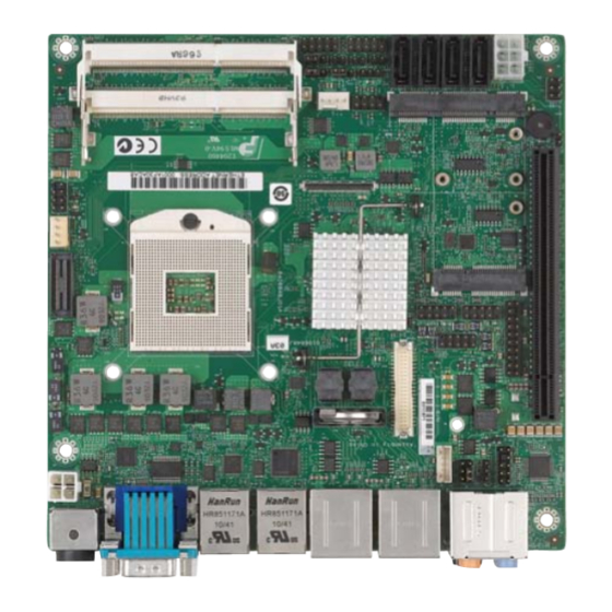
Chapter 3 Controls, LEDs and Connectors Board Layout The module components of the MITX-CORE-820 are shown in detail in Figure 3-1and Figure 3-2. Figure 3-1 MITX-CORE-820 Module Components MITX-CORE-820 Installation and Use (6806800M10H) -
Page 49: Figure 3-2 Mitx-Core-820 Module Components - Continued
Controls, LEDs and Connectors Figure 3-2 MITX-CORE-820 Module Components - Continued MITX-CORE-820 Installation and Use (6806800M10H) -
Page 50: Connector Definitions
Controls, LEDs and Connectors Connector Definitions The following table lists the connectors and headers located on the MITX-CORE-820 motherboard along with a link to each connector's associated pin out definition document. Connectors or headers are defined in the following sections. -
Page 51: Led Controls
LED Controls The MITX-CORE-820 has one green LED and one red LED to indicate the charging and discharging status. Only a charging board is needed for battery management as the LED is fully controlled by the EC. -
Page 52: Rear I/O Connectors
Controls, LEDs and Connectors Rear I/O Connectors Figure 3-3 Rear I/O Connectors MITX-CORE-820 Installation and Use (6806800M10H) - Page 53 Controls, LEDs and Connectors MITX-CORE-820 Installation and Use (6806800M10H)
-
Page 54: Functional Description
This engineering specification defines a standard Mini-ITX motherboard. The board supports a single DC-Jack or ATX 4-pin power input and smart battery power input. The board communicates with a charger board with the smart battery input through a header on the motherboard. Figure 4-1 Block Diagram MITX-CORE-820 Installation and Use (6806800M10H) -
Page 55: Processor
The board also provides the option to support one 35 W 2-core Core i5 Celeron Intel Sandy Bridge-Mobile PGA Embedded processor. Motherboard Clock Diagram The MITX-CORE-820 implements full integrated clocking mode as the only platform clock solution. Figure 4-2... -
Page 56: Chipset
Intel © Remote PC Assist Technology - Reactive System Memory The MITX-CORE-820 supports one DDR3 1066MT/s/1333MT/s/1600MT/s SODIMM per channel, for a total of 2 DDR3 SODIMMs. Maximum memory capacity is 16 GB (8 GB per SODIMM) using 2 GB technology. Minimum capacity is a single 1 GB SODIMM using 1 GB technology. -
Page 57: Video
4.6.1 LVDS The MITX-CORE-820 supports dual-channel LVDS on pipe A of the Integrated Graphics Controller. The Intel 6 Series chipset supports up to 24-bit color per pixel, so the design can support both 18-bit and 24-bit LCD panels utilizing different cables. -
Page 58: Vga
Functional Description The design implements a separate LVDS and Backlight Inverter connectors located on the board. The connectors follow the common parts used on Artesyn products. Table 4-3 LVDS Panel VDD Selector (P29) Jumper setting (Jumper:P29) Configuration P29 (2-4) +3.3 V (Default) -
Page 59: Display Port
Port Spec v1.1. The interface can support 1, 2 or 4 lanes eDP with up to 2.7 Gb/s per lane. Table 4-5 eDP Connector (J15) Pin# Signal Name Pin# Signal Name VDD_LVDS DP_TXN0 VDD_LVDS DP_TXP0 VDD_LVDS VDD_LVDS EMB_AUXP VDD_LVDS EMB_AUXN V3.3S V12S EMB_HPD DP_TXN3 DP_TXP3 L_BKLT_CTRL L_BKLT_EN DP_TXN2 V12S DP_TXP2 V3.3S MITX-CORE-820 Installation and Use (6806800M10H) -
Page 60: Pci Express
SMB_THRM_DATA PCI Express The MITX-CORE-820 has one x16 5G PCI-Express slot which supports graphics cards up to 75 W in power. The position of the PCI-Express slot follows the Mini-ITX Addendum Version 1.1 of the microATX Motherboard Interface Specification Version 1.2. - Page 61 Signal LAN1_MDI0P LAN1_MDI0N LAN1_MDI1P LAN1_MDI1N +VCT_LAN_C +VCT_LAN_C LAN1_MDI2P LAN1_MDI2N LAN1_MDI3P LAN1_MDI3N LAN1_LED_LNK#_ACT LAN1_LED_LNK#_ACT_R LAN1_LED_1000# LAN1_LED_100# Table 4-7 LAN2 Connector Signal Signal LAN2_MDI0P LAN2_MDI0N LAN2_MDI1P LAN2_MDI1N VCC1V8_LAN_C VCC1V8_LAN_C LAN2_MDI2P LAN2_MDI2N LAN2_MDI3P LAN2_MDI3N LAN2_LED_LNK#_ACT LAN2_LED_LNK#_ACT_R LAN2_LED_1000# LAN2_LED_100# MITX-CORE-820 Installation and Use (6806800M10H)
-
Page 62: Wifi/Wimax
4.10 Storage The MITX-CORE-820 supports two SATA 3G and two SATA 6G ports with standard vertical data connectors. The SATA power connector provides sufficient +3.3V, +5V, +12V power to accommodate both SSD and rotating-media drives of 1.8", 2.5" and 3.5" sizes. The MITX-CORE- 820 supports RAID 0, 1, 5, 10 across all SATA interfaces (MITX-CORE-820 only). -
Page 63: Usb 2.0
Functional Description 4.11 USB 2.0 The MITX-CORE-820 implements four standard type A connectors located in the backpanel I/O region of the motherboard. In addition, three standard.100"x.100" 10-pin, dual-row header supporting dual-ports are located on the motherboard (see Table 4-3 for pinout). The P25 of the 10-pin headers provides mechanical support for retention standoff to support Intel®... -
Page 64: Power Supplies
Functional Description 4.12 Power Supplies The MITX-CORE-820 receives power from an input power connector that accepts +12 V or +14.4 V~+19.5 V in the back-panel IO region, or from a 4-pin +12 V ATX power connector. When a charger board is used, the power can be supplied using a 4-pin +12 V ATX power connector from the adapter or battery connected to charger board. -
Page 65: Power Consumption
The power sequencing meets the PCH power sequencing requirements. 4.12.3 Power Management The MITX-CORE-820 design is ACPI 4.0a compliant. System power states S0 (Power-on), S3 (Suspend to RAM), S4 (Suspend to Disk), and S5 (Soft Off) is supported. Deep Sleep Sx is also supported after the option in BIOS setup is enabled. -
Page 66: Power Measurement
Functional Description 4.12.4 Power Measurement The MITX-CORE-820 design provides the ability to measure power consumption on DC-IN supply rails. 4.13 Embedded Controller The MITX-CORE-820 design implements a Nuvoton NPCE791C embedded controller. The following sections list the functionality of the embedded controller, or EC. -
Page 67: Fan Header
Functional Description 4.13.3 Fan Header The MITX-CORE-820 design provides one 4-wire fan header on the motherboard planar for the CPU fan and one 4-wire fan header on the motherboard planar for the system. Fans support fan tachometer input and PWM fan speed control. The design uses 4-pin locking connector equivalent to Molex 47053-1000. -
Page 68: Debug Header
EC_RDY# 4.13.6 Charge Board Interface The MITX-CORE-820 design supports a charge board interface from the EC. There are two SMBUS communicating with the Smart Charger and the Smart Battery respectively. EC also accepts ACAV (AC_Present) and monitors charge/discharge current information from the charge board. -
Page 69: Smbus Architecture
Functional Description 4.14 SMBUS Architecture Figure 4-10 SMBUS Architecture MITX-CORE-820 Installation and Use (6806800M10H) -
Page 70: Audio
Functional Description 4.15 Audio The MITX-CORE-820 design supports a minimum 7.1-channel HD Audio CODEC with the following connectivity: Rear IO – Stereo Line In – Stereo Line Out (Front Speakers) – Mic In – Stereo Rear Speakers – Middle/Sub Speaker –... -
Page 71: Table 4-19 Front Panel Audio Header (P9) Description
Functional Description Figure 4-11 Rear Panel Audio Jack Table 4-19 Front Panel Audio Header (P9) Description Signal Signal MIC2_L MIC2_R FP_AUDIO_PSNT# LOUT2_R MIC2_JD LOUT2_L LOUT2_JD Figure 4-12 Front Panel Audio Header (P9) MITX-CORE-820 Installation and Use (6806800M10H) -
Page 72: Watchdog Timer
This function is optional as per user’s request. 4.16 Watchdog Timer The MITX-CORE-820 implements a two-stage watchdog timer (WDT), such as the one integrated with PCH, with a programmable timeout (one second to ten minutes minimum) and the ability for software to enable and disable. The BIOS disables the device at boot, and the software will re-enable when watchdog application loads. -
Page 73: Spi Flash
Functional Description 4.18 SPI Flash The MITX-CORE-820 design does not support a firmware hub. Instead, it has two SPI flash devices (minimum 8 MB each) that provides flash support for the system BIOS, Intel® WG82579LM LAN image/MAC address and the manageability engine/AMT firmware. The SPI flash devices can be socketed during debugging. -
Page 74: Tpm/Port 80 Interface
TPM header. This is not a defect on the motherboard. Table 4-23 TPM/Port80 Header (P3) Definition Signal Signal CLK_PCI_TPM LPC_FRAME# TPM_RST_N +V5S LPC_AD3 LPC_AD2 +V3.3S LPC_AD1 LPC_AD0 SMB_CLK_S SMB_DATA_S +V3.3A INT_SERIRQ TPM_CLKRUN_N PM_SUS_STAT# PCH_DRQ#0 Figure 4-14 TPM/Port80 Header (P3) MITX-CORE-820 Installation and Use (6806800M10H) -
Page 75: On Board Led Interface
Table 4-24 Charge LED 1 (P31) Signal +V3.3A_KBC C_PWM Table 4-25 Charge LED 2 (P34) Signal +V3.3A_KBC D_PWM 4.22 Case Open Header Case open header is reserved for customized application. Table 4-26 Case Open Header (P27) Signal SM_INTRUDER# MITX-CORE-820 Installation and Use (6806800M10H) -
Page 76: Internal Graphics Disable
(Jumper:P33) Configuration P33 (1-2) NC (DEFAULT) P33 (2-3) I-GRAPHICS DISABLE 4.24 User GPIO Header The MITX-CORE-820 supports a GPIO header with support for 4xGPI and 4xGPO & ground(s). Table 4-28 User GPIO Header (P28) Signal Signal PCA9557_GPO0 PCA9557_GPI0 PCA9557_GPO1 PCA9557_GPI1... -
Page 77: Wake Events
Functional Description 4.26 Wake Events The MITX-CORE-820 supports a wake up signal header, that can cause the platform to move from S3 sleep state to S0. Table 4-29 Wake Up Header (P18) Signal +V5A WAKEUP_GPI 4.27 Manageability The Gala MITX-CORE-820 supports Intel AMT 7.0. design and provides support for M0, M1 and M-off manageability states. -
Page 78: Bios
If you exit setup without saving any changes, the boot process continues with the search for a boot device. If the changes are saved, the motherboard loads the new settings and resets, re-starting the entire boot process. MITX-CORE-820 Installation and Use (6806800M10H) -
Page 79: Setup Utility
Description ENTER The Enter key allows you to select an option to edit its value or access a sub menu. Left/Right The Left and Right <Arrow> keys allows you to select a screen or menu. MITX-CORE-820 Installation and Use (6806800M10H) - Page 80 When you are in sub-menu, <Esc> allows you to exit to the upper menu. Function keys When other function keys become available, they are displayed at the right of the screen along with their intended function. MITX-CORE-820 Installation and Use (6806800M10H)
-
Page 81: Main Menu
There is no default value. System Information Shows the BIOS version, CPU type, memory type and size, and so on. See Table "System Information Field Description" on page MITX-CORE-820 Installation and Use (6806800M10H) -
Page 82: System Information
Channel A slot0 memory size and type Memory Channel B Slot0 Channel B slot0 memory size and type 5.4.1.2 Boot Features Table 5-5 Boot Features Field Description Field Description NumLock Selects Power-on state for NumLock. MITX-CORE-820 Installation and Use (6806800M10H) -
Page 83: Advanced Menu
Boot Configuration Sets boot configuration. See Boot Configuration. Processor Configuration Sets CPU configuration. See Processor Configuration. Peripheral Configuration Sets system peripheral configuration. See Processor Power Management. HDD Configuration Sets hard drive and controller configuration. See Configuration. MITX-CORE-820 Installation and Use (6806800M10H) -
Page 84: Boot Configuration
When enabled, it forces the display adapter to switch the video mode to Text Mode 3 at the end of POST for legacy boot mode. RPB Terminal Type Sets terminal type of RPB. RPB Baudrate Sets baudrate of RPB. MITX-CORE-820 Installation and Use (6806800M10H) -
Page 85: Processor Configuration
Enables processor Turbo Mode. EMTTM must also be enabled. C-States Enables processor idle power saving states (C-States). C3-State Enables processor idle power saving C3 state. C6-State Enables processor idle power saving C6 state. C7-State Enables processor idle power saving C7 state. MITX-CORE-820 Installation and Use (6806800M10H) -
Page 86: Peripheral Configuration
Displays the identity of the device attached. Serial ATA Port 2 / Hard Disk 4 Displays the identity of the device attached. Serial ATA Port 3 / Hard Disk 5 Displays the identity of the device attached. MITX-CORE-820 Installation and Use (6806800M10H) -
Page 87: Memory Configuration
Press Enter to bring up the Intel(R) VT for directed I/O (VT-d) (VT-d) configuration menu. See Intel(R) VT for Directed I/O (VT-d). Graphics Configuration Press Enter to access the graphics configuration menu. See Graphics Configuration. MITX-CORE-820 Installation and Use (6806800M10H) -
Page 88: Table 5-15 Intel(R) Vt For Directed I/O (Vt-D) Field Description
This has no effect if external graphics are present. DVMT Total Gfx Mem DVMT5.0 DVMT graphics memory size. This has no effect if external graphics are present. GT Turbo Mode Control Enables/Disables GT Turbo Mode Control. IGD Configuration IGD Configuration. See Configuration. MITX-CORE-820 Installation and Use (6806800M10H) -
Page 89: South Bridge Configuration
GPI13 high or low polarity setting. SB PCI Express Config Sets PCI express configuration. See SB PCI Express Config. SB USB Config Sets USB configuration. See SB USB Configuration. SB Azalia Config Sets HD Audio configuration. See SB Azalia Configuration. MITX-CORE-820 Installation and Use (6806800M10H) -
Page 90: Table 5-19 Sb Pci Express Configuration Field Description
Controls the USB EHCI (USB 2.0) functions. EHCI2 Controls the USB EHCI (USB 2.0) functions. USB Ports Per-Port Disabled Controls each of the USB ports (0~13) enable/disable. Control USB Port Enables/Disables the USB port. #0/1/2/3/4/5/6/7/8/9/10/11/ 12/13 Enable/Disable MITX-CORE-820 Installation and Use (6806800M10H) -
Page 91: Network Configuration
SPI device. Intel AMT Hot Key Enables or Disables Intel® AMT Hot-Key during POST to enter MEBX setup. Intel AMT Setup Prompt Enables/Disables Intel® AMT Setup Prompt to wait for hot-key to enter setup. MITX-CORE-820 Installation and Use (6806800M10H) -
Page 92: Me Configuration
USB-R Feature Enables/Disables USB-R. 5.4.2.11 ME Configuration Table 5-25 ME Configuration Field Description Field Description ME FW Version Intel® Management Engine firmware version. ME Firmware Intel® Management Engine firmware state. Intel ME Enables/Disables Intel® Management Engine. MITX-CORE-820 Installation and Use (6806800M10H) -
Page 93: Security Menu
BIOS 5.4.3 Security Menu Figure 5-3 Security Menu 5.4.3.1 Trusted Platform Module (TPM) Configuration Table 5-26 TPM Configuration Field Description Field Description Current TPM State Current TPM State MITX-CORE-820 Installation and Use (6806800M10H) -
Page 94: Boot Menu
BIOS Table 5-26 TPM Configuration Field Description Field Description Change TPM States Changes TPM state. Note: Most TPM options require TPM to be Enabled to take effect. 5.4.4 Boot Menu Figure 5-4 Boot Menu MITX-CORE-820 Installation and Use (6806800M10H) -
Page 95: Exit Menu
Equal to ESC, never save changes, then exit setup configure driver. Finally resets the system automatically. Load Setup Defaults Equal to F9, Load standard default values. Load Optimized Defaults Load settings for optimized boot time and system performance. MITX-CORE-820 Installation and Use (6806800M10H) -
Page 96: Miscellaneous
Save Changes Save all changes of all menus, but do not reset system. Miscellaneous 5.5.1 Supported OS List The following operating systems are supported by MITX-CORE-820. Microsoft Windows XP Microsoft Window 7 Microsoft Embedded 7 Standard ... -
Page 97: Acpi Wake Up Support Matrix
Internal Shell - UEFI Shell PXE Network Boot - PCI Express Ethernet Controller BIOS Status Codes The following tables list the BIOS status codes applicable to the MITX-CORE-820. 5.6.1 Status Code Ranges Table 5-30 Status Code Ranges Status Code Range... -
Page 98: Standard Status Codes
POSTCODE_CC_CPU_IO 0x27 POSTCODE_CC_BOOT_SCRIPT 0x28 POSTCODE_CC_STATUS_CODE 0x29 POSTCODE_CC_DATA_HUB 0x2A POSTCODE_CC_HII_DATABASE 0x2B POSTCODE_CC_RESET 0x2C POSTCODE_CC_METRONOME 0x2D POSTCODE_CC_INTERRUPT_CONTROLLER 0x2E POSTCODE_CC_DIAGNOSTIC_SUMMARY 0x2F POSTCODE_CC_SMBIOS 0x30 POSTCODE_CC_SMM_COMMUNICATION 0x31 POSTCODE_CC_SMM_RUNTIME 0x32 POSTCODE_CC_SMM_SERVICES 0x33 POSTCODE_CC_FIRMWARE_DEVICE 0x34 POSTCODE_CC_CAPSULE_SERVICES 0x35 POSTCODE_CC_MONOTONIC_COUNTER 0x36 POSTCODE_CC_SMBIOS_EVENT_LOG 0x37 POSTCODE_CC_RTC MITX-CORE-820 Installation and Use (6806800M10H) -
Page 99: Table 5-32 Progress Status Codes
Table 5-33 Architectural Status Codes Status Code Code Symbol 0xE0 POSTCODE_PC_SEC_ENTRY 0xE1 POSTCODE_PC_SEC_EXIT 0xE2 POSTCODE_PC_PEI_ENTRY 0xE3 POSTCODE_PC_PEI_EXIT 0xE4 POSTCODE_PC_IPL_DXE 0xE5 POSTCODE_PC_IPL_S3 0xE6 POSTCODE_PC_S3_OS 0xE7 POSTCODE_PC_IPL_RECOVERY 0xE8 POSTCODE_PC_IPL_EXIT 0xE9 POSTCODE_PC_DXE_ENTRY 0xEA POSTCODE_PC_DXE_EXIT 0xEB POSTCODE_EC_PEI_MEMORY 0xEC POSTCODE_EC_PEI_IPL MITX-CORE-820 Installation and Use (6806800M10H) -
Page 100: Accessing The Mebx Setup Menu
2. Get the BIOS flash tool Pflash.exe from the BIOS vendor. 3. Copy the Pflash.exe and BIOS ROM file into the USB thumb drive. 4. Power on the MITX-CORE-820 board. 5. Press <F2> to enter the BIOS setup menu. 6. Select the USB thumb drive as the first boot device. - Page 101 BIOS MITX-CORE-820 Installation and Use (6806800M10H)
-
Page 102: Firmware
PS/2 mice. Options are also available for battery charging and monitoring firmware. EC firmware is also fully functional in ACPI(SCI) or legacy environments. In the MITX-CORE-820, the NPCE791C from Nuvoton was selected as the EC silicon. It provides the power sequence controller, PS2 KB/MS interface, battery management, thermal/temperature/fan speed control, serial port and LED controller. -
Page 103: System Bios Porting
This table shows the LDN values of the NPCE791x functional blocks. Any value not listed is set as reserved. Table 6-1 LDN Values Functional Block Serial Port 1 Mobile System Wake-Up Control KBC - Mouse Interface KBC - Keyboard interface Shared Memory MITX-CORE-820 Installation and Use (6806800M10H) - Page 104 However, the device control and device configuration registers are replicated over the banks of each logical device. Two-dimensional indexing is used to access a specific register in a specific bank: the LDN register which selects the bank; and the index MITX-CORE-820 Installation and Use (6806800M10H)
-
Page 105: Figure 6-2 Structure Of Standard Configuration Register
30h or higher actually accesses the logical device configuration registers. These are currently pointed to by the index register within the logical device currently selected by the LDN register Figure 6-2 Structure of Standard Configuration Register MITX-CORE-820 Installation and Use (6806800M10H) -
Page 106: Standard Logical Device Configuration Register
70h DMA Channel Select 0 Indicates selected DMA channel for DMA 0 or DMA 1 of the logical device. DMA Channel Select 1 F0h - FFh Device Specific Logical Device Special (vendor-defined) configuration Configuration options. MITX-CORE-820 Installation and Use (6806800M10H) -
Page 107: Kbc Address To Host Processor
Upon detecting this bit being set, the system should query the SCI event queue to obtain the SCI ID number. Receiving and completing the EC standard commands will not cause the SCI bit to be set. MITX-CORE-820 Installation and Use (6806800M10H) -
Page 108: Ec Command Register
Write operation for an internal register in EC space EC Burst Enable Enable EC burst operation mode EC Burst Disable Disable EC burst operation mode EC Query Query the SCI event queue Others Firmware Command No responded from hardware EC. MITX-CORE-820 Installation and Use (6806800M10H) -
Page 109: Ec Command Program Sequence
Write EC_CMD with 84h Wait SCI for OBF=1 Read EC_DAT with SCI ID number 6.2.9 EC Space Definition Table 6-7 EC Space Definition Table Offset Length (Bytes) Description 0x00 Thermal Version 0x01 Maximum Fan Level Support MITX-CORE-820 Installation and Use (6806800M10H) - Page 110 0x1C System Level 3 Trip 0x1D System Level 3 Hysteresis 0x1E System Level 4 Trip 0x1F System Level 4 Hysteresis 0x20 System Level 5 Trip 0x21 System Level 5 Hysteresis 0x22 System Level 6 Trip MITX-CORE-820 Installation and Use (6806800M10H)
- Page 111 0x37 Core1 Level 4 Hysteresis 0x38 Core1 Level 5 Trip 0x39 Core1 Level 5 Hysteresis 0x3A Core1 Level 6 Trip 0x3B Core1 Level 6 Hysteresis 0x3C Core2 Level 1 Trip 0x3D Core2 Level 1 Hysteresis MITX-CORE-820 Installation and Use (6806800M10H)
- Page 112 Fan speed to be set 0x50 Throttling State 0x51 System Configuration Byte 0x52 Device Status Byte 0x90 Power Status 0x91 Reserved 0x92 Battery Voltage 0x94 Battery Current 0x96 Battery Relative State of Charge 0x98 Battery Remaining capacity MITX-CORE-820 Installation and Use (6806800M10H)
-
Page 113: Event List
Table 6-8 Q Event List Q Event ID Description _Q30 Real AC Insertion/Removal Event _Q31 Real Battery Insertion/Removal Event _Q32 Real Battery Low Event _Q33 Real Battery Very Low Event _Q34 CPU Throttling On/Off Event _Q36 Thermal Trip Event MITX-CORE-820 Installation and Use (6806800M10H) -
Page 114: Os Driver Support
The ACPI-compliant operating systems provide the embedded controller driver and battery driver. EC Firmware Porting 6.3.1 Power Sequence Control The hardware provides the power sequencing table. The following tables should be filled to implement the platform’s various power sequences. MITX-CORE-820 Installation and Use (6806800M10H) - Page 115 | LOW, 00, 0x00 | INPUT }, /* D - */ {UNUSED_PIN | LOW, 00, 0x00 | INPUT }, /* E - */ {UNUSED_PIN | LOW, 00, 0x00 | INPUT } /* F - */ MITX-CORE-820 Installation and Use (6806800M10H)
- Page 116 | LOW, 00, 0x00 | OUTPUT}, /* 6 - Reserved */ {UNUSED_PIN | LOW, 00, 0x00 | INPUT }, /* 7 - Reserved */ {UNUSED_PIN | LOW, 00, 0x00 | OUTPUT} /* 8 - Reserved */ MITX-CORE-820 Installation and Use (6806800M10H)
-
Page 117: Peci
/* 8 - Reserved */ 6.3.2 PECI EC should be able to read the CPU temperatures through the PECI interface. A PECI initialization and a PECI polling function should be implemented. Samples of this include OEM_PECI_Init(void) and OEM_PECI_Polling(void). MITX-CORE-820 Installation and Use (6806800M10H) - Page 118 /* Initialize the PECI module /*--------------------------------------------------------------*/ PECI_Init(PECI_CallBack, 0); /*--------------------------------------------------------------*/ /* Configure PECI domain and client address /*--------------------------------------------------------------*/ PECI_SetDomain(PECI_DOMAIN); PECI_SetAddress(PECI_CLIENT_ADDR); peci_client_available = 0; void OEM_PECI_Polling(void) if(!(REG_READ(PECI_CTL_STS) & 0x01)) /*If PECI not busy*/ if(peci_client_available) PECI_GetTemp(); else PECI_Ping(); MITX-CORE-820 Installation and Use (6806800M10H)
-
Page 119: Thermal & Fan Speed Control
Battery Information - Charging & Discharging Control The hardware selects a battery, so the EC firmware could report the battery information and write the code for charging and discharging. There are five charging states: Wake-up charging Pre-charging MITX-CORE-820 Installation and Use (6806800M10H) -
Page 120: Voltage Monitor
6.3.5 Voltage Monitor The MITX-CORE-820 uses the EC pins to monitor the following voltages: +5V, +3.3V, +1.5V, +1.5V. EC should be able to read the voltage and if possible, should have a method and pass the value to BIOS or EAPI application. -
Page 121: Wake Up Requirement
The PS2 kb/mouse supports wake up from sleep state, in both S1/S3, but not S5. 6.3.7 LEDs Control The MITX-CORE-820 has a green LED and a red LED to indicate the charging or discharging status Table 6-10 LED Control Status... -
Page 122: Ps2 Interface & Device Configuration
PS2 Interface & Device Configuration NPCE791x provides three PS/2 channels including channel 1, channel 2 and channel 3. For the MITX-CORE-820, the channel 3 is for PS2 mouse, the channel 2 is for PS2 keyboard and the channel 1 is not used. -
Page 123: Ec Firmware Flash
EC Firmware Flash 6.4.1 Flash with SF100 The MITX-CORE-820 uses the Nuvoton W25Q80 as a flash device. The EC firmware is stored in the SPI flash part. The SF100 can be used to flash the firmware into the flash part. 6.4.2 Flash with ECDT Nuvoton provides a USB to the JTAG board. -
Page 124: Jtag Interface
Firmware 6.5.2 JTAG Interface The MITX-CORE-820 provides JTAG interface for the NPCE791x silicon. Connect the USB to the JTAG board with the Gala board through the ECDT utility to debug the EC firmware. MITX-CORE-820 Installation and Use (6806800M10H) - Page 125 Firmware MITX-CORE-820 Installation and Use (6806800M10H)
-
Page 126: Replacing The Battery
Appendix A Replacing the Battery Overview The board contains an on-board Lithium coin battery BR2032. Its location is show in the following figure: Figure A-1 Battery Location MITX-CORE-820 Installation and Use (6806800M10H) -
Page 127: Procedure Description
Replacing the Battery The battery provides data retention of one year summing up all periods of actual data use. Artesyn therefore assumes that there usually is no need to exchange the battery except, for example, in case of long-term spare part handling. - Page 128 1. Gently lift the battery retaining tab. 2. Remove the battery. Install the new battery in such a way that the plus sign marked on it is face up. MITX-CORE-820 Installation and Use (6806800M10H)
- Page 129 Replacing the Battery MITX-CORE-820 Installation and Use (6806800M10H)
-
Page 130: Related Documentation
The publications listed below are referenced in this manual. You can obtain electronic copies of Artesyn Embedded Technologies - Embedded Computing publications by contacting your local Artesyn sales office. For released products, you can also visit our Web site for the latest copies of our product documentation. - Page 131 Related Documentation MITX-CORE-820 Installation and Use (6806800M10H)
- Page 133 Artesyn Embedded Technologies, Artesyn and the Artesyn Embedded Technologies logo are trademarks and service marks of Artesyn Embedded Technologies, Inc. All other product or service names are the property of their respective owners. © 2014 Artesyn Embedded Technologies, Inc.
Need help?
Do you have a question about the MITX-CORE-820 and is the answer not in the manual?
Questions and answers