Table of Contents
Advertisement
Quick Links
Advertisement
Table of Contents

Related Manuals for Artesyn BajaPPC-750


Summary of Contents for Artesyn BajaPPC-750
- Page 1 SECURE ASSET SOLUTIONS Artisan Scientific Corporation / Artisan Technology Group is not an authorized distributor of Artesyn Embedded Technologies, Inc. or Artesyn products. Artesyn Embedded Technologies® is a trademark of Artesyn Embedded Technologies, Inc. and is used for identification purposes only.
- Page 2 BajaPPC-750 PowerPC-Based, Single-Board Computer User’s Manual May 2002...
- Page 3 Artesyn Communication Products 8310 Excelsior Dr. Madison, WI 53717 Web Site: www.artesyncp.com Sales: (800) 356-9602 Technical Support: (800) 327-1251 BajaPPC-750 User’s Manual—Artesyn Part Number: 0002M621-15...
- Page 4 BajaPPC-750 PowerPC-Based, Single-Board Computer User’s Manual May 2002...
- Page 5 PRODUCTS DOES NOT ASSUME ANY LIABILITY ARISING OUT OF USE OR OTHER APPLICATION OF ANY PRODUCT, CIRCUIT, OR PROGRAM DESCRIBED HEREIN. This document does not convey any license under Artesyn Communica- tion Products patents or the rights of others. Artesyn and the Artesyn logo are registered trademarks of Artesyn Technologies and are used by Artesyn Communication Products under licence from Artesyn Technologies.
- Page 6 Regulatory Agency Warnings & Notices The Artesyn BajaPPC-750 is certified by the Federal Communications Commission (FCC) according to Title 47 of the Code of Federal Regulations, Part 15. The following informa- tion is provided as required by this agency. FCC Rules and Regulations – Part 15 This equipment has been tested and found to comply with the limits for a Class B digital device, pursuant to part 15 of the FCC Rules.
-
Page 8: Table Of Contents
2.2 BajaPPC-750 Circuit Board ........ - Page 9 6.3.2 Data Transfers ........... . .6-17 BajaPPC-750: Contents...
- Page 10 6.4 VMEbus Slave Interface ............6-17 6.4.1 Slave Mapping Example.
- Page 11 10.5.14 um.............10-22 BajaPPC-750: Contents...
- Page 12 10.5.15 writemem ............10-22 10.5.16 writestr .
- Page 13 10.14 BajaPPC-750-Specific Functions........
- Page 14 Figures Figure 1-1. General System Block Diagram ..........1-3 Figure 1-2.
- Page 15 BajaPPC-750 Interrupt Status ........
-
Page 16: Register Map
Register Map 9-1. Counter/Timer Status, CTSR .........9-2 Register Map 9-2. - Page 17 Table 4-4. SDRAM Access Time Required for the BajaPPC-750 ......4-5 Table 4-5.
- Page 18 Table 7-3. Default Ethernet Boot Device Selection (JP1) ........7-4 Table 7-4.
- Page 19 BajaPPC-750: Contents...
-
Page 20: Overview
MVME712M transition module. 1.1 Components and Features The following is a brief summary of the BajaPPC-750 components and features: The CPU is an IBM PowerPC™ microprocessor running internally at 366 MHz or higher. The PPC750 has 32-kilobyte data and instruction caches, three instructions per clock cycle, and a 32/64-bit data bus mode. - Page 21 BajaPPC-750 on row C of connector P2 (optional configuration only). VMEbus The PCI to VME interface for the BajaPPC-750 is provided by a Tundra Universe II (CA91C142) chip, which has built-in FIFOs and full VME64 master/slave capability with DMA. The VMEbus has a 32-bit address bus with 16-, 24-, or 32-bit address modes (4-gigabyte range) and a 32-bit data bus with 8-, 16-, 24-, 32-, or 64-bit board compatibility.
-
Page 22: Functional Description
Functional Description 1.2 Functional Description 7-Segment 64-bit CPU Bus AUI Ethernet (P2) Ethernet RJ45 (P3) 32-bit Local PCI Bus ISA Bus PMC1 I/O PMC2 I/O (P2) (optional P0) Serial A, RJ45 (P4) Serial A (optional P2 config.) VME64 VMEbus Serial B (HDR3, P2) Parallel VMEbus, Power... -
Page 23: Physical Memory Map
BajaPPC-750: Overview 1.3 Physical Memory Map The physical memory map of the BajaPPC-750 is depicted in Fig. 1-2. Informa- tion on particular portions of the memory map can be found in later sections of this manual. See Table 1-1 for a list of these references. -
Page 24: Table 1-1. Address Summary
Physical Memory Map Table 1-1. Address Summary Hex Physical Access Description See Section Address Mode FFA0,0000 – Reserved – FF9E,0000 Clear Non-maskable Interrupt Register 2.2.4, 3.1 FF9C,0000 Real Time Clock/Nonvolatile RAM FF9A,0070 Interrupt Status Register (PLD) FF9A,0060 Interrupt Vector Register (PLD) FF9A,0050 Counter/Timer 2 - Timer Period Reg. -
Page 25: Additional Information
BajaPPC-750. 1.4.1 Product Certifications The BajaPPC-750 has been tested and certified to comply with various safety, immunity, and emissions requirements as specified by the Federal Communica- tion Commission (FCC), Industry Canada (IC), Underwriters Laboratories (UL), and the European Union Directives (CE mark). -
Page 26: Terminology And Notation
Binary numbers are shown with a subscript 2. 1.4.3 Technical References Further information on basic operation and programming of the intelligent com- ponents on the BajaPPC-750 can be found in the following documents: Table 1-3. Technical References † Device or Interface... - Page 27 Frequently, the most current information regarding addenda/errata for specific documents may be found on the corresponding web site. If you have questions, please call an Artesyn Communication Products Technical Support representative at 1-800-327-1251, visit the web site at http://www.artesyncp.com, or send e-mail to support@artesyncp.com.
-
Page 28: Setup
2.1 Electrostatic Discharge Before you begin the setup process, please remember that electrostatic discharge (ESD) can easily damage the components on the BajaPPC-750. Electronic devices, especially those with programmable parts, are susceptible to ESD, which can result in operational failure. Unless you ground yourself properly, static charges can accumulate in your body and cause ESD damage when you touch the board. -
Page 29: Bajappc-750 Circuit Board
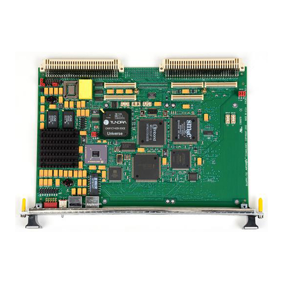
BajaPPC-750: Setup 2.2 BajaPPC-750 Circuit Board The BajaPPC-750 is a 14-layer board. Standard board spacing is 0.800 inches. The dimensions of the BajaPPC-750 board are given in Table 2-1. Table 2-1. Mechanical Specifications Width Depth Height 9.187 in. 6.299 in. -
Page 30: Figure 2-1. Component Map, Top (Board Rev. 23)
BajaPPC-750 Circuit Board C103 C121 C120 C129 C128 U917 C135 C114 C113 C126 C193 C124 R295 C251 RN900 RN901 RN909 RN911 R113 C115 C119 C127 C130 C125 R321 R124 R338 R140 R150 R154 R166 R167 C324 R106 R115 R118 R122... -
Page 31: Figure 2-2. Component Map, Bottom (Board Rev. 23)
BajaPPC-750: Setup R405 R406 R407 R408 C313 C189 R409 R410 R411 R412 R413 R414 R415 R416 R417 R418 R419 C166 C335 C308 C160 R423 R424 R425 R426 R427 R428 R429 R430 R431 R432 R433 C390 R267 R934 R919 R906 R932... -
Page 32: Figure 2-3. Component Map, Top (Board Rev. 22)
BajaPPC-750 Circuit Board C103 C121 C120 C129 C128 U917 C135 C114 C113 C126 C193 C124 R295 C251 RN900 RN901 RN909 RN911 R113 C115 C119 C127 C130 C125 R321 R124 R338 C324 R140 R150 R154 R166 R167 R106 R115 R118 R122... -
Page 33: Figure 2-4. Component Map, Bottom (Board Rev. 22)
BajaPPC-750: Setup R405 R406 R407 C313 R408 C189 R409 R410 R411 R412 R413 R414 R415 R416 R417 R418 R419 C166 C335 C308 C160 R423 R424 R425 R426 R427 R428 R429 R430 R431 C390 R432 R433 R267 R919 R934 R906 R932... -
Page 34: Figure 2-5. Component Map, Top (Board Rev. 21)
BajaPPC-750 Circuit Board C103 C121 C120 C129 C128 C114 C135 R176 C113 C126 C193 C124 R107 R121 C115 C119 R113 C127 C130 C125 R116 R119 R135 R150 R154 R166 R140 R106 R115 R118 R122 R165 R112 R164 R105 R163 R162... -
Page 35: Figure 2-6. Component Map, Bottom (Board Rev. 21)
BajaPPC-750: Setup C162 C374 R211 HDR4 C387 C376 R478 R197 C198 C297 Debug R374 R196 R375 C296 R380 R195 R384 R383 C295 R194 R477 R193 R398 R192 C349 C338 C329 C322 R397 R483 R329 R191 R479 C280 C249 C267 C239... -
Page 36: Figure 2-7. Component Map, Top (Board Rev. 1)
BajaPPC-750 Circuit Board Figure 2-7. Component Map, Top (Board Rev. 1) 0002M621-15... -
Page 37: Figure 2-8. Component Map, Bottom (Board Rev. 1)
2-10 BajaPPC-750: Setup HDR4 Debug 4 Meg Flash 2 Meg Flash 2 Meg Flash 2 Meg Flash 2 Meg Flash Figure 2-8. Component Map, Bottom (Board Rev. 1) May 2002... -
Page 38: Figure 2-9. Jumper And Fuse Locations
BajaPPC-750 Circuit Board 2-11 Figure 2-9. Jumper and Fuse Locations 0002M621-15... -
Page 39: Serial Numbers
2-12 BajaPPC-750: Setup 2.2.2 Serial Numbers Before you install the BajaPPC-750 in a card cage or system, you should record the following information: ❑ The board serial number: _____________________________________ . The board serial number appears on a bar code sticker located on the back of the board. -
Page 40: Reset/Interrupt Switch
8-bit register at FF9E,0000 2.2.5 LED The BajaPPC-750 has a seven-segment LED on the front panel. The control regis- ter for this LED is located in a PLD at FF98,0000 . Each bit of this register con- trols a particular segment of the seven-segment display. -
Page 41: Optional Vmebus Configurations
Register Map 2-1. BajaPPC-750 Board Configuration (P2 Configuration) 2.3 BajaPPC-750 Setup You need the following items to set up and check the operation of the Artesyn BajaPPC-750. ❑ Artesyn BajaPPC-750 microcomputer board ❑ Card cage and power supply ❑... -
Page 42: Providing Power
2.3.1 Providing Power Be sure your power supply is sufficient for the board. Without a PMC module, the BajaPPC-750 requires about 30 watts maximum. With two PMC modules, the requirement is approximately 45 watts maximum. Power supply ripple and noise below 10 MHz should be limited to 50 mV peak-to-peak (a requirement of the VMEbus specification). -
Page 43: Operational Checks
2. Visually inspect the board for components that could have loosened during shipment. Visually inspect the chassis and all cables. 3. Install the BajaPPC-750 in the VMEbus card cage. Be sure the board is seated firmly. 4. Connect a CRT terminal to serial port A via connector P4 or the transition module console port. -
Page 44: Troubleshooting
❑ Be sure the system is not overheating. ❑ Check the power cables and connectors to be certain they are secure. ❑ If you are using the BajaPPC-750 monitor, run the power-up diagnostics and check the results. “Monitor”, Chapter 10 describes the power-up diagnostics. -
Page 45: Technical Support
2.6.2 Service Information If you plan to return the board to Artesyn Communication Products for service, call 1-800-327-1251 and ask for our Test Services Department (or send e-mail to serviceinfo@artesyncp.com) to obtain a Return Merchandise Authorization (RMA) number. -
Page 46: Central Processing Unit
Central Processing Unit This chapter is an overview of the processor logic on the BajaPPC-750. It includes information on the CPU, exception handling, and cache memory. The BajaPPC- ™ 750 utilizes the IBM PPC750 PowerPC microprocessor, running at an internal clock speed of 366 MHz or higher. -
Page 47: Processor Reset
Register Map 3-1. BajaPPC-750 Board Configuration (Reset) 3.2 Processor Initialization Initially, the BajaPPC-750 powers up with specific values stored in the CPU regis- ters. The initial power-up state of the Hardware Implementation Dependent reg- ister (HID0) and the Machine State register (MSR) are given in Table 3-2. -
Page 48: Hardware Implementation Dependent Register
The Hardware Implementation Dependent Register, HID0, contains bits for CPU-specific features. Most of these bits are cleared on initial power-up of the BajaPPC-750. Please refer to the PPC750 RISC Microprocessor User’s Manual for more detailed descriptions of the individual bit fields. The following register map... -
Page 49: Machine State Register
The Machine State Register, MSR, configures the state of the PPC750 CPU. On ini- tial power-up of the BajaPPC-750, most of the MSR bits are cleared. The MSR may be read using the Move to Machine State Register (mtmsr) instruction. The mtmsr, System Call (sc), and Return from Exception (rfi) instructions may be used to modify the MSR. -
Page 50: Table 3-3. Ieee Floating-Point Exception Modes
Instruction and data address translation enables. Recoverable exception enable for system reset and machine check. This feature is enabled on initial power-up. Little-endian mode enable. On the BajaPPC-750, this bit must set to zero so that the processor always runs in big-endian mode. 0002M621-15... -
Page 51: Exception Handling
BajaPPC-750: Central Processing Unit 3.3 Exception Handling Each CPU exception type transfers control to a different address in the vector table. The vector table normally occupies the first 2000 bytes of RAM (with a base address of 0000,0000 ) or ROM (with a base address of FF80,0000 ). -
Page 52: Interrupt Handling
Interrupt Handling 3.4 Interrupt Handling The interrupt controller on the BajaPPC-750 is a programmable logic device (PLD) that handles seven local interrupts and receives external interrupts from the counter/timers and PMC modules. (See Chapters 6 and 9 for additional infor- mation.) The interrupt controller drives the 750_INT* interrupt input on the... -
Page 53: Bus Speed
Register Map 3-5. BajaPPC-750 Board Configuration (Bus Speed) 3.6 Cache Memory The PPC750 processor has separate, on-chip, 32-kilobyte instruction and data caches with eight-way, set-associative translation lookaside buffers (TLBs). The CPU supports the modified/exclusive/invalid (MEI) cache coherency protocol. -
Page 54: Integrated Level 2 Cache
In addition to the on-chip caches, the PPC750 CPU utilizes a 1-megabyte, integrated secondary cache provided by two synchronous random access mem- ory (SRAM) chips. For the BajaPPC-750, the cache operates in Fast L2 mode and integrates data, tag, host interface, and LRU memory with a cache controller. At 122 MHz and above, it performs with zero wait states (2-1-1-1 burst). -
Page 55: Jtag/Cop Interface
Checkstop Output. When asserted, this output signal indicates that the CPU has detected a checkstop condition and has ceased operation. This signal also drives the HALT LED on the BajaPPC-750 circuit board. HRESET* Hard Reset. This input signal is used at power-up to reset the processor. -
Page 56: Debug Header
Debug Header 3-11 3.8 Debug Header In addition to the COP/JTAG interface, the BajaPPC-750 has a debug header at HDR4 on the back of the board to provide easy access to the following signals: Table 3-7. Debug Header Pin Assignments (HDR4) - Page 57 3-12 BajaPPC-750: Central Processing Unit May 2002...
-
Page 58: On-Card Memory Configuration
Configuration The BajaPPC-750 has a 32-pin, plastic-leaded chip carrier (PLCC) socket to sup- port up to 512 kilobytes of EPROM or flash memory. The BajaPPC-750 also incor- porates an 8-bit, 4-megabyte flash device and a 64-bit, 8-megabyte flash bank to provide an additional 12 megabytes of User Flash memory. -
Page 59: Boot Memory Configuration
Configuration Data Register at FEE0,0000 4.2 Boot Memory Configuration The BajaPPC-750 has a 32-pin PLCC socket for either a byte-wide EPROM (up to 512 kilobytes) or a 512-kilobyte flash memory chip. This socketed memory occu- pies physical address space FF90,0000-FF97,FFFF CAUTION. -
Page 60: User Flash
Register Map 4-1. BajaPPC-750 Flash Bank Select In addition to the four megabytes of paged User Flash, the BajaPPC-750 provides another eight megabytes of 64-bit wide flash, beginning at address FF00,0000 This memory must be accessed with 64-bit transfers from the PowerPC. -
Page 61: Sdram Configuration
A programmable logic device (PLD) maintains these configuration values, which are determined by whether or not specific configuration resistors are physically installed on the BajaPPC-750 circuit board. The following table describes the con- figuration bit selections: Table 4-3. Memory Configuration Bit Values... -
Page 62: Table 4-4. Sdram Access Time Required For The Bajappc-750
) have been carefully tuned for optimum memory cycle times for 100-MHz SDRAMs (running at 83MHz in the current configuration) under a variety of conditions. The table below describes the wait states for the BajaPPC-750. Table 4-4. SDRAM Access Time Required for the BajaPPC-750 Cycle... -
Page 63: Real-Time Clock
SRAM array and supporting circuitry. The M48T35 is pin- and function-compatible with standard JEDEC 32K x 8 SRAMs. The real-time clock and NVRAM are mapped in the BajaPPC-750 memory space beginning at FF9C,0000 CAUTION. - Page 64 Real-Time Clock The Real-Time Clock Configuration Registers contain all of the clock/calendar data and calibration information. Under normal operating conditions, the M48T35 operates as a conventional byte-wide static RAM. If the supply voltage drops below the V (min) threshold, the device automatically protects itself by taking all outputs to high impedance and treating all inputs as “don’t care.”...
-
Page 65: Nonvolatile Memory Map
BajaPPC-750: On-Card Memory Configuration 4.6 Nonvolatile Memory Map A portion of ROM is reserved by Artesyn for data storage. The following memory map convention allows various operating systems to store their boot parameters without affecting each other. Table 4-5. Nonvolatile Memory Map... -
Page 66: Pmc/Pci Interface
Interrupts Each PMC expansion site supports the four PCI interrupt lines. Initiator/Master The MPC106 can allow the BajaPPC-750 CPU to act as a PCI bus cycle initiator. Target/Slave The MPC106 can act as a PCI bus target for other initiator devices, such as PMC modules, Ethernet devices, or VMEbus controllers. -
Page 67: Pmc Module Installation
BajaPPC-750: PMC/PCI Interface 5.2 PMC Module Installation The BajaPPC-750 has two PMC expansion sites—J1x and J2x. A single-width PMC module may be installed at each of these sites, or a double-width module may be installed over both sites. Each site includes a cutout in the front panel for I/O. -
Page 68: Pci Bridge Configuration Registers
3. If the BajaPPC-750 is installed in a system, turn off power to the BajaPPC-750 before removing it from the system. 4. Set up the PMC module and install it on the BajaPPC-750 as specified in the module’s hardware manual. -
Page 69: Pci Command Register
MAX_GNT (PCI bus access rate) MPC106 Bus Number Assignment Subordinate Bus Number Target Disconnect Timeout Counter The MPC106 registers are accessed through the BajaPPC-750 Configuration Address and Data registers at FEC0,0000 and FEE0,0000 . To initiate an access, write the value 0x8000,00nn (where nn is the MPC106 address of the register you want to access) to the Configuration Address register at FEC0,0000 . -
Page 70: Pci Status Register
PCI Bridge Configuration Registers Special cycles. Hardwired to zero (ignore SC commands). Bus master. 0=PCI access disable, 1=bus master enable. Memory space access response. 0=disable, 1=enable. I/O space. Hardwired to zero (no response to PCI I/O space accesses). 5.3.2 PCI Status Register The MPC106 PCI Status Register at hex offset 06 records status information for PCI-related events. -
Page 71: Pci Interface
BajaPPC-750: PMC/PCI Interface 5.4 PCI Interface The MPC106 must be initialized to enable the functions on the chip and to set up the PCI bridge. The PCI bridge is used to decode portions of the local address bus and the PCI address bus. Fig. 5-3 illustrates how the PCI bridge works. -
Page 72: Timing
Section 3.4 for details. 5.4.4 Arbitration PCI arbitration for the BajaPPC-750 is handled by the Winbond Systems Labora- tory W83C553 ISA Bridge chip. This is a programmable arbiter that supports eight masters. Upon power-up in the default mode, the arbiter allows all PCI mas- ters equal access to the local bus. -
Page 73: Pci Bus Control Signals
ACK64*, REQ64* These output signals are used to tell a 64-bit PCI device whether to use the 64-bit or the 32-bit data width. Since the BajaPPC-750 is a 32-bit board, these signals are tied off to indicate the 32-bit data width. - Page 74 PMC INTERRUPTS A, B, C, D. These input lines are used by the PMC module to interrupt the baseboard. The interrupts are routed through the interrupt controller to the CPU on BajaPPC-750. IRDY* INITIATOR READY. This sustained three-state signal indicates that the bus master is ready to complete the data phase of the transaction.
-
Page 75: Pmc Connector Pin Assignments
5-10 BajaPPC-750: PMC/PCI Interface 5.6 PMC Connector Pin Assignments Each PMC expansion site has three 64-pin connectors. Pin assignments are shown in Table 5-3 and Table 5-4. Table 5-3. J1x PMC Connector Pin Assignments +12V P2-C1 FRAME* Ground P2-C17 -12V... -
Page 76: Table 5-4. J2X Pmc Connector Pin Assignments
PMC Connector Pin Assignments 5-11 Table 5-4. J2x PMC Connector Pin Assignments +12V P0-E4 FRAME* Ground P0-C13 -12V TRST* P0-D4 Ground No Connection P0-B13 Ground P0-C4 Ground TRDY* P0-A13 INTA* No Connection P0-B4 IRDY* +3.3V P0-E14 INTB* P0-A4 DEVSEL* Ground P0-D14 INTC* Ground... - Page 77 5-12 BajaPPC-750: PMC/PCI Interface May 2002...
-
Page 78: Vmebus Interface
BajaPPC-750. The Universe is optimized to support high-speed processors and allows for numerous bus masters to share the resources on the bus. The VMEbus supports up to 21 boards. Artesyn tests all of its VMEbus boards in a fully-populated backplane. -
Page 79: Universe Configuration Registers
6.2 Universe Configuration Registers The Tundra Universe II CA91C142 provides a single-chip, VMEbus to PCI inter- face for the BajaPPC-750. Its registers are little-endian and occupy 4 kilobytes of internal memory. These registers are logically divided into three groups as fol- lows: PCI configuration space, Universe device-specific, and VMEbus control and status. - Page 80 Universe Configuration Registers Table 6-1. Universe Internal Register Summary — Continued Hex Offset Mnemonic Name LSI0_BD PCI Slave Image 0 Bound Address Register LSI0_TO PCI Slave Image 0 Translation Offset Universe Reserved LSI1_CTL PCI Slave Image 1 Control LSI1_BS PCI Slave Image 1 Base Address Register LSI1_BD PCI Slave Image 1 Bound Address Register LSI1_TO...
- Page 81 BajaPPC-750: VMEbus Interface Table 6-1. Universe Internal Register Summary — Continued Hex Offset Mnemonic Name LSI6_CTL Local Slave Image 6 Control LSI6_BS Local Slave Image 6 Base Address Register LSI6_BD Local Slave Image 6 Bound Address Register LSI6_TO Local Slave Image 6 Translation Offset...
- Page 82 Universe Configuration Registers Table 6-1. Universe Internal Register Summary — Continued Hex Offset Mnemonic Name VINT_MAP2 VME Interrupt Map 2 Register MBOX0 Mailbox 0 MBOX1 Mailbox 1 MBOX2 Mailbox 2 MBOX3 Mailbox 3 SEMA0 Semaphore 0 Register SEMA1 Semaphore 1 Register 360-3FC Universe Reserved MAST_CTL...
- Page 83 BajaPPC-750: VMEbus Interface Table 6-1. Universe Internal Register Summary — Continued Hex Offset Mnemonic Name VCSR_CTL VMEbus CSR Control Register VCSR_TO VMEbus CSR Translation Offset V_AMERR VMEbus AM Code Error Log VAERR VMEbus Address Error Log VSI4_CTL VMEbus Slave Image 4 Control...
-
Page 84: Initialization Values
Universe Configuration Registers 6.2.1 Initialization Values Some of the Universe registers have recommended initialization values, as described in the table below. Please see the Universe User’s Manual for more infor- mation on the available power-up options. Table 6-2. Recommended Initialization Values for Universe Configure Register Hex Default... -
Page 85: Pci Base Address Register
BajaPPC-750: VMEbus Interface 6.2.2 PCI Base Address Register The Universe PCI Configuration Base Address Register, PCI_BS, at hex offset 010 defines the base address of the Universe register space on PCI and has a resolution of 4 kilobytes. In addition, it determines whether the Universe registers are mapped to memory or I/O space. -
Page 86: Register Map 6-2. Universe Pci Configuration Space And Status, Pci_Csr
Universe Configuration Registers D_PE S_ERR R_MA R_TA S_TA DEVSEL DP_D TFBBC Reserved Reserved MF-BBC SERR_EN WAIT PERESP VGAPS MWI_EN Register Map 6-2. Universe PCI Configuration Space and Status, PCI_CSR D_PE Detected parity error (write 1 to clear). Binary 0=no parity error, 1=parity error. S_ERR Signalled SERR# (write 1 to clear). -
Page 87: Master Control Register
6-10 BajaPPC-750: VMEbus Interface VGAPS VGA palette snoop (read only). Binary 0=disabled. MWI_EN Memory write and invalidate enable (read only). Binary 0=disabled. Special cycles (read only). Binary 0=disabled. Master enable. Binary 0=disable, 1=enable. Target memory enable. Binary 0=disable, 1=enable. Target I/O enable. -
Page 88: Miscellaneous Control Register
Universe Configuration Registers 6-11 VMEbus request mode. Binary 0=demand, 1=fair. VREL VMEbus release mode. Binary 0=release when done, 1=release upon request. VOWN VME ownership bit. (VMEbus masters should not set this bit.) Binary 0=release VMEbus, 1=acquire and hold VMEbus. VOWN_ACK VME ownership bit acknowledge (synchronized to PCI clock). -
Page 89: Vmebus Master Image Registers
Since the MPC106 memory controller currently issues a retry upon detecting a memory select error, the maximum slave window size should be limited to the size of the desired memory-mapped region. The slave window can make any portion of the BajaPPC-750 memory map available on the VMEbus. May 2002... -
Page 90: Vmebus Slave Image Registers
Universe Configuration Registers 6-13 The PCI Slave Image 0 Control Register, LSI0_CTL, at hex offset 100 defines the general VMEbus and PCI bus controls. PWEN Reserved Reserved SUPER Reserved Reserved Register Map 6-5. Universe PCI Slave Image 0 Control, LSI0_CTL Enable the image. -
Page 91: Register Map 6-6. Universe Vme Slave Image 0 Control, Vsi0_Ctl
The slave window can make any portion of the BajaPPC-750 memory map available on the VMEbus. The VMEbus Slave Image 0 Control Register, VSI0_CTL, at hex offset F00 defines general VMEbus and PCI bus controls for this image. -
Page 92: Vmebus Master Interface
VMEbus Master Interface 6-15 SUPER Supervisor/user AM code. Binary 00=reserved, 01=non-privileged, 10=supervisor, 11=both. VMEbus address space. Binary 000=A16, 001=A24, 010=A32, 011=reserved, 100=reserved, 101=CR/CSR, 110=user1, 111=user2. LD64EN Enable 64-bit PCI transactions. Binary 0=disabled, 1=enabled. LLRMW Allow VMEbus to lock PCI bus during RMW. For improved performance, disable this feature until it is needed. -
Page 93: Addressing
Also, slave image spaces must not overlap each other, and master image spaces must not overlap each other. By default, the BajaPPC-750 NVRAM configuration parameters (see Chapter 10) map one VMEbus master and two VMEbus slave images as indicated in the table below: Table 6-3. -
Page 94: Data Transfers
Do not perform any byte-, word-, or longword-wide reads/ writes on the VMEbus while a DMA transaction is pending on a BajaPPC-750 that utilizes revision Z1 of the Universe chip. If another VME master attempts a single-beat slave transaction (byte-, word-, or longword-wide read/write) under this condi- tion, the slave transaction following the single-beat slave transaction will occur at a corrupted address. -
Page 95: Slave Mapping Example
• VMEbus errors will be reported via interrupt to the PCI master, rather than a target-abort. If the BajaPPC-750 processor is a PCI master (via the MPC106), VMEbus errors translate to an external interrupt (vector 500 ) instead of the MCP/TEA. - Page 96 VMEbus Slave Interface 6-19 if (noError < 0){ exit(); /*At this point the Universe should be mapped to its base address in PCI MEM space - i.e. it’s now available as a normal memory-mapped PCI device*/ /*Let’s first clean up the SYSFAIL line - it’s asserted after power up until otherwise noted*/ universeIO->VCSR_CLR |= ES((int)UNIV_VCSR_SYSFAIL);...
-
Page 97: Vmebus Interrupts
6-20 BajaPPC-750: VMEbus Interface /*VSI0_TO = Translation offset into local PCI space*/ universeIO->VSI0_TO = ES((int)VME_PCI_MEM_TRANS_OFF & 0xFFFFF000); /*Window attributes*/ universeIO->VSI0_CTL = ES((int)(UNIV_VSIX_CTL_EN UNIV_VSIX_CTL_PGM_DATA UNIV_VSIX_CTL_SUPER_SUPER | UNIV_VSIX_CTL_LD32EN /*local PCI is 32 bits wide*/ UNIV_VSIX_CTL_VAS_A32 UNIV_VSIX_CTL_LAS_PCIMEM)); return; 6.5 VMEbus Interrupts The Universe interrupt channel allows interrupts to be mapped either to the PCI bus or VMEbus interface. -
Page 98: Interrupter
LINTx interrupt mask. Binary 0=masked, 1=enabled. For the BajaPPC-750 application, the Universe is configured to send VME inter- rupts as LINT outputs to the interrupt controller programmable logic device (PLD), which interrupts the CPU via the 750_INT* line (see Section 3.4). -
Page 99: Vmebus System Controller
BajaPPC-750: VMEbus Interface 6.6 VMEbus System Controller When the BajaPPC-750 circuit board is located in slot 1 of the VME system, the Universe acts as VMEbus system controller. In this capacity, the Universe provides a system clock driver, an arbitration module, an IACK Daisy Chain Driver (DCD), and a bus timer. -
Page 100: Register Map 6-9. Universe Vmebus Register Access Image Control, Vrai_Ctl
Mailboxes 6-23 Two interrupt mapping registers, LINT_MAP2 at offset 340 and VINT_MAP2 at offset 344 , define the mailbox interrupt destinations. For example, writing a value of 000 to LINT_MAP2, bits [2:0], maps the corresponding interrupt source for mailbox 0 to LINT[0]; writing a value of 001 to the same location maps the source to LINT[1];... -
Page 101: Location Monitor
6-24 BajaPPC-750: VMEbus Interface 6.10 Location Monitor The Universe location monitor provides a mechanism for broadcasting events across the VME backplane. It is enabled and defined by the Location Monitor Control Register, LM_CTL, at hex offset F64 . The base address is set by the Loca-... -
Page 102: Semaphores
Semaphores 6-25 The interrupt mapping register, LINT_MAP2 at offset 340 defines the location monitor interrupt destinations. For example, writing a value of 000 LINT_MAP2, bits [18:16], maps the corresponding interrupt source for LM0 to LINT[0]; writing a value of 001 to the same location maps the source to LINT[1];... - Page 103 BG0OUT*-BG3OUT* BUS GRANT (0-3) OUT. Totem-pole signals generated by requesters. An output from the BajaPPC-750 (driven by boards not requesting the bus, in response to the bus-grant-in signals), the bus-grant-out signal indi- cates to the next board in the daisy-chain that it may use the bus.
- Page 104 VMEbus. The Universe drives this signal low at power-up. On the BajaPPC-750, SYSFAIL* may be driven by the board, and it is possible to read the state of the VMEbus SYSFAIL* sig- nal.
-
Page 105: Vmebus Connector Pin Assignments
6-28 BajaPPC-750: VMEbus Interface WRITE* WRITE. A three-state signal generated by the master to indicate whether the data transfer cycle is a read or a write. A high level indicates a read operation; a low level indicates a write operation. -
Page 106: Table 6-6. P0 Connector Pin Assignments
VMEbus Connector Pin Assignments 6-29 Table 6-6. P0 Connector Pin Assignments Row F Row E Row D Row C Row B Row A Reserved Reserved Reserved Reserved Reserved Reserved Reserved Reserved Reserved Reserved +3.3V +3.3V +3.3V PMC J24-1 PMC J24-2 PMC J24-3 PMC J24-4 PMC J24-5... -
Page 107: Table 6-7. P1 Connector Pin Assignments (Standard Configuration)
6-30 BajaPPC-750: VMEbus Interface Table 6-7. P1 Connector Pin Assignments (Standard Configuration) Row Z Row A Row B Row C Row D No Connection BBSY* No Connection BCLR* No Connection ACFAIL* No Connection BG0IN* No Connection No Connection BG0OUT* No Connection... -
Page 108: Table 6-8. P1 Connector Pin Assignments (Optional Configuration)
VMEbus Connector Pin Assignments 6-31 Table 6-8. P1 Connector Pin Assignments (Optional Configuration) Row A Row B Row C BBSY* BCLR* ACFAIL* BG0IN* BG0OUT* BG1IN* BG1OUT* BG2IN* BG2OUT* SYSCLK BG3IN* SYSFAIL* BG3OUT* BERR* DS1* BR0* SYSRESET* DS0* BR1* LWORD* WRITE* BR2* BR3* DTACK*... -
Page 109: Table 6-9. P2 Connector Pin Assignments (Standard Configuration)
6-32 BajaPPC-750: VMEbus Interface Table 6-9. P2 Connector Pin Assignments (Standard Configuration) Row Z Row A Row B Row C Row D TXD-B PMC J14-2 PMC J14-1 RTS-B PMC J14-4 PMC J14-3 CTS-B RXD-B PMC J14-6 RETRY* PMC J14-5 DSR-B... -
Page 110: Table 6-10. P2 Connector Pin Assignments (Optional Configuration)
VMEbus Connector Pin Assignments 6-33 Table 6-10. P2 Connector Pin Assignments (Optional Configuration) Row A Row B Row C PMC J14-2 AUI_CI* PMC J14-4 AUI_CI PMC J14-6 No Connection AUI_DO* PMC J14-8 AUI_DO PMC J14-10 AUI_DI* PMC J14-12 AUI_DI PMC J14-14 AUI_PWR PMC J14-16 P_STB*... - Page 111 6-34 BajaPPC-750: VMEbus Interface May 2002...
-
Page 112: Ethernet Interface
Ethernet Interface The BajaPPC-750 provides a local area network (LAN) interface using the Intel (formerly DEC) 21143 PCI/CardBus 10/100-Mb/s Ethernet LAN Controller. The 21143 is a single-chip PCI bus master, supporting direct memory access (DMA) and full-duplex operation on either a 10Mb/s AUI port or 10/100Mb/s Fast Ether- net port with transceiver and clock recovery support from an ICS 1890 PHY device. -
Page 113: Configuration
BajaPPC-750: Ethernet Interface 7.1.1 Configuration The Intel 21143 allows for complete initialization and configuration from soft- ware. Write operations to reserved portions of the configuration registers com- plete normally, discarding any data. Read operations to these areas also complete normally, returning a value of zero. A hardware reset places the default values in the configuration registers, and a software reset (CSR0, bit 0) has no effect. -
Page 114: Ethernet Address
The last two pairs of hex numbers correspond to the following formula: n – 1000, where n is the unique serial number assigned to each board. For exam- ple, if the serial number of a BajaPPC-750 is 2867, the calculated value is 1867 (74B ). -
Page 115: Default Ethernet Boot Device
7.3 Default Ethernet Boot Device The Intel 21143 supports a variety of Ethernet modes. Since the hardware alone cannot determine the Ethernet configuration, the BajaPPC-750 provides a means for software to detect the mode via the jumper installations at JP1. These jumpers indicate the default Ethernet boot device as follows: Table 7-3. -
Page 116: Ethernet Ports
Ethernet Ports 7.5 Ethernet Ports The BajaPPC-750 has a versatile Ethernet interface. It supports full-duplex opera- tion on either a 10/100Mb/s Fast Ethernet port or a 10Mb/s AUI port. The follow- ing sections describe these ports. 7.5.1 Fast Ethernet The Intel 21143 media-independent interface (MII) and ICS 1890 PHY device sup- port 10/100Mb/s communications for the Fast Ethernet port, which is available at the P3 connector on the front panel. -
Page 117: Cabling Considerations
BajaPPC-750: Ethernet Interface 7.6 Cabling Considerations The BajaPPC-750 Ethernet interface complies with the IEEE P802.3u/D3 and ANSI TP-PMD v2.0 UTP CAT 5 standards for Fast Ethernet. Since the 21143 LAN con- troller can operate at up to 100 Mb/s, UTP CAT 5 (unshielded twisted pair, cate- gory 5) cabling is highly recommended. -
Page 118: Serial And Parallel I/O
8.1 PCI to ISA Bridge The PCI to ISA bus interface for the BajaPPC-750 is provided by a Winbond Sys- tems Laboratory W83C553 integrated circuit. The W83C553 ISA bridge features: •... -
Page 119: Basic Operation
The W83C553 is an integrated device that bridges the PCI and ISA busses and performs PCI arbitration. In addition, it has other features (such as common ISA I/O functions) which are unimplemented for the BajaPPC-750. In its basic operation, the W83C553 translates cycles from the PCI bus onto the ISA bus, performing as a standard ISA bus controller with data buffering logic. - Page 120 PCI to ISA Bridge Table 8-2. W83C553 Internal Register Summary — Continued Hex Offset Type Name Default AT System Control AT Bus Control PCI Arbiter Priority Control PCI Arbiter Priority Extension Control PCI Arbiter Priority Enhanced Control PCI Arbiter Control DMA Controller I/O Registers 00;...
-
Page 121: I/O Controller
The SMC FDC37C935 Ultra I/O controller is a versatile single-chip device that provides support for keyboard, mouse, hard disk, floppy disk, parallel port, and serial port input/output. NOTE. Only the parallel port and high-speed serial channels are utilized in the BajaPPC-750 implementation of this chip. May 2002... -
Page 122: Block Addressing
I/O Controller 8.2.1 Block Addressing The CPU accesses the Ultra I/O controller through a series of read/write registers, which have configurable base addresses. All of the I/O registers are 8 bits wide with the exception of a 16-bit IDE data register at port 1F0 .The following table summarizes the I/O port addressing scheme: Table 8-3. - Page 123 BajaPPC-750: Serial and Parallel I/O Table 8-4. Ultra I/O Configuration Registers — Continued Hex Index Access Hard Reset Soft Reset Register Name TEST 3 Logical Device 0 Configuration Registers (FDD) Activate 60, 61 03, F0 03, F0 Primary Base I/O Address...
- Page 124 I/O Controller Table 8-4. Ultra I/O Configuration Registers — Continued Hex Index Access Hard Reset Soft Reset Register Name IR Options Register Logical Device 6 Configuration Registers (RTC) Activate Primary Interrupt Select Real Time Clock Mode Register Serial EEPROM Mode Register Serial EEPROM Pointer Write EEPROM Data bits [6:0] R...
-
Page 125: Serial Ports
BajaPPC-750: Serial and Parallel I/O 8.3 Serial Ports The Ultra I/O controller provides two high-speed Universal Asynchronous Receiver/Transmitter (UART) devices. Each UART channel is programmable for baud rate, start/stop bits, parity, and prioritized interrupts. Please refer to the Ultra I/O Controller User’s Manual for complete information on the serial ports. -
Page 126: Register Map 8-2. Ultra I/O Serial Port Interrupt Identification, Iir
Serial Ports ERDAI Enable received data available interrupt. 1 = enable ETHREI Enable transmitter holding register empty interrupt. 1 = enable ELSI Enable receiver line status interrupt. Error sources are Overrun, Parity, Framing, and Break. 1 = enable EMSI Enable modem status interrupt. This bit is set when MSR bits change state. -
Page 127: Register Map 8-4. Ultra I/O Serial Port Modem Control, Mcr
8-10 BajaPPC-750: Serial and Parallel I/O Even parity select. With PEN enabled, 0 = odd parity and 1 = even parity STICK Stick parity bit. With PEN enabled, 1 = parity bit transmitted and detected by receiver in opposite state from EPS bit BREAK Set break control bit. -
Page 128: Register Map 8-6. Ultra I/O Serial Port Modem Status, Msr
Serial Ports 8-11 Parity error. 1 = parity error detected. This bit is reset when read. Framing error. 1 = framing error detected (no stop bit). This bit is reset when read. Break interrupt. 1 = received data was held at logic “0” for longer than a full word transmission time. -
Page 129: Programmable Baud Rate
8-12 BajaPPC-750: Serial and Parallel I/O 8.3.3 Programmable Baud Rate The Ultra I/O controller has a programmable baud rate generator that works in conjunction with the two 8-bit Divisor Latch registers, DLL and DLM. The baud rate generator can divide the clock input by a number from 1 to 65535, which is stored as a 16-bit binary value in the DLL and DLM registers. -
Page 130: Connectors And Cabling
8.3.4 Connectors and Cabling The Ultra I/O Controller provides two standard EIA-232 serial I/O ports. Serial Port A is available at the BajaPPC-750 front panel P4 connector (standard con- figuration only) and at the VMEbus P2 connector (optional configuration). Table 8-7 lists the pinouts for the front panel connector. A console adapter (Fig. 8- 2) also is available for this connector, providing connectivity with a standard DB25 connector. -
Page 131: Figure 8-2. Console Adapter #308A006-48 For Serial Port A
Figure 8-2. Console Adapter #308A006-48 for Serial Port A Serial Port B is available at header HDR3 (see Table 8-8 for pinouts) on the BajaPPC-750 circuit board and also at the VMEbus P2 connector (see Table 6-10 for pinouts). Fig. 8-3 shows the cable assembly for header HDR3. -
Page 132: Handshaking Jumper
(with strain relief, connector up) AMP P/N 747052-2 Figure 8-3. Cable Assembly #314A002-12 for Serial Port B 8.3.5 Handshaking Jumper A jumper on the BajaPPC-750 circuit board determines whether or not EIA-232 handshaking is enabled as follows: Table 8-9. EIA-232 Handshaking Configuration Jumper Jumper... -
Page 133: Parallel Port Addressing
8-16 BajaPPC-750: Serial and Parallel I/O 8.4.1 Parallel Port Addressing The base address for the BajaPPC-750 parallel port is FE00, 0110 . The CPU can read/write the control and data registers. In Enhanced Parallel Port (EPP) mode, the status register also is read/write. (The EPP registers are available only in EPP mode. -
Page 134: Register Map 8-9. Ultra I/O Parallel Port Control
Parallel Port (Optional) 8-17 Paper End. Read by CPU as bit 5 of Printer Status Register. 0 = paper is loaded, 1 = paper end detected SLCT Printer Selected Status. Read by CPU as bit 4 of Printer Status Register. 0 = not selected, 1 = selected nERR Error. - Page 135 8-18 BajaPPC-750: Serial and Parallel I/O May 2002...
-
Page 136: Counter/Timers
Counter/Timers The interrupt control and counter/timer functions for the BajaPPC-750 are han- dled by a programmable logic device (PLD). Interrupts from the processor, reset facilities, Ethernet, VMEbus, PMC, and ISA subsystems are routed by this PLD. It is addressed by four lines from the boot ROM and has 32 DRAM data lines. -
Page 137: Period Register
BajaPPC-750: Counter/Timers 9.2.1 Period Register The Period Register, CTPR, specifies the period to be used by the counter/timer. The value written indicates the number of 14.31818 MHz clocks between inter- rupts. This register can specify periods from 120 nanoseconds to 4.29 minutes. -
Page 138: Interrupt Acknowledge Register
Counter/Timer Registers The bits (0:7) return the current state of the timer. These status bits are modified by the timer and can change at any time. The interrupt pending, overflow, and count-in-progress status bits are directly controlled by the state of the timer, and are used to determine the state of the timer. -
Page 139: Mode Register
BajaPPC-750: Counter/Timers 9.2.5 Mode Register The timer Mode Register, CTMR, is used to initialize and start the timer. The for- mat of this register is described in the following table. StrStp IntrEn OvFlEn CTMode Enable Register Map 9-2. Counter/Timer Mode, CTMR... -
Page 140: Monitor
Monitor The BajaPPC-750 monitor consists of about 150 C language functions. The moni- tor commands are a subset of these functions that provide easy-to-use tools for configuring the BajaPPC-750 at power-up or reset, as well as for communications, downloads, and other common tasks. This chapter describes the monitor’s fea- tures, basic operation, and configuration sequences. -
Page 141: Figure 10-1. Monitor Start-Up Display
DEC 21143A Test on Port A PASSED Serial Port 1 Test PASSED Serial Port 2 Test PASSED Clearing memory on powerup... Copyright Artesyn Technologies, 1999 Created: Mon Jun 7 11:51:11 1999 ======= Baja750(TM) Debug Monitor ========= Artesyn Technologies. Ver 1.0... -
Page 142: Command-Line History
Monitor Features 10-3 10.1.2 Command-Line History The monitor maintains a history of up to 50 command lines for reuse. Press the <ESC> key from the command line to access the history. k or - Move backward in the command history to access a previous command. -
Page 143: Powerpc Debugger
10-4 BajaPPC-750: Monitor Change text from the cursor to the end of the line. Delete. Use additional commands with d to delete words or groups of words, as shown below. dw or dW Delete a word after the cursor (capital W ignores punctuation). -
Page 144: Basic Operation
10.2 Basic Operation The BajaPPC-750 monitor performs various configuration tasks upon power-up or reset. This section describes the monitor operation as it relates to these specific tasks and the memory initialization. The flowcharts beginning on page 9 illus- trate the power-up/reset sequence (bold texts in flowcharts indicate NVRAM parameters). - Page 145 10-6 BajaPPC-750: Monitor 5. Write a “3” to the LED display. Activiate serial port 1 on the Ultra I/O control- ler. 6. Write a “4” to the LED display. Perform a rotating bit test on the scratch regis- ter of the UART. If an error is detected, the LED display will flash “A”...
- Page 146 Basic Operation 10-7 DRAM parity test flags (Table 10-1) report failures. If an error occurs, the test attempts to determine which byte lanes failed the parity test. Afterwards, the diagnostics continue with parity disabled. 16. Write a “C” to the LED display. Perform a rotating bit test on the first 0x40000 of memory required by the monitor.
-
Page 147: Table 10-1. Power-Up Diagnostic Pass/Fail Flags
10-8 BajaPPC-750: Monitor Table 10-1. Power-up Diagnostic PASS/FAIL Flags Device Value Read on Failure Monitor Test Command Console Serial Port 0xa5000001 serialtest Counter/Timer 0xa5000002 itc_test Real Time Clock 0xa5000004 – 0xa5000008 – Cache 0xa5000010 cachetest NVRAM 0xa5000020 nvramtest Flash 0xa5000040... -
Page 148: Figure 10-2. Monitor Startup Flowchart (1 Of 4)
Basic Operation 10-9 MemParity PowerUpDiags ResetDiags Figure 10-2. Monitor Startup Flowchart (1 of 4) 0002M621-15... -
Page 149: Figure 10-3. Monitor Startup Flowchart (2 Of 4)
10-10 BajaPPC-750: Monitor Figure 10-3. Monitor Startup Flowchart (2 of 4) May 2002... -
Page 150: Figure 10-4. Monitor Startup Flowchart (3 Of 4)
Basic Operation 10-11 ThermProtect L2State InstCache? DataCache? Figure 10-4. Monitor Startup Flowchart (3 of 4) 0002M621-15... -
Page 151: Figure 10-5. Monitor Startup Flowchart (4 Of 4)
10-12 BajaPPC-750: Monitor MemParity ClrMemOnPowerUp ClrMemOnReset RomBase RomBase LoadAddress BankSelect CopyToLoadAdr LoadAddress Rombase Rombase Figure 10-5. Monitor Startup Flowchart (4 of 4) May 2002... -
Page 152: Initializing Memory
NVRAM, test, remote host, arithmetic, and other commands. NOTE. The BajaPPC-750 monitor performs argument checking for com- mands, but not for functions. (Please see Section 10.13 for function reference.) 10.3.1 Command Syntax... -
Page 153: Typographic Conventions
10-14 BajaPPC-750: Monitor octal 1234567:8 binary 101010:2 • The default numeric base for functions is hexadecimal. Some commands use a different default base. • String arguments must start and end with double quotation marks (“). For example, typing the argument “Foo” would result in a string argument with the value Foo, which is passed to the command. -
Page 154: Booteprom
Boot Commands 10-15 bootbus uses the “LoadAddress” field from the nonvolatile memory definitions group ‘BootParams’ (see Table 10-3) as the base address of a shared memory com- munications structure, described below: struct BusComStruct unsigned long MagicLoc; unsigned long CallAddress; The structure consists of two unsigned long locations. The first is used for syn- chronization, and the second is the entry address of the application. -
Page 155: Bootrom
10-16 BajaPPC-750: Monitor In order for the monitor to jump to the start of the program, the first long word of the EPROM image must contain a branch link (bl) instruction of the form 0100,10xx,xxxx,xxxx,xxxx,xxxx,xxxx,xx01 You can avoid jumping to an EPROM, even if a valid one is present, by changing the nonvolatile configuration parameter “BootDev”... -
Page 156: Bootserial
Intel MCS-86 Hexadecimal Format MOT_EXORMAT 1 Motorola Exormax Format (S0-S3,S7-S9 Records) HK_BINARY 2 Artesyn Binary Format The nonvolatile configuration is modified with the NVRAM commands nvdis- play and nvupdate. When the application is called, three parameters are passed to the application from the nonvolatile memory boot configuration section. -
Page 157: Memory Commands
10-18 BajaPPC-750: Monitor 10.5 Memory Commands The memory commands provide facilities for manipulating specific regions of the memory. For some memory commands, the data size is determined by the follow- ing flags: for data in 8-bit bytes for data in 16-bit words for data in 32-bit long words 10.5.1 checksummem... -
Page 158: Copymem
Memory Commands 10-19 10.5.4 copymem copymem source destination bytecount copies bytecount bytes from the source address to the destination address. DEFINITION int CopyMem(unsigned char *Src, unsigned char *Dest, unsigned long ByteCount) 10.5.5 displaymem displaymem startaddr lines displays memory in 16-byte lines starting at address startaddr. -
Page 159: Findmem
10-20 BajaPPC-750: Monitor 10.5.7 findmem findmem -[b,w,l] searchval startaddr endaddr searches memory for a value from address startaddr to address endaddr for memory locations specified by the data searchval. DEFINITION int FindMem(char Flag, unsigned long SearchVal, unsigned long StartAddr, unsigned long EndAddr, unsigned long InvFlag) 10.5.8 findnotmem... -
Page 160: Setmem
Memory Commands 10-21 10.5.11 setmem setmem -[b,w,l] address allows memory locations to be modified starting at address. setmem first displays the value that was read. Then you can type new data for the value or leave the data unchanged by entering an empty line. If you press <cr>... -
Page 161: Writemem
10-22 BajaPPC-750: Monitor 10.5.14 um um -[b,w,l] base_addr top_addr performs a destructive memory test from base_addr to top_addr. This is done by first clearing all memory in the range speci- fied, doing a rotating bit test at each location, and finally filling each data loca- tion with its own address. -
Page 162: Flash Commands
Flash Commands 10-23 10.6 Flash Commands The flash commands affect the User Flash devices on the BajaPPC-750 circuit board. They return zero upon successful completion of the operation, or –1 upon failure. The flash commands protect the monitor code after it is copied into the flash memory. -
Page 163: Flasheraseblk
10-24 BajaPPC-750: Monitor 10.6.4 flasheraseblk flasheraseblk destination erases a 64-kilobyte block of flash memory that con- tains the destination address. DEFINITION int FlashEraseBlk(unsigned char *FlashAddr) 10.6.5 wideflashblkwr wideflashblkwr source destination bytecount writes bytecount from the source address to the destination address (64-bit wide flash memory). All accesses must be 64-bits wide, so bytecount must be a multiple of 8 bytes. -
Page 164: Rewritemonitor
Artesyn-defined and monitor-defined nonvola- tile sections. The nonvolatile memory configuration information is used to com- pletely configure the BajaPPC-750 at reset. The utility command configboard can also be used to reconfigure the board after modifications to the nonvolatile memory. -
Page 165: Table 10-3. Nvram Configuration Groups
10-26 BajaPPC-750: Monitor To quit the display, press <ESC> or Q. To save the changes, type the command nvupdate. To quit without saving the changes, type the command nvopen. Table 10-3 shows all the groups and fields you can edit with the nvdisplay com- mand. - Page 166 NVRAM Commands 10-27 Table 10-3. NVRAM Configuration Groups — Continued Artesyn Group Fields Purpose Optional Values Default ExtMastOffset Set offset for extended (memory range) space master access (address = base + offset) ExtEnabled Enable extended slave map False (True, False)
- Page 167 10-28 BajaPPC-750: Monitor Table 10-3. NVRAM Configuration Groups — Continued Artesyn Group Fields Purpose Optional Values Default Cache InstrCache Turn instruction cache on or (On, Off) DataCache Turn data cache on or off (On, Off) CacheMode Select the cache mode...
- Page 168 (0, 1, 2, 3, 4, 5, 6, 7) taining the application (BootFlash only) HardwareConfig, Manufacturing, Service Reserved for use by Artesyn Communicaton Products manufacturing. EXAMPLE 1. At the monitor prompt, type: nvdisplay 2. Press <cr> until the group you want to modify is displayed. An example for the group “Console”...
-
Page 169: Nvinit
“revlev” ecolev writes is used to initialize the nonvolatile memory to the default state defined by the monitor. First nvinit clears the memory and then writes the Artesyn and monitor data back to memory. It also saves the changes in NVRAM. -
Page 170: Nvupdate
10.7.6 Default Boot Device Configuration Example The default boot device is defined in the nonvolatile memory group ‘Boot- Params,’ in the field “BootDev.” When the BajaPPC-750 is reset or powered up, the monitor checks this field and attempts to boot from the specified device. - Page 171 10-32 BajaPPC-750: Monitor 1. At the monitor prompt, type: nvdisplay 2. Press <cr> until the ‘BootParams’ group is displayed. Group ‘BootParams’ BootDev Bus (None,Serial,ROM,Bus,EPROM,Stos) LoadAddress 0x40000 ROMBase 0xfff30000 ROMSize 0x40000 DevType DevNumber ClrMemOnBoot False(False, True) [SP, CR to continue] or [E, e to Edit] 3.
-
Page 172: Download Port Configuration Example
NVRAM Commands 10-33 3. Press E to edit the group. 4. Press <cr> until the “BootDev” field is displayed. 5. Type the new value “Serial.” 6. Press <cr> until the “DevType” field is displayed. 7. Type the new value for “DevType”; for example, 2 selects downloads in Arte- syn binary format. -
Page 173: Test Commands
10-34 BajaPPC-750: Monitor 10.8 Test Commands The following on-card functional tests are available to be run any time you desire. The nonvolatile configuration memory can be used to enable or disable the exe- cution of these tests on power-up and reset (see the nvdisplay monitor com- mand’s Misc group in Table 10-3). -
Page 174: Serialtest
Test Commands 10-35 • Verifies that Ethernet controller interrupts can be generated, that the CPU responds to the interrupts, and that the interrupt condition can be cleared. • Assures that an Ethernet controller access to a non-responding local bus space results in an ABORT interrupt and that writing to the ABORT-clear address clears the interrupt. -
Page 175: Remote Host Commands
10-36 BajaPPC-750: Monitor one addresses, rotating-zero addresses, and alternating one and zero addresses. The L2 synchronous RAM parity is disabled during the test, and the test restores the L2 cache to the original state when it is finished. DEFINITION int cachetest(void) 10.9 Remote Host Commands... -
Page 176: Download
Remote Host Commands 10-37 10.9.2 download download -[b,h,m] address provides a serial download from a host computer to the board. download uses binary, hex-Intel, or Motorola S-record format, as specified by the following flags: binary (address not used) hex-Intel (load address in memory = address + record address) Motorola S-record (load address in memory = address + record address) If no flag is specified, the default format is hex-Intel. - Page 177 10-38 BajaPPC-750: Monitor segment (ssss) + offset (oooo) = address (aaaaa) For addresses with fewer than 16 bits, the segment portion of the address is unnecessary. The hex-Intel checksum is a two’s complement checksum of all data in the record except for the initial colon (:). In other words, if you add all the data bytes in the record, including the checksum itself, the lower eight bits of the result will be zero if the record was received correctly.
- Page 178 Remote Host Commands 10-39 is the checksum. EXAMPLE :0400100050D55ADF8E In this example, there are four data bytes in the record. They are loaded to address 10 ; if any segment value was previously specified, it is added to the address. 50 is loaded to address 10 , D5 to address 11...
-
Page 179: Motorola S-Record Download Format
10-40 BajaPPC-750: Monitor loads byte 20 to address 00 loads byte 82 to address 01 loads byte E4 to address 02 loads byte 46 to address 03 loads byte A8 to address 04 loads byte 0A to address 05 loads byte 6C... - Page 180 Remote Host Commands 10-41 is the count of data and checksum bytes. d1...dn are the data bytes. is the checksum. S0 records are optional, and can contain any user-defined data. EXAMPLE S008763330627567736D In this example, the length of the field is 8, and the data characters are the ASCII representation of “v30bugs.”...
- Page 181 10-42 BajaPPC-750: Monitor EXAMPLE S5030343B6 In this example, the number of bytes is 3, the checksum is B6 , and the count of the S1-records, S2-records, and S3-records in the file is 343 Termination and Start Address Records (S7, S8, S9)
-
Page 182: Arithmetic Commands
Arithmetic Commands 10-43 byte 4E to address 08 byte FA to address 09 byte FF to address 0A byte FE to address 0B S5030001FB indicates that only one S1-record, S2-record, or S3-record was sent. S9030008F4 indicates that the start address is 00000008 10.10 Arithmetic Commands The commands in this group allow for basic arithmetic functions to be performed at the command line. -
Page 183: Mul
10-44 BajaPPC-750: Monitor 10.10.3 mul mul number1 number2 multiplies two integers in hexadecimal, binary, octal, or decimal (default) from the monitor. The default numeric base is decimal. Specify hex by typing “:16” at the end of the value, octal by typing “:8” or binary by typing “:2.” The result of the operation is displayed in hex, decimal, octal, and binary. -
Page 184: Config_Pci
Other Commands 10-45 configboard can be used to reconfigure the board’s various interfaces after modification of the nonvolatile memory configuration (using nvdisplay or nvset). This command accepts no parameters. DEFINITION void ConfigBoard() 10.11.2 config_PCI config_PCI determines if any PMC modules or PCI devices are present and, if so, uses software polling to determine their type. -
Page 185: Command Errors And Screen Messages
Warning NV memory is invalid - Consult the introduction to this chapter for information using defaults. about reset conditions. 1. Artesyn Communications Products, 1-800-327-1251. Customer Services email support@artesyncp.com, Test Services email serviceinfo@artesyncp.com. May 2002... -
Page 186: Monitor Function Reference
Monitor Function Reference 10-47 10.13 Monitor Function Reference The BajaPPC-750 monitor functions fall into two groups: BajaPPC-750-specific and standard Artesyn monitor functions. For convenience, related functions are combined in groups under a single name. If you can not find a particular func- tion, please refer to the index for the appropriate page number. -
Page 187: Hardware Implementation Dependent Register
10-48 BajaPPC-750: Monitor 10.14.2 Hardware Implementation Dependent Register SYNOPSIS unsigned long getHID0(void) void setHID0(unsigned long 32-bit) void clrHID0(unsigned long 32-bit) DESCRIPTION GetHID0 returns the value of the CPU’s Hardware Implementation Depen- dent register (HID0). Functions SetHID0 and ClrHID0 set and clear the bits in HID0. -
Page 188: Read/Write Configuration
Address is not long-word aligned. NOTE. The MPC106 supports 8-, 16-, and 32-bit reads in the ROM, so readw_bus8 is not necessary. However, it is included for compatibil- ity with other Artesyn products. 10.14.5 Display Processor Temperature SYNOPSIS void DisplayTemp(void) -
Page 189: Standard Artesyn Functions
10-50 BajaPPC-750: Monitor 10.15 Standard Artesyn Functions This section describes functions which are part of the standard Artesyn monitor implementation. 10.15.1 Conversions SYNOPSIS unsigned long atoh(char *p) unsigned long atod(char *p) unsigned long atoo(char *p) unsigned long atob(char *p) unsigned long atoX(char *p, int Base) -
Page 190: Booting
Ethernet, and Stos. ARGUMENTS The flag PowerUp indicates if this function is being called for the first time. If so, memory must be cleared. The BajaPPC-750 clears memory on reset, so PowerUp is always true. SEE ALSO StartMon.c, NvMonDefs.h, NVTable.c, “Boot Commands”, Section 10.4. -
Page 191: Mmu Control
10-52 BajaPPC-750: Monitor void L2_off(void) DESCRIPTION As the names indicate, these functions enable, disable, invalidate, and flush the instruction and data caches. The disable_dcache function calls flush_dcache before disabling the data cache. L2_off should not be called until disable_dcache and flush_L2 have been executed. -
Page 192: Exceptions
Standard Artesyn Functions 10-53 Both serial ports can be configured to use 5 to 8 data bits, 1 or 2 stop bits, the handshake control lines, and odd, even, or no parity. 10.15.6 Exceptions SYNOPSIS vectinit(HANDLER default_handler HANDLERPARAM default_param, unsigned long vectmask) -
Page 193: Serial I/O
10-54 BajaPPC-750: Monitor The function disconnecthandler modifies the interrupt table entry associ- ated with Vector to use the unexpected interrupt handler. It also de-allocates the memory used for the interrupt wrapper allocated by connecthandler. Because both connecthandler and disconnecthandler use the Malloc and Free facilities, it is necessary for memory management to be initialized. -
Page 194: Initialize Board
Standard Artesyn Functions 10-55 The tx_empty and tx_empty_d functions determine whether the transmit- ter is available for sending a character on the console or download port, respectively. If the transmitter is available, they return TRUE; otherwise, they return FALSE. 10.15.8 Initialize Board... -
Page 195: Initialize Ethernet Address
10-56 BajaPPC-750: Monitor struct Fifo { unsigned char *Top; unsigned char *Bottom; int Length; unsigned char *Front; unsigned char *Rear; int Count; } Fifo; The function InitFifo initializes the FIFO control structure specified by FPtr to use the unsigned character buffer starting at StartAddr that is of size Length. -
Page 196: Interrupt Error
Standard Artesyn Functions 10-57 10.15.12 Interrupt Error SYNOPSIS void IntrErr(unsigned char Vector) DESCRIPTION When an unexpected interrupt is received, it is necessary to remove the error condition before returning to the monitor. This function is called from the low-level interrupt service routine, which parses the interrupt record for the address and the vector associated with the interrupt. -
Page 197: Memory Management
10-58 BajaPPC-750: Monitor 10.15.14 Memory Management SYNOPSIS char *Malloc(unsigned long NumBytes) char *Calloc(unsigned long NumElements, unsigned long Size) void Free(unsigned long *MemLoc) void CFree(unsigned long *Block) char *ReAlloc(char *Block, unsigned long NumBytes) void MemReset(void) void MemAdd(unsigned long MemAddr, unsigned long MemSize) -
Page 198: Miscellaneous
Standard Artesyn Functions 10-59 The function MemReset sets the free memory pool to the empty state. This function must be called once for every reset operation and before the mem- ory management facilities can be used. It is also necessary to call this func- tion before every call to MemAdd. -
Page 199: Support Functions
The NvHkOffset and NvMonOffset functions describe where in the nonvol- atile memory device the Artesyn- and monitor-defined data sections begin. In general, the Artesyn-defined data section and the monitor data section reside in the user-writeable section of the nonvolatile memory device. The returned value is the offset in bytes from the beginning of the device in which the sec- tion is loaded. -
Page 200: Table 10-7. Nvop Commands
Standard Artesyn Functions 10-61 } NVEx; NVField ExFields[] = { { “XPos”, (char *) &NVEx.XPos, sizeof(NVEx.XPos), NV_TYPE_DECIMAL, 0, 100, NULL}, { “YPos”, (char *) &NVEx.YPos, sizeof(NVEx.YPos), NV_TYPE_DECIMAL, 0, 200, NULL}, { “Depth” (char *) &NVEx.Mag, sizeof(NVEx.Mag), NV_TYPE_DECIMAL, 0, 4, NULL} NVGroup ExGroups[] = { { “Window”, sizeof(ExFields)/sizeof(NVField), ExFields }... -
Page 201: Seed
10-62 BajaPPC-750: Monitor NVOp(NV_OP_CLEAR, &NVEx, sizeof(NVEx), 0); NVOp(NV_OP_SAVE , &NVEx, sizeof(NVEx), 0); NVOp(NV_OP_OPEN , &NvEx, sizeof(NVEx), 0); NVOp(NV_OP_FIX, &NVEx, sizeof(NVEx), 0); NVOp(NV_OP_SAVE , &NVEx, sizeof(NVEx), 0); The clear, save, and open operations cause the nonvolatile device to be cleared and filled with the NVEx data structure; then the data structure is filled from nonvolatile memory. -
Page 202: Serial Support
Standard Artesyn Functions 10-63 10.15.19 Serial Support SYNOPSIS unsigned char getchar (void) void putchar(char c) int KBHit(void) int TxMT(void) void ChBaud(int Baud) DESCRIPTION The serial support functions defined here provide the ability to read, write, and poll the monitor’s console device, which provides the user interface. The serial port is configured at reset according to the nonvolatile memory config- uration. -
Page 203: Unexpected Interrupt Handler
10-64 BajaPPC-750: Monitor 10.15.20 Unexpected Interrupt Handler SYNOPSIS SetUnExpIntFunct(unsigned long Funct) DESCRIPTION If desired, a program can call the SetUnExpIntFunct function to attach its own interrupt handler to all unexpected interrupts. This function attaches the handler specified by Funct. The new interrupt handler must determine the source of the unexpected interrupt and remove it. -
Page 204: Test Suite
Standard Artesyn Functions 10-65 The function StrLen determines the length of the null terminated string Str and returns the length. If the length exceeds the monitor defined limit MAXLN, the function returns MAXLN. The function StrCat concatenates the string SrcStr onto the end of the string DestStr. -
Page 205: Timer
10-66 BajaPPC-750: Monitor The function LongAddrTest performs a long-oriented test of the specified memory region. Each location is tested by writing the location address through the entire memory region and verifying each location. The function RotTest performs a long word-oriented test of the specified memory region. - Page 206 Standard Artesyn Functions 10-67 DESCRIPTION This function serves as a System V UNIX®-compatible printf() without float- ing point. It implements all features of %d, %o, %u, %x, %X, %c, and %s. An additional control statement has been added to allow printing of binary val- ues (%b).
- Page 207 10-68 BajaPPC-750: Monitor May 2002...
- Page 208 10-14 air flow requirements 2-15 checksum, S-records 10-40 ambiguous command, monitor error 10-46 command reference 10-13 arbitration, PCI 5-7 command-line Artesyn identifier, Ethernet 7-3 editor 10-3 AUI 7-5 history 10-3 autoboot 10-8 interface 10-2 cancellation 10-46...
- Page 209 9-4 of memory from the monitor 10-13 Fast Ethernet of nonvolatile memory, caution 10-30 address 7-3, 10-45 installation AUI 7-5 BajaPPCM 2-14, 2-16 cabling considerations 7-6 PMC module 5-3 features 7-1 INTA* 5-9 port 7-5 INTB* 5-9 Index-2 BajaPPC-750: Index...
- Page 210 INTC* 5-9 compare addresses 10-18 INTD* 5-9 controller 4-1 interrupt copy 10-19 controller PLD 9-1 destructive test 10-22 request, VMEbus 6-27 display 10-19 switch 2-13 fill with specified value 10-19 vectors for CPU 3-7 flash block write 10-23 interrupts flash byte write 10-23 PMC 5-7, 5-9 flash clear status 10-23 VMEbus 6-1...
- Page 211 L2_off 10-52 atod 10-50 L2_on 10-51 atoh 10-50 LongAddrTest 10-65 atoo 10-50 Malloc 10-58 atoX 10-50 maskints 10-56 baud_c 10-52 MemAdd 10-58 baud_d 10-52 MemBase 10-59 BitToHex 10-50 MemReset 10-58 BootUp 10-51 MemStats 10-58 ByteAddrTest 10-65 MemTop 10-59 Index-4 BajaPPC-750: Index...
- Page 212 mmu_data_disable 10-52 Misc 10-28, 10-34 mmu_data_enable 10-52 Network 10-28 mmu_inst_disable 10-52 Service 10-29 mmu_inst_enable 10-52 VMEbus 10-26 NvHkOffset 10-59 MPC106 4-1 NvMonAddr 10-59 NvMonOffset 10-59 NvMonSize 10-59 NVOp 10-60 non-burst cycles 4-5 PingPongAddrTest 10-65 nonvolatile memory Probe 10-53 checking 10-30 put_c 10-54 commands 10-25 put_d 10-54...
- Page 213 10-5 bus clear 6-26 switch 2-13 bus error 6-26 return merchandise authorization (RMA) 2-18 bus grant 6-26 returning the board to Artesyn 2-18 bus request 6-26 data bus 6-26 data strobe 6-26 data transfer acknowledge 6-26 interrupt acknowledge 6-27...
- Page 214 single-width PMC module 5-2 slave Ultra 8-4 interface, VMEbus 6-17 configuration 8-5 specifications Universe environmental 2-15 control registers 6-2 mechanical 2-2 initialization values 6-7 S-records 10-36, 10-37, 10-40 interrupt channel 6-20 file example 10-42 location monitor 6-24 standard address, VME 6-25 mailboxes 6-22 standby power supply 6-28 master control register 6-10...
- Page 215 SECURE ASSET SOLUTIONS Artisan Scientific Corporation / Artisan Technology Group is not an authorized distributor of Artesyn Embedded Technologies, Inc. or Artesyn products. Artesyn Embedded Technologies® is a trademark of Artesyn Embedded Technologies, Inc. and is used for identification purposes only.
Need help?
Do you have a question about the BajaPPC-750 and is the answer not in the manual?
Questions and answers