Sign In
Upload
Manuals
Brands
Artesyn Manuals
Motherboard
MITX-CORE-820
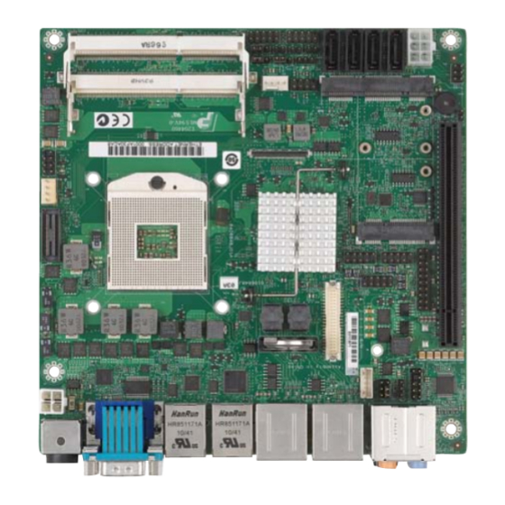
Artesyn MITX-CORE-820 Motherboard Manuals
Manuals and User Guides for Artesyn MITX-CORE-820 Motherboard. We have
1
Artesyn MITX-CORE-820 Motherboard manual available for free PDF download: Installation And Use Manual
Artesyn MITX-CORE-820 Installation And Use Manual (133 pages)
Brand:
Artesyn
| Category:
Motherboard
| Size: 9 MB
Table of Contents
Table of Contents
4
About this Manual
16
Figure
22
Safety Notes
24
Sicherheitshinweise
28
1 Introduction
32
Overview
32
Features
32
Table 1-1 MITX-CORE-820 Features Summary
32
Standard Compliances
34
Table 1-2 Board Standard Compliances
34
Figure 1-1 Declaration of Conformity
36
Mechanical Specifications
37
Figure 1-2 MITX-CORE-820 Mechanical Data (Top View)
37
Board Identification
38
Figure 1-3 MITX-CORE-820 Mechanical Data (Side View)
38
Figure 1-4 MITX-CORE-820 Serial Number Location
38
Ordering Information
39
Table 1-3 Ordering Information
39
2 Hardware Preparation and Installation
40
Environmental and Power Requirements
40
Environmental Requirements
40
Table 2-1 Environmental Requirements
40
Power Requirements
41
Power Dissipation
41
Table 2-2 Power Dissipation of Critical Components
41
Unpacking and Inspecting the Board
42
Preparing the Installation Environment
43
Memory Module Installation
45
Processor Cooler Installation
46
3 Controls, Leds and Connectors
48
Board Layout
48
Figure 3-1 MITX-CORE-820 Module Components
48
Figure 3-2 MITX-CORE-820 Module Components - Continued
49
Connector Definitions
50
Table 3-1 MITX-CORE-820 Connectors
50
LED Controls
51
Table 3-2 LED Control Indicator
51
Rear I/O Connectors
52
Figure 3-3 Rear I/O Connectors
52
4 Functional Description
54
Block Diagram
54
Processor
55
Motherboard Clock Diagram
55
Figure 4-2 Platform Clocks Distribution
55
Chipset
56
System Memory
56
Video
57
Lvds
57
Table 4-2 LVDS Connector (P6)
57
Vga
58
Table 4-3 LVDS Panel VDD Selector (P29)
58
Table 4-4 LVDS Inverter Connector (P8)
58
Figure 4-3 LVDS Inverter Connector (P8)
58
Display Port
59
Embedded Display Port (Edp)
59
Table 4-5 Edp Connector (J15)
59
PCI Express
60
LAN on Motherboard
60
Wifi/Wimax
62
Storage
62
Table 4-8 SATA HDD Power Connector Pinout (P17)
62
Figure 4-4 SATA HDD Power Connector (P17)
62
Usb 2.0
63
Table 4-6 Table
63
Table 4-9 USB Internal Header (P24, P25, P26) Pinout
63
Figure 4-5 USB Internal Header (P24, P25, P26)
63
Power Supplies
64
Figure 4-6 DC-IN Jack Front View
64
Table 4-10 DC-IN Jack Pin Definitions
64
Table 4-11 ATX Power Supply Connector (J12)
64
Figure 4-7 ATX Power Supply Connector Top View
65
Power Consumption
65
Power Management
65
Power Sequencing Requirements
65
Table 4-12 Board MAX Power Consumption Estimation
65
Power Measurement
66
Embedded Controller
66
Voltage Monitor
66
Serial Port
66
Table 4-13 Serial Port Connectors (J5)
66
Fan Header
67
Ps/2
67
Table 4-14 CPU and System Fan Headers (P2 and P23) Description
67
Table 4-15 PS/2 Header (P5) Description
67
Table 4-24 Table
67
Figure 4-8 CPU and System Fan Headers (P2 and P23)
67
Debug Header
68
Charge Board Interface
68
Table 4-16 EC Debug Header (P14) Description
68
Table 4-17 Charge Board Interface (P22)
68
PS/2 Header (P5)
68
SMBUS Architecture
69
Figure 4-10 SMBUS Architecture
69
Audio
70
Table 4-18 Audio Jack Board Side Pin Definitions (J11)
70
Table 4-19 Front Panel Audio Header (P9) Description
71
Figure 4-11 Rear Panel Audio Jack
71
Figure 4-12 Front Panel Audio Header (P9)
71
Watchdog Timer
72
RTC Circuit
72
Boot Block
72
Table 4-20 S/PDIF out Header (P30)
72
Table 4-21 Clear CMOS Header (P4)
72
SPI Flash
73
Front Panel Header
73
Table 4-22 Front Panel Header (P1) Definition
73
Figure 4-13 Front Panel Header (P1)
73
Tpm/Port 80 Interface
74
Table 4-23 Tpm/Port80 Header (P3) Definition
74
Figure 4-14 Tpm/Port80 Header (P3)
74
On Board LED Interface
75
Case Open Header
75
Table 4-26 Case Open Header (P27)
75
Internal Graphics Disable
76
User GPIO Header
76
Debug Support
76
Table 4-27 Internal Graphics Disable Header (P33)
76
Table 4-28 User GPIO Header (P28)
76
Wake Events
77
Manageability
77
5 Bios
78
Power up Self Test (POST)
78
Boot Process
78
Initiating Setup
78
Setup Utility
79
Main Menu
81
Table 5-3 Main Menu Field Description
81
Boot Features
82
System Information
82
Table 5-4 System Information Field Description
82
Table 5-5 Boot Features Field Description
82
Advanced Menu
83
Table 5-6 Advanced Menu Field Description
83
Boot Configuration
84
Table 5-7 Boot Configuration Field Description
84
Processor Configuration
85
Processor Power Management
85
Table 5-8 Processor Configuration Field Description
85
Table 5-9 Processor Power Management Field Description
85
HDD Configuration
86
Peripheral Configuration
86
Table 5-10 Peripheral Configuration Field Description
86
Table 5-11 HDD Configuration Field Description
86
Memory Configuration
87
System Agent (SA) Configuration
87
Table 5-12 Software Feature Mask Configuration Field Description
87
Table 5-13 Memory Configuration Field Description
87
Table 5-14 SA Configuration Field Description
87
Table 5-15 Intel(R) VT for Directed I/O (VT-D) Field Description
88
Table 5-16 Graphics Configuration
88
South Bridge Configuration
89
Table 5-18 South Bridge Configuration Field Description
89
Table 5-19 SB PCI Express Configuration Field Description
90
Table 5-20 PCI Express Port 3//7/8 Configuration Field Description
90
Table 5-21 SB USB Configuration Field Description
90
AMT Configuration
91
Network Configuration
91
Table 5-22 SB Azalia Configuration Field Description
91
Table 5-23 Network Configuration Field Description
91
Table 5-24 AMT Configuration Field Description
91
ME Configuration
92
Table 5-25 ME Configuration Field Description
92
Security Menu
93
Trusted Platform Module (TPM) Configuration
93
Table 5-26 TPM Configuration Field Description
93
Boot Menu
94
Exit Menu
95
Table 5-27 Exit Menu Field Description
95
Miscellaneous
96
Supported os List
96
Driver Control Table
96
Table 5-28 Driver Control Table
96
ACPI Wake up Support Matrix
97
Default Boot Sequence
97
BIOS Status Codes
97
Status Code Ranges
97
Table 5-29 ACPI Wake up Support Matrix
97
Standard Status Codes
98
Table 5-31 Component Status Codes
98
Table 5-32 Progress Status Codes
99
Table 5-33 Architectural Status Codes
99
Accessing the MEBX Setup Menu
100
BIOS Update
100
6 Firmware
102
Embedded Controller Overview
102
Figure 6-1 Npce791X System Block Diagram
102
System BIOS Porting
103
Host Configuration Address
103
Index-Data Register Pair
103
Blanked Logical Device Register Structure
103
Figure 6-2 Structure of Standard Configuration Register
105
Standard Logical Device Configuration Register
106
Table 6-2 Standard Configuration Register Map
106
KBC Address to Host Processor
107
EC I/O Port
107
EC Status Register
107
Table 6-3 Mapping of Host Interface Registers to the Host Processor
107
Table 6-4 EC Status I/O Port Register
107
EC Command Register
108
Table 6-5 EC Command Register
108
EC Command Program Sequence
109
EC Space Definition
109
Table 6-6 EC Command Program Sequence
109
Table 6-7 EC Space Definition
109
Event List
113
OS Driver Support
114
EC Firmware Porting
114
Power Sequence Control
114
Peci
117
Thermal & Fan Speed Control
119
Thermal Trip
119
Thermal Throttling
119
Battery Information - Charging & Discharging Control
119
Voltage Monitor
120
Wake up Requirement
121
Leds Control
121
PS2 Interface & Device Configuration
122
Input Events Detection through GPIO
122
EC Firmware Flash
123
Flash with SF100
123
Flash with ECDT
123
Flash with Utility
123
Crisis Recovery
123
EC Debug Interface
123
Serial Port
123
JTAG Interface
124
Replacing the Battery
126
Overview
126
Figure A-1 Battery Location
126
Procedure Description
127
Related Documentation
130
Artesyn Embedded Technologies - Embedded Computing Documentation
130
Table B-1 Artesyn Embedded Technologies - Embedded Computing Publications
130
Advertisement
Advertisement
Related Products
Artesyn MVME4100
Artesyn MVME55006E
Artesyn MVME6100
Artesyn MVME8100
Artesyn MVME2500 Series
Artesyn MVME2500-0171
Artesyn MVME2500-0173
Artesyn MVME2500-02100202E
Artesyn MVME2500-02100202S
Artesyn MVME2500-02120201E
Artesyn Categories
Motherboard
Server
Single board computers
PCI Card
Computer Hardware
More Artesyn Manuals
Login
Sign In
OR
Sign in with Facebook
Sign in with Google
Upload manual
Upload from disk
Upload from URL