
Summary of Contents for Japa 485
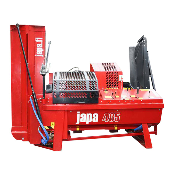
- Page 1 ENGLISH User manual 6.0t 8.0t TR – Tractor drive TRE – Electricity and tractor drive...
-
Page 2: Table Of Contents
TABLE OF CONTENTS Introduction ..........................2 Customer registration ...................... 2 Declaration of conformity ....................3 Purpose of use ......................... 4 Instruction and warning labels on the machine ............... 4 The machine’s type plate ....................5 Machine models ....................... 6 Safety instructions......................7 Noise level and vibration .................... - Page 3 5.4.2 Adjustments of the splitting device ................29 5.4.3 Adjustment of the speeding valve ................. 30 Adjusting the conveyor’s relief valve ................31 5.4.4 5.4.5 Adjusting the switching of splitting power ..............31 Annual maintenance (1,000 hrs) ..................31 5.5.1 Extended maintenance interval ..................
-
Page 4: Introduction
We at JAPA are confident that you will be satisfied with your new firewood processor. It meets all the safety requirements imposed by the European Union and carries the relevant CE label. -
Page 5: Declaration Of Conformity
FI-23800 Laitila, Finland Tel. +358 2857 1200 Fax +358 2857 1201 Web: www.japa.fi Person responsible for the technical file: Ville Kairus The declaration applies to the following machines: JAPA 485 TR 24 t Tractor drive JAPA 485 TRE 24 t Tractor/electrical drive The following directives have been observed in the construction of each machine: Machinery Safety Directive 2006/42/EC brought into effect through Government Decree 400/2008. -
Page 6: Purpose Of Use
20 and 66 cm. The log length limiter is hydraulic. The machine can be equipped with a knife that splits the logs into six, eight or twelve pieces. We place great emphasis on the reliability of our products; the Japa 485... -
Page 7: The Machine's Type Plate
Machine type Production year and date Weight of the machine Voltage (TRE models) Maximum rotation speed of power take-off Maximum pressure of hydraulics Diameter of the cutting blade/blade opening diameter Name and address of manufacturer Terä, Blade Translation 485 1.0-2014... -
Page 8: Machine Models
User manual 1.6 Machine models JAPA 485 TR 24 t Tractor drive JAPA 485 TRE 24 t Tractor/electrical drive Features: Hydraulic 2.5 m input conveyor with series connection Input conveyor reverse capability Hydraulic log length measuring device Additional hydraulics for the hydraulic timber deck, for example Hydraulic 22”... -
Page 9: Safety Instructions
Ensure that the PTO shaft is undamaged and attach the shaft guard chain to the machine. Avoid unnecessary lifting by using a suitable log rack. Do not lift logs directly onto the input table with a loader. DO NOT LEAVE A RUNNING MACHINE UNSUPERVISED! Translation 485 1.0-2014... -
Page 10: Noise Level And Vibration
User manual 1.8 Noise level and vibration The JAPA 485 firewood processor’s sound power level, as specified in standard EN ISO 3744:2010, during a work cycle is 109 dB, while the maximum sound pressure at the operator’s position during a work cycle is 95 dB. -
Page 11: Guarantee Terms
This guarantee certificate indicates our responsibilities and obligations in full and it excludes all other responsibilities. Translation 485 1.0-2014... -
Page 12: Installation Of The Machine
2.2 Main components of the machine Output conveyor Blade guard Knife replacement winch Wood gripper Splitting area guard Control panel Front panel Input opening guard Log length measurement device Input conveyor Translation 485 1.0-2014... -
Page 13: Lifting And Transporting The Machine
User manual 2.3 Lifting and transporting the machine All JAPA 485 firewood processors feature fork lift and crane lifting points as well as CAT1 three-point lifting device linkage. A. Fork lift point The fork lift slots are located on the bottom edge of the frame on the front side of the machine. -
Page 14: Working Position
Move the belt transport Note the highest angle! support into the hole in the hinge, and lock the joint. DO NOT WALK UNDER A CONVEYOR SUSPENDED BY HYDRAULICS! DO NOT FOLD THE CONVEYOR EXTENSION WHILE THE MACHINE IS RUNNING Translation 485 1.0-2014... -
Page 15: Connecting The Power Source
User manual 2.5 Connecting the power source The JAPA 485 firewood processor can be equipped with two different power sources and a combination thereof. A.1. TR – tractor drive Connect the power take-off shaft. Note the highest rpm and rotation direction. -
Page 16: Connections
User manual 2.7 Connections Various hydraulically or electrically driven accessories can be connected to the Japa 485 firewood processors. A. Series connection of the input conveyor A feed roller (JA4652 or JA4655), which operates simultaneously with input conveyor, connected to the series connection. -
Page 17: Operating The Machine
The splitting motion stopped by the safety mechanism will not start before it is reactivated. DO NOT USE THE MACHINE IF THE SAFETY MECHANISM DOES NOT FUNCTION! IF YOU NEED TO ADJUST THE SAFETY MECHANISM, SEE SECTION 1.9 GUARANTEE TERMS. Translation 485 1.0-2014... -
Page 18: Control Panel
5. Starting, stopping and reversing the splitting mechanism 6. Lifting the wood gripper 7. Control lever for the input conveyor and sawing 8. Control lever for hydraulics power take-off 9. Control lever for electrical drive (TRE model only) Translation 485 1.0-2014... -
Page 19: Cutting Device
User manual 3.5 Cutting device The Japa 485 firewood processor is equipped with a hydraulic chainsaw, which only rotates during sawing. The cutting device features an automatic chain tensioner. The cutting device is also connected to a safety mechanism, which prevents the saw from rotating when the blade guard is open. The length of the log to be cut can be adjusted freely between 20 and 66 cm. -
Page 20: Blade Lubrication
User manual 3.6 Blade lubrication The Japa 485 firewood processor is equipped with a separate blade lubrication system. Ensure that there is a sufficient level of lubrication oil through the sight glass. Add oil if necessary. The capacity of the blade oil tank is 9 litres. -
Page 21: Splitting Device
User manual 3.7 Splitting device The Japa 485 firewood processor is equipped with a hydraulic splitting device, which is operated by the manual lever. The splitting device does not function if the splitting area guard is open. The height of the splitting knife can be adjusted hydraulically. -
Page 22: Replacing The Splitting Knife
B. Attach the locking screw (1) of the splitting knife rail. J. Release the hook (3) and close the protective mesh of the splitting area. DO NOT WALK UNDER A SPLITTING KNIFE SUSPENDED FROM THE WINCH! Translation 485 1.0-2014... -
Page 23: Accessories
We recommend the hydraulic timber deck as an accessory for the Japa 485 firewood processor. Lifting logs directly onto the machine’s input conveyor using a loader is prohibited. -
Page 24: Cleaning Drum
The sacking rack, designed for easy firewood processing, facilitates the transport and storage of firewood. Thanks to the turning output conveyor, up to three racks can be placed next to each other behind the 485 firewood processor. The rack can be placed on top of a fork lift pallet, and the sack volume is approximately 1 bulk m3. -
Page 25: Maintenance And Troubleshooting
5. Maintenance and troubleshooting 5.1 Maintenance table A maintenance programme has been designed for the Japa firewood processor to ensure that its service life is as long as possible. The owner is responsible for maintaining the device. Using the machine carelessly and neglecting maintenance may void the guarantee. The maintenance tasks are... -
Page 26: First Maintenance
Open the locking latch of the blade guard. The splitting guard in order to facilitate inspection. guard turns to the front. Sharpen the knife if Sharpen the knife if necessary (5.3.2). necessary (5.3.1). ALWAYS DEACTIVATE THE MACHINE AND DISCONNECT THE POWER SOURCE BEFORE PERFORMING MAINTENANCE! Translation 485 1.0-2014... -
Page 27: Maintaining The Cutting Blade
5.3.1 Maintaining the cutting blade The Japa 485 firewood processor is equipped with a chainsaw. Check the blade on a daily basis and sharpen or replace it as necessary. We recommend turning the bar every time you replace the chain so that the possibly worn guide groove does not damage the new chain. -
Page 28: Maintaining The Splitting Knife
The conveyor drive end features two pedestal bearings that must be lubricated with a grease gun. The return end bearings are self-lubricated, which means that they do not require maintenance. Translation 485 1.0-2014... - Page 29 AFTER MAINTENANCE, ALWAYS REATTACH ALL THE GUARDS YOU HAVE REMOVED AND CHECK THE OPERATION OF THE SAFETY DEVICES BEFORE BEGINNING OPERATION! BE PARTICULARLY CAREFUL WITH THE MOVING PARTS IF YOU ADJUST THE RETURN ROLLER WHILE THE MACHINE IS RUNNING. Translation 485 1.0-2014...
-
Page 30: Adjustments Of The Cutting Device
If the saw keeps running when the saw bar is in the upper position, adjust screw B in such a way that the valve is in mid-position when the bar is up. IF THE SAW KEEPS SPINNING IN THE UPPER POSITION, CHECK THE VALVE ADJUSTMENT. Translation 485 1.0-2014... -
Page 31: Adjustments Of The Splitting Device
IF THE CYLINDER BOTTOMS IN THE IN OR OUT POSITION, THE CYLINDER NORMALLY REMAINS AT THE END IN QUESTION AND THE RELIEF VALVE RELEASES THE PRESSURE. BEWARE OF THE MOVING PARTS OF THE MACHINE IF YOU NEED TO MAKE ADJUSTMENTS TO THE SPLITTING DEVICE. Translation 485 1.0-2014... -
Page 32: Adjustment Of The Speeding Valve
5.4.3 Adjustment of the speeding valve All 485 models feature an automatic speeding valve, which adjusts the power and speed of the splitting cylinder. Without resistance, the working motion proceeds at half power and full speed. If resistance is detected, the cylinder speed decreases and pushes at full power. -
Page 33: Adjusting The Conveyor's Relief Valve
User manual 5.4.4 Adjusting the conveyor’s relief valve All 485 models are equipped with a hydraulic output conveyor and a pressure relief valve that prevents the conveyor from being damaged if jammed. If the conveyor is overloaded, the valve engages a bypass. - Page 34 ALWAYS DEACTIVATE THE MACHINE AND DISCONNECT THE POWER SOURCE BEFORE PERFORMING MAINTENANCE! AFTER MAINTENANCE, ALWAYS REATTACH ALL THE GUARDS YOU HAVE REMOVED AND CHECK THE OPERATION OF THE SAFETY DEVICES BEFORE BEGINNING OPERATION! DISPOSE OF THE WASTE OIL IN THE APPROPRIATE MANNER! Translation 485 1.0-2014...
-
Page 35: Extended Maintenance Interval
Store the machine in a location sheltered from rain. 5.7 Maintenance log Fill in the maintenance log when you perform the 1,000 hr maintenance. DATE HYDR. HYDR. TRANS. OTHER FILTER Translation 485 1.0-2014... -
Page 36: Troubleshooting
Allow the machine to run for a few minutes before starting work Adjust the speeding valve (5.4.3) Adjust the switching of the splitting The speeding valve does not change force (5.4.5) the power The switching of the splitting force does not work Translation 485 1.0-2014... - Page 37 Adjust the relief valve (5.4.4) The relief valve leaks The cutting and splitting The safety mechanism is damaged See section (3.3). device functions with the Do not use the machine if you guard open discover that the safety mechanism is damaged! Translation 485 1.0-2014...
-
Page 38: Product Disposal
- Drain the oil in the machine into a container - Take the oil to a recycling point - Take the machine frame to a metal recycling point - Observe national legislation - More information on recycling can be obtained from national authorities Translation 485 1.0-2014... -
Page 39: Technical Specifications
Max length in working position ......665 cm Max length in transport position......330 cm Max depth ............180 cm Max log diameter ..........48 cm Max log length ............ 450 cm Machine output ........... 4–10 m3/hr (run) Translation 485 1.0-2014... -
Page 40: Electric Motor Connection Diagram (Tre Models)
User manual 8.1 Electric motor connection diagram (TRE models) Translation 485 1.0-2014... - Page 41 User manual IN THE EVENT OF ELECTRICAL PROBLEMS, CONTACT AN AUTHORISED ELECTRICIAN! Translation 485 1.0-2014...
-
Page 42: Hydraulics Diagram
User manual 8.2 Hydraulics diagram Translation 485 1.0-2014... - Page 43 User manual Translation 485 1.0-2014...
- Page 44 User manual Translation 485 1.0-2014...
- Page 45 Translation 485 1.0-2014...
- Page 46 Translation 485 1.0-2014...
- Page 47 Translation 485 1.0-2014...
- Page 48 Translation 485 1.0-2014...
Need help?
Do you have a question about the 485 and is the answer not in the manual?
Questions and answers