Samson 3251 Mounting And Operating Instructions
Valve for molten salt service - ansi version
Hide thumbs
Also See for 3251:
- Mounting and operating instructions (108 pages) ,
- Mounting and operating instructions (76 pages) ,
- Mounting and operating instructions (60 pages)

Related Manuals for Samson 3251


Summary of Contents for Samson 3251
- Page 1 EB 8052-1 EN Translation of original instructions Type 3251 Valve for molten salt service · ANSI version In combination with an actuator, e.g. a Type 3271 or Type 3277 Pneumatic Actuator Edition July 2020...
- Page 2 Note on these mounting and operating instructions These mounting and operating instructions assist you in mounting and operating the device safely. The instructions are binding for handling SAMSON devices. The images shown in these instructions are for illustration purposes only. The actual product may vary.
-
Page 3: Table Of Contents
Contents Safety instructions and measures ..............1-1 Notes on possible severe personal injury ............1-4 Notes on possible personal injury ..............1-5 Notes on possible property damage .............1-7 Warnings on the device ................1-8 Markings on the device ................2-1 Valve nameplate ..................2-1 Actuator nameplate ..................2-2 Material numbers ..................2-2 Label when an adjustable packing is installed ..........2-2 Design and principle of operation ...............3-1... - Page 4 Removal ....................11-1 11.1 Removing the valve from the pipeline ............11-2 11.2 Removing the actuator from the valve ............11-2 Repairs ....................12-1 12.1 Returning devices to SAMSON ..............12-1 Disposal ....................13-1 Certificates ....................14-1 Annex......................15-1 15.1 Tightening torques, lubricants and tools ............15-1 15.2 Spare parts ....................15-1 15.3...
-
Page 5: Safety Instructions And Measures
In case operators intend to use the control valve in other applications or conditions than specified, contact SAMSON. SAMSON does not assume any liability for damage resulting from the failure to use the device for its intended purpose or for damage caused by external forces or any other external factors. - Page 6 (see associated actuator documentation). When the valve is combined with a SAMSON Type 3271 or Type 3277 Pneumatic Actuator, the valve moves to a certain fail- safe position (see the 'Design and principle of operation' section) upon supply air or control signal failure.
- Page 7 Start-up and shutdown procedures fall within the scope of the operator's duties and, as such, are not part of these mounting and operating instructions. SAMSON is unable to make any statements about these procedures since the operative details (e.g. differential pressures and temperatures) vary in each individual case and are only known to the operator.
-
Page 8: Notes On Possible Severe Personal Injury
− Documentation for devices by other manufacturers (e.g. for electric trace heating) − u AB 0100 for tools, tightening torques and lubricant − Manual u H 02: Appropriate Machinery Components for SAMSON Pneumatic Control Valves with a Declaration of Conformity of Final Machinery 1.1 Notes on possible severe personal injury DANGER Risk of bursting in pressure equipment. -
Page 9: Notes On Possible Personal Injury
Safety instructions and measures Risk of burn injuries from molten salt. Molten salt reaches very high temperatures of over 200 °C (392 °F) and leads to severe burn injuries if touched. Î Do not touch molten salt. Î Wear protective clothing and safety gloves when handling molten salt. Risk of fatal injury due to electric shock. - Page 10 Risk of personal injury due to preloaded springs. Valves in combination with pneumatic actuators with preloaded springs are under ten- sion. These control valves with SAMSON pneumatic actuators can be identified by the long bolts protruding from the bottom of the actuator.
-
Page 11: Notes On Possible Property Damage
Safety instructions and measures WARNING Risk of personal injury due to residual process medium in the valve. While working on the valve, residual medium can flow out of the valve and, depending on its properties, cause personal injury, e.g. (chemical) burns. Î... -
Page 12: Warnings On The Device
Risk of valve damage due to the use of unsuitable tools. Certain tools are required to work on the valve. Î Only use tools approved by SAMSON (u AB 0100). Risk of valve damage due to the use of unsuitable lubricants. The lubricants to be used depend on the valve material. Unsuitable lubricants may cor- rode and damage surfaces. -
Page 13: Markings On The Device
2.1 Valve nameplate possible characteristics and options that may appear on a valve nameplate. Only the inscriptions relevant to the ordered Type 3251 Valve for molten salt applications actually appear on the nameplate. Fig. 2-1: Inscriptions on the valve nameplate Item Inscription meaning... -
Page 14: Actuator Nameplate
Markings on the device 2.4 Label when an adjustable The nameplate (80) is affixed to the yoke of the valve (see Fig. 2-2). packing is installed An instructional label is affixed to the valve when an adjustable packing is installed (see Fig. 2-3). -
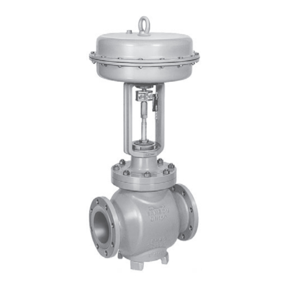
Page 15: Design And Principle Of Operation
See Fig. 3-1 on page 3-3. the flow rate through the valve. The Type 3251 Valve is a single-seated globe valve. This valve is preferably com- bined with a SAMSON Type 3271 or We recommend the use of positioners with Type 3277 Pneumatic Actuator. - Page 16 Design and principle of operation − Actuator stem extends (FA) When the signal pressure is reduced or the air supply fails, the springs move the actuator stem downward and close the valve. The valve opens when the signal pressure is increased enough to over- come the force exerted by the springs.
- Page 17 Design and principle of operation Connection for tem- perature sensor Fig. 3-1: Type 3251 Valve for molten salt service: with welding ends, bellows seal and Type 3271 Pneumatic Actuator (left) · Standard version with flanges (right) EB 8052-1 EN...
-
Page 18: Versions
In these instructions, the preferable combina- crystallizing. tion with a SAMSON Type 3271 or Type 3277 Pneumatic Actuator is described. Î Set the trace heating to keep the process The pneumatic actuator (with or without medium at least 50 °C (122 °F) above... -
Page 19: Valve Accessories
Noise reduction Noise emissions Trims with flow dividers can be used to re- SAMSON is unable to make general state- duce noise emission (see u T 8081). ments about noise emissions. The noise emis- sions depend on the valve version, plant fa- 3.3 Valve accessories... - Page 20 Type 3251 Valve. Table 3-6 to Table 3-9 provide an overview of the dimensions and weights of the Type 3251 Valve with bellows seal. The lengths and heights are defined in the dimensional drawings on page 3-7 and are based on a valve combined with a SAMSON Type 3271 or Type 3277 Actuator.
- Page 21 Class and larger 300-600 with foot) 2.76 3.05 3.94 4.33 4.72 7.09 9.25 Class 900 Dimensional drawings Type 3251 up to NPS 3 without Type 3251 in NPS 4 and larger Type 3251 Valve with bellows foot with foot seal and welding ends EB 8052-1 EN...
- Page 22 Design and principle of operation Table 3-3: Dimensions of Type 3251 Valve, NPS 8 and larger Valve – 21.38 26.50 29.00 35.00 40.00 Class 150 On request 1016 22.38 27.88 30.50 36.50 41.62 Length L Class 300 On request 1057 (flanges RF and weld- 24.00...
- Page 23 Class 900 On request NPS 10, Class 150 to 300: 17.40” or 442 mm NPS 10, Class 600 to 900: 20.43” or 519 mm H8 = 25.59“ or 650 mm with 250 mm seat bore Table 3-4: Weights for standard version of Type 3251, up to NPS 6 ½ 1½ Valve Class 150 Class 300...
- Page 24 Design and principle of operation Table 3-6: Dimensions of Type 3251 Valve with bellows seal, up to NPS 6 ½ 1½ Valve size Travel 14.25 14.25 14.72 23.94 24.13 24.13 27.72 Class 150 Height 0.59 to 2.36” 15 to 60 mm 14.25 14.25 14.72 23.94...
- Page 25 Design and principle of operation Table 3-9: Weights of Type 3251 Valve with bellows seal, NPS 8 and larger Valve size – 1146 2150 2227 Class 150 1010 1146 2150 2227 Class 300 Valve 1010 without On request 1312 2740 2734 actuator Class 600 1243...
- Page 26 3-12 EB 8052-1 EN...
-
Page 27: Shipment And On-Site Transport
2. Check the shipment for transportation Î Stay clear of suspended or moving damage. Report any damage to loads. SAMSON and the forwarding agent Î Close off and secure the transport paths. (refer to delivery note). 3. Determine the weight and dimensions of... -
Page 28: Transporting The Valve
Risk of personal injury due to the control A swivel hoist can be screwed into valve tipping over. SAMSON actuators with a female thread on Î Observe the valve's center of gravity. the top diaphragm case in place of the Î... -
Page 29: Lifting The Valve
Shipment and on-site transport 4.3.2 Lifting the valve − Protect the piping and any mounted valve accessories against damage. To install a large valve into the pipeline, use − Protect the control valve against moisture lifting equipment (e.g. crane or forklift) to lift and dirt. -
Page 30: Storing The Valve
Shipment and on-site transport − Make sure the slings can be removed 6. After installation in the pipeline, check from the valve once it has been installed whether the flanges are bolted tight and into the pipeline. the valve in the pipeline holds. −... - Page 31 Special storage instructions for elastomers packing before stroking the valve. Elastomer, e.g. actuator diaphragm Î Contact SAMSON in case of different − To keep elastomers in shape and to pre- storage conditions or longer storage vent cracking, do not bend them or hang times.
- Page 32 EB 8052-1 EN...
-
Page 33: Installation
Contact SAMSON if the actuator on top: lengths are significantly shorter than the rec- Î Contact SAMSON if the mounting posi- ommended lengths. tion is not as specified above. To ensure that the valve functions properly,... - Page 34 Installation Î Valves, which are not installed in the Vent plugs pipeline in the upright position with the Vent plugs are screwed into the exhaust air actuator on top, must be supported or ports of pneumatic and electropneumatic suspended. devices. They ensure that any exhaust air that forms can be vented to the atmosphere Valve accessories (to avoid excess pressure in the device).
-
Page 35: Preparation For Installation
Installation 5.2 Preparation for installation Î Make sure that the corresponding com- ponents are heated correctly. Before installation, make sure the following conditions are met: Î Flush the pipelines. − The valve is clean. Note − The valve and all valve accessories (in- cluding piping) are not damaged. -
Page 36: Mounting The External Anti-Rotation Fixture
Risk of valve damage due to the use of cording to Table 5-4. unsuitable tools. 6. Use a soft-faced hammer or lever press Î Only use tools approved by SAMSON to press the slider disks (309) with their (u AB 0100). beveled part first (without using any lu- bricant) into the recesses of the clamps 5.3.1... - Page 37 Installation Table 5-2: Tightening torques and their seating surface on the yoke on each side (see detailed view Y in Screw size Tightening torque Fig. 5-2). [Nm] – The anti-rotation fixture does not get stuck on the yoke and can move free- ly in the direction of travel.
- Page 38 Installation Plug stem Legend Stem Lubricant Gleitmo 1763 V Clamps Screws Washers Slider disks Fig. 5-2: Overview of anti-rotation fixture assembly in the standard version EB 8052-1 EN...
- Page 39 Installation b) Special version for valve 8. Thread the stem (9) upwards until the head of the stem rests on the extended sizes NPS 2 to 4 actuator stem. See Fig. 5-3 and Fig. 5-4 9. Retract the actuator stem to relieve the stem (9).
- Page 40 Installation Legend Yoke Screws Hanger Plug stem Travel indicator scale Castellated nut Warning label Holder Screws Washers Fig. 5-3: Overview of yoke assembly with travel indicator scale in the special version EB 8052-1 EN...
- Page 41 Installation Plug stem Legend Stem Lubricant Gleitmo 1763 V Clamps Screws Washers Slider disks Fig. 5-4: Overview of anti-rotation fixture assembly in the special version EB 8052-1 EN...
- Page 42 Installation Table 5-4: Mounting dimensions for Types 3271 and 3277 Pneumatic Actuators · See Fig. 5-5 for dimensional drawing Trav- Actuator Actuator preloading Dimension when the valve is closed [mm] [cm²] [mm] [mm] DN 50 to 100/NPS 2 to 4 · Special version 3.75 –...
- Page 43 Installation Trav- Actuator Actuator preloading Dimension when the valve is closed [mm] [cm²] [mm] [mm] DN 200 to 250/NPS 8 to 10 up to seat bore 200 · Standard version 1000 1400-60 87.5 1400-120 2800 5600 DN 250/NPS 10, seat bore 250 and DN 300 to 500/NPS 12 to 20 · Standard version 1000 1400-60 1400-120...
-
Page 44: Mounting The Actuator Onto The Valve
Installation Ball bearings (standard version only) Fig. 5-5: Dimensional drawing with mounting dimensions for Types 3271 and 3277 Pneumatic Actuators 5.3.2 Mounting the actuator tension. They can be identified by the long onto the valve bolts protruding from the bottom of the actu- ator. -
Page 45: Installing The Valve Into The Pipeline
Installation a) Mounting the actuator Depending on the version, SAMSON control valves are either delivered with the actuator already mounted on the valve or the valve Î To mount the actuator, proceed as de- and actuator are delivered separately. When... -
Page 46: Configuring The Temperature Control
Installation 5.4 Configuring the tempera- 2. Prepare the relevant section of the pipe- line for installing the valve. ture control 3. Remove the protective caps from the For molten salt service, the operating tem- valve ports before installing the valve. perature and the temperature of the valve 4. -
Page 47: Determining The Temperature Limits
Note Minimum temperature SAMSON can calculate the required heating The minimum temperature depends on the power on request for a specific application. melting point of the salt used. In turn, the melting point depends on the composition of the salt. - Page 48 Installation Î Drain the process medium from all the Î Do not impede the movement of the actu- plant sections concerned as well as the ator and plug stem by inserting objects valve. into the yoke. Î Before unblocking the actuator and plug stem after they have become blocked WARNING (e.g.
-
Page 49: Leak Test
Installation 5.5.1 Leak test NOTICE The plant operator is responsible for per- Impaired valve functioning due to increased forming the leak test and selecting the test friction as a result of the threaded bushing method. The leak test must comply with the being tightened too far. -
Page 50: Fail-Safe Position
Installation 5.5.3 Fail-safe position Î Shut off the signal pressure line. Î Check whether the valve moves to the fail-safe position (see the 'Design and principle of operation' section). 5.5.4 Pressure test The plant operator is responsible for per- forming the pressure test. Test medium It is possible to continue to use the packing after a pressure test using compressed air. -
Page 51: Start-Up
Start-up 6 Start-up WARNING The work described in this section is only to Fire risk due to molten salt. be performed by personnel appropriately Individual elements in molten salt (both in qualified to carry out such tasks. crystallized and liquefied state) can acceler- ate combustion or ignite on coming into con- tact with certain substances (e.g. - Page 52 Start-up or pneumatic valve accessories not fitted with Before start-up or putting the valve back into noise-reducing fittings. Both can damage service, make sure the following conditions hearing. are met: Î Wear hearing protection when working − The valve is properly installed into the near the valve.
-
Page 53: Operation
Operation 7 Operation WARNING Immediately after completing start-up or put- Fire risk due to molten salt. ting the valve back into operation, the valve Individual elements in molten salt (both in is ready for use. crystallized and liquefied state) can accelerate combustion or ignite on coming into contact with certain substances (e.g. -
Page 54: Normal Operation
Operation pneumatic actuator (see 'Fail-safe position') NOTICE or pneumatic valve accessories not fitted with Risk of damage to the valve and pipelines noise-reducing fittings. Both can damage due to the process medium crystallizing. hearing. The molten salt crystallizes when its tempera- Î... -
Page 55: Malfunctions
Malfunctions 8 Malfunctions Read hazard statements, warnings and caution notes in the 'Safety instructions and mea- sures' section. 8.1 Troubleshooting Malfunction Possible reasons Recommended action Actuator and plug stem Actuator is blocked. Check attachment. does not move on de- Remove the blockage. WARNING! A blocked actuator or plug stem (e.g. -
Page 56: Emergency Action
Malfunctions Malfunction Possible reasons Recommended action The valve leaks to the Defective packing Replace packing (see the 'Servicing' section) or atmosphere (fugitive contact our after-sales service. emissions). Version with adjustable Adjust the packing (see information under 'Adjust- packing : packing not ing the packing' in the 'Testing the installed valve' 2) tightened correctly... -
Page 57: Servicing
Servicing 9 Servicing is running. Risk of severe burn injuries if touched. The work described in this section is only to Î Prior to performing any work on the be performed by personnel appropriately valve, allow components and pipelines to qualified to carry out such tasks. - Page 58 Servicing WARNING WARNING WARNING Risk of poisoning from molten salt vapors. Crush hazard arising from actuator and Molten salt in the liquefied state produces plug stem moving. vapors that are toxic. Î Do not insert hands or finger into the Î...
-
Page 59: Periodic Testing
Risk of valve damage due to the use of intervals to prevent a possible failure before unsuitable tools. it can occur. SAMSON is unable to make Î Only use tools approved by SAMSON general statements about inspection (u AB 0100). - Page 60 If the packing leaks continuously and the medium has crystallized in the packing, replace the packing (see section 9.4) or contact SAMSON's After-sales Service (see the 'Repairs' section). Check the test connection and Approximately Put the control valve out of operation (see the...
- Page 61 If the medium has crystallized in the packing, replace the packing (see section 9.4) or con- tact SAMSON's After-sales Service (see the 'Re- pairs' section). Unblock a blocked actuator and plug stem. WARNING! A blocked actuator or plug stem (e.g.
- Page 62 Servicing Connection for tem- perature sensor Fig. 9-1: Type 3251 Valve for molten salt service: with welding ends, bellows seal and Type 3271 Pneumatic Actuator (left) · Standard version with flanges (right) EB 8052-1 EN...
-
Page 63: Preparing The Valve For Service Work
Servicing Legend for Fig. 9-1 Body Body nut Diaphragm Bonnet Packing Actuator stem Yoke Body gasket Ring nut Seat Bellows seal A10 Spring Plug Plug stem with bellows A16 Vent plug seal Threaded bushing A26 Stem connector clamps (packing nut) Test connection Signal pressure con- Stem connector nut Travel indicator scale... -
Page 64: Service Work
Servicing 9.4 Service work a) Standard version 1. Undo the body nuts (14) gradually in a NOTICE crisscross pattern. Risk of damage to the valve and pipelines 2. Lift the bonnet (2) and plug with plug due to the process medium crystallizing. stem (5) off the body (1). -
Page 65: Replacing The Packing
Servicing Version with V-port plug: place the 5. Unscrew the threaded bushing (8). bellows seal (22) onto the valve body, 6. Pull the plug with plug stem (5) out of the making sure that the largest V-shaped bonnet (2). port of the V-port plug faces toward the 7. -
Page 66: Replacing The Seat And Plug
Servicing 9.4.3 Replacing the seat and 12. Firmly press the plug (5) into the seat (4). Fasten down the bonnet (2) with the plug body nuts (14). Tighten the nuts gradual- ly in a crisscross pattern. Observe tight- NOTICE ening torques. Risk of control valve damage due to incor- 13. -
Page 67: Cleaning The Pipelines
Servicing 13. Slide the new plug with plug stem (5) in- NOTICE to the bonnet (2). Risk of damage to the facing of the seat 14. Place the bonnet (2) together with the and plug due to incorrect servicing. plug stem and plug (5) onto the body Î... -
Page 68: Ordering Spare Parts And Operating Supplies
See section 9.4.2. 9.6 Ordering spare parts and operating supplies Contact your nearest SAMSON subsidiary or SAMSON's After-sales Service for infor- mation on spare parts, lubricants and tools. Spare parts See Annex for details on spare parts. Lubricant See document u AB 0100 for details on... -
Page 69: Decommissioning
Decommissioning 10 Decommissioning DANGER The work described in this section is only to Risk of burn injuries from molten salt. be performed by personnel appropriately Molten salt reaches very high temperatures qualified to carry out such tasks. of over 200 °C (392 °F) and leads to severe burn injuries if touched. - Page 70 Decommissioning Î Make sure the area is sufficiently Î Do not impede the movement of the actu- ventilated. ator and plug stem by inserting objects Î Wear a respirator. into the yoke. Î Before unblocking the actuator and plug stem after they have become blocked WARNING (e.g.
- Page 71 Decommissioning 5. Rinse the pipelines and valve to remove WARNING WARNING any residual medium. Observe the notes Risk of personal injury due to residual pro- on cleaning the pipelines (see informa- cess medium in the valve. tion under 'Cleaning the pipelines' in the While working on the valve, residual me- 'Servicing' section).
- Page 72 10-4 EB 8052-1 EN...
-
Page 73: Removal
Removal 11 Removal release any stored energy in the actuator (e.g. spring compression). See The work described in this section is only to associated actuator documentation. be performed by personnel appropriately qualified to carry out such tasks. WARNING WARNING DANGER Risk of personal injury due to residual Risk of burn injuries due to hot components process medium in the valve. -
Page 74: Removing The Valve From The Pipeline
Removal 11.1 Removing the valve from the pipeline a) Version with flanges 1. Support the valve to hold it in place when separated from the pipeline (see the 'Shipment and on-site transport' sec- tion). 2. Unbolt the flange joint. 3. Remove the valve from the pipeline (see the 'Shipment and on-site transport' sec- tion). -
Page 75: Repairs
Î Do not perform any repair work on your outside of your shipment so that the own. documents are clearly visible. Î Contact SAMSON's After-sales Service 4. Send the shipment to the address given for repair work. on the RMA. - Page 76 12-2 EB 8052-1 EN...
-
Page 77: Disposal
Disposal 13 Disposal Î Observe local, national and internation- al refuse regulations. Î Do not dispose of components, lubricants and hazardous substances together with your household waste. Note The supplier of the molten salt provides in- structions on the correct disposal of molten salt used in the plant. - Page 78 13-2 EB 8052-1 EN...
-
Page 79: Certificates
Country of origin: France, see page 14-3 to 14-4 − Declaration of conformity in compliance with Machinery Directive 2006/42/EC for Types 3251-1 and 3251-7 Control Valves on page 14-5 − Declaration of incorporation in compli- ance with Machinery Directive 2006/42/EC for the Type 3251 Valve with other actuators other than Types 3271 and 3277 Actuators on... - Page 80 14-2 EB 8052-1 EN...
- Page 81 BNP Paribas N° compte 0002200215245 • Banque 3000401857 Tél.: +33 (0)4 72 04 75 00 • Fax: +33 (0)4 72 04 75 75 • E-mail: samson@samson.fr • Internet: www.samson.fr IBAN FR7630004018570002200215245 • BIC (code SWIFT) BNPAFRPPVBE Société par actions simpifiée au capital de 10 000 000 € • Siège social : Vaulx-en-Velin Crédit Lyonnais...
- Page 82 BNP Paribas N° compte 0002200215245 • Banque 3000401857 Tél.: +33 (0)4 72 04 75 00 • Fax: +33 (0)4 72 04 75 75 • E-mail: samson@samson.fr • Internet: www.samson.fr IBAN FR7630004018570002200215245 • BIC (code SWIFT) BNPAFRPPVBE Société par actions simpifiée au capital de 10 000 000 € • Siège social : Vaulx-en-Velin Crédit Lyonnais...
- Page 83 EB 8052-1 EN 14-5...
- Page 84 14-6 EB 8052-1 EN...
-
Page 85: Annex
Annex 15 Annex 15.1 Tightening torques, lubricants and tools u AB 0100 for tools, tightening torques and lubricants 15.2 Spare parts Body 42/43 Screw plug with seal Bonnet Flow divider ST 1 Yoke Ring 1) Seat Gasket 1) Plug Gasket 1) Bellows nut Nameplate Guide bushing Grooved pin... - Page 86 80 81 80 81 83 42/43 12.1 12.1 15-2 EB 8052-1 EN...
-
Page 87: After-Sales Service
You can reach our after-sales service at aftersalesservice@samsongroup.com. Addresses of SAMSON AG and its subsid- iaries The addresses of SAMSON AG, its subsid- iaries, representatives and service facilities worldwide can be found on our website (www.samsongroup.com) or in all SAMSON product catalogs. - Page 88 15-4 EB 8052-1 EN...
- Page 92 EB 8052-1 EN SAMSON AKTIENGESELLSCHAFT Weismüllerstraße 3 · 60314 Frankfurt am Main, Germany Phone: +49 69 4009-0 · Fax: +49 69 4009-1507 samson@samsongroup.com · www.samsongroup.com...
Need help?
Do you have a question about the 3251 and is the answer not in the manual?
Questions and answers