
Related Manuals for Samson 3259


Summary of Contents for Samson 3259
- Page 1 EB 8059 EN Translation of original instructions Type 3259 Valve In combination with an actuator, e.g. a SAMSON Type 3271 or Type 3277 Pneumatic Actuator Edition December 2017...
- Page 2 Î For the safe and proper use of these instructions, read them carefully and keep them for later reference. Î If you have any questions about these instructions, contact SAMSON‘s After-sales Service Department (aftersalesservice@samson.de). The mounting and operating instructions for the devices are included in the scope of delivery.
-
Page 3: Table Of Contents
Contents Safety instructions and measures ..............5 Notes on possible severe personal injury ............8 Notes on possible personal injury ..............8 Notes on possible property damage ..............9 Markings on the device ................12 Valve nameplate ..................12 Actuator nameplate ..................13 Material number ..................13 Design and principle of operation ..............14 Fail-safe positions ..................14 Versions ......................16 Technical data .....................16... - Page 4 Contents Servicing.....................34 Preparing the valve for servicing ..............35 Replacing the body gasket ................35 7.2.1 Standard version..................35 7.2.2 Version with insulating section ...............37 7.2.3 Version with bellows seal ................37 Replacing the packing ..................38 7.3.1 Standard version..................38 7.3.2 Version with insulating section ...............40 Replacing the seat and plug ................41 7.4.1 Standard version..................41...
-
Page 5: Safety Instructions And Measures
In case operators intend to use the control valve in other applications or conditions than specified, contact SAMSON. SAMSON does not assume any liability for damage resulting from the failure to use the de- vice for its intended purpose or for damage caused by external forces or any other external factors. - Page 6 Î Check with the plant operator for details on further protective equipment. Revisions and other modifications Revisions, conversions or other modifications of the product are not authorized by SAMSON. They are performed at the user's own risk and may lead to safety hazards, for example. Fur- thermore, the product may no longer meet the requirements for its intended use.
- Page 7 Safety instructions and measures Responsibilities of operating personnel Operating personnel must read and understand these mounting and operating instructions as well as the referenced documents and observe the specified hazard statements, warnings and caution notes. Furthermore, the operating personnel must be familiar with the applicable health, safety and accident prevention regulations and comply with them.
-
Page 8: Notes On Possible Severe Personal Injury
Safety instructions and measures 1.1 Notes on possible severe personal injury DANGER Risk of bursting in pressure equipment. Valves and pipelines are pressure equipment. Improper opening can lead to valve components bursting. Î Before starting any work on the valve, depressurize all plant sections concerned as well as the valve. -
Page 9: Notes On Possible Property Damage
Risk of personal injury due to preloaded springs. Valves in combination with pneumatic actuators with preloaded springs are under ten- sion. These control valves with SAMSON pneumatic actuators can be identified by the long bolts protruding from the bottom of the actuator. - Page 10 Risk of valve damage due to the use of unsuitable tools. Certain tools are required to work on the valve. Î Only use tools approved by SAMSON (u AB 0100). Risk of valve damage due to the use of unsuitable lubricants. The lubricants to be used depend on the valve material. Unsuitable lubricants may corrode and damage the valve surface.
- Page 11 EB 8059 EN...
-
Page 12: Markings On The Device
Markings on the device 2 Markings on the device 2.1 Valve nameplate SAMSON Fig. 1: Valve nameplate 1…5 14 15 16 17 1…5 PED (Pressure Equipment Directive), "Art. 4, Abs. 3" ID of the notified body, fluid group and category Type designation... -
Page 13: Actuator Nameplate
Markings on the device The nameplate (80) is affixed to the yoke of the valve (see Fig. 2). Fig. 2: Valve nameplate 2.2 Actuator nameplate See associated actuator documentation. 2.3 Material number The seat and plug of the valves have an arti- cle number written on them. -
Page 14: Design And Principle Of Operation
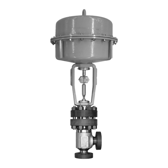
As a result, the plug position in the seat changes and determines ation the flow rate through the valve. The Type 3259 High-pressure Angle Valve is 3.1 Fail-safe positions preferably combined with a SAMSON Type 3271 or Type 3277 Pneumatic Actuator The fail-safe position depends on the mount- (see Fig. 3). - Page 15 Design and principle of operation A26/27 Fig. 3: Type 3259 Valve with Type 3271 Pneumatic Actuator (left) and Type 3277 Pneumatic Actuator (right) EB 8059 EN...
-
Page 16: Versions
Dimensions and weights Table 2 to Table 4 contain the dimensions Note and weights for Type 3259. The lengths and If the travel range of the actuator is larger heights in the dimension diagrams are than the travel range of the valve, the spring shown on page 19. - Page 17 Body with Bellows seal –10 to +450 °C Leakage class according to IEC 60534‑4 Valve plug Metal seal IV · High-performance metal seal: V Table 2: Dimensions and weights for standard version of Type 3259 Valve Valve size Length L 350 cm² – 355v2 cm² –...
- Page 18 Design and principle of operation Table 3: Dimensions and weights for Type 3259 with insulating section Valve size 350 cm² – 355v2 cm² – 700 cm² 1175 1175 750v2 cm² 1175 1175 H4 for 1000 cm² actuator 1175 1175 1400-60 cm² 1400-120 cm² – 1050 1050 1260 1260 2800 cm²...
- Page 19 Type 3259 with insulating Type 3259 with bellows seal section Note The associated actuator documentation applies to actuators, e.g. for SAMSON pneumatic actuators: u T 8310‑1 for Type 3271 and Type 3277 Actuators up to 750v2 cm² actuator area u T 8310‑2 for Type 3271 Actuator with 1000 cm² actuator area and larger u T 8310‑3 for Type 3271 Actuator with 1400‑60 cm²...
-
Page 20: Measures For Preparation
2. Check the shipment for transportation WARNING damage. Report any damage to Risk of lifting equipment tipping and risk of SAMSON and the forwarding agent damage to lifting accessories due to exceed- (refer to delivery note). ing the rated lifting capacity. -
Page 21: Transporting
The control valve can be transported using tached slings. lifting equipment (e.g. crane or forklift). The welded‑on lifting eyelet on SAMSON Î Leave the control valve in its transport actuators is only intended for mounting and container or on the pallet to transport it. -
Page 22: Lifting
Measures for preparation 4.2.2 Lifting − Do not leave loads suspended when in- terrupting work for longer periods of To install a large valve into the pipeline, use time. lifting equipment (e.g. crane or forklift) to lift Lifting instructions We recommend using a hook with safety latch (see Fig. 4). - Page 23 Measures for preparation Lifting the control valve in the horizontal 4. Install the control valve into the pipeline. position 5. After installation in the pipeline, check The control valve can be lifted in the hori- whether the weld seams hold. zontal position either using one hook (Fig. 4) 6.
- Page 24 Measures for preparation Lifting the control valve in the upright posi- tion The control valves can also be lifted in the upright position (see Fig. 6). On lifting the control valve in the upright position, make sure the following conditions are met: −...
-
Page 25: Storage
− Observe storage instructions. − Do not place any objects on the control − Avoid long storage times. valve. − Contact SAMSON in case of different stor- Special storage instructions for elastomers age conditions or long storage periods. Elastomer, e.g. actuator diaphragm −... - Page 26 Measures for preparation Î Check to make sure that the type desig- nation, valve size, material, pressure rat- ing and temperature range of the valve match the plant conditions (size and pressure rating of the pipeline, medium temperature etc.). Î Check any mounted pressure gauges to make sure they function.
-
Page 27: Mounting And Start-Up
The process medium in the valve flows through the V-shaped ports as soon as the SAMSON valves are delivered ready for plug is lifted out of the seat (i.e. the valve use. In special cases, the valve and actuator opens). -
Page 28: Installing The Valve Into The Pipeline
− Valves with insulating section for low sure that they can be operated from the temperatures below –10 °C workplace of the operating personnel. Î Contact SAMSON if the mounting posi- tion is not as specified above. Note Support or suspension... -
Page 29: Additional Fittings
Additional fittings Safety guard To reduce the crush hazard arising from Strainers moving parts (actuator and plug stem), a We recommend installing a SAMSON safety guard can be installed. strainer upstream of the valve. It prevents sol- 5.2.3 Installing the control id particles in the process medium from damaging the valve. -
Page 30: Quick Check
Adjustable packing 5.3 Quick check SAMSON valves are delivered ready for use. To test the valve's ability to function, the A label on the yoke (3) indicates whether an following quick checks can be performed: adjustable packing is installed. - Page 31 − Observe the maximum permissible pres- sure for valve and plant. Note The plant operator is responsible for performing the pressure test. SAMSON's After‑sales Service department can support you to plan and perform a pressure test for your plant. EB 8059 EN...
-
Page 32: Operation
Operation 6 Operation 6.1 Working in manual mode The valve is ready for use when mounting Valves fitted with actuators with a handwheel and start-up (see section 5) have been com- can be manually closed or opened in case of pleted. supply air failure. - Page 33 EB 8059 EN...
-
Page 34: Servicing
Risk of valve damage due to the use of un- While working on the valve, residual process suitable tools. medium can escape and, depending on its Only use tools approved by SAMSON properties, may lead to personal injury, e.g. (u AB 0100). (chemical) burns. -
Page 35: Preparing The Valve For Servicing
(1) and on the intermediate piece (2). Note The control valve was checked by SAMSON 5. Apply a suitable lubricant to the new before it left the factory. body gasket (17) and insert it into the −... -
Page 36: Seat
92 Castellated nut 5 Plug 15 Packing 111 Threaded flange 7 Guide bushing 17 Body gasket (lens ring gasket) 8 Threaded bushing (packing nut) 21 Insulating section Fig. 7: Standard version of Type 3259 (left) and with insulating section (right) EB 8059 EN... -
Page 37: Version With Insulating Section
Servicing 7.2.2 Version with insulating 10. Adjust lower or upper signal bench range. See associated actuator docu- section mentation. 1. Remove the actuator from the valve. See 7.2.3 Version with bellows associated actuator documentation. seal 2. Undo the body nuts (14) gradually in a crisscross pattern. -
Page 38: Replacing The Packing
(5). is installed in the valve. To replace the packing in other valve ver- 13. Slide the plug with plug stem (5) into the sions, contact SAMSON's After‑sales Service intermediate piece (2). department. 14. Push the intermediate piece (2) together with the plug (5) into the body (1). - Page 39 Servicing making sure that the largest V-shaped 19. Place yoke (3) on the intermediate piece port of the V-port plug faces toward the (2) and fasten tight using the castellated valve outlet. See section 5.1. nut (92). 15. Carefully slide the packing parts over the 20.
-
Page 40: Version With Insulating Section
Servicing 7.3.2 Version with insulating er and that their bolt holes are aligned exactly above one another. section Version with V‑port plug: place the insu- 1. Remove the actuator from the valve. See lating section (21) onto the valve body, associated actuator documentation. -
Page 41: Replacing The Seat And Plug
9. Make sure that the guide bushing (7) is To replace seat and plug in other valve ver- not damaged. If necessary, replace the sions, contact SAMSON's After‑sales Service guide bushing using a suitable tool. department. 10. Pull all the packing parts out of the pack- ing chamber using a suitable tool. -
Page 42: Threaded Bushing (Packing Nut)
92 Castellated nut 5 Plug 15 Packing 111 Threaded flange 7 Guide bushing 17 Body gasket (lens ring gasket) 8 Threaded bushing (packing nut) 21 Insulating section Fig. 9: Standard version of Type 3259 (left) and with insulating section (right) EB 8059 EN... -
Page 43: Version With Insulating Section
Servicing Version with V‑port plug: place the in- 3. Undo the body nuts (14) gradually in a termediate piece (2) onto the valve body, crisscross pattern. Remove the bolts (13). making sure that the largest V-shaped 4. Pull the insulating section (21) together port of the V-port plug faces toward the with the plug (5) out of the body (1). -
Page 44: Preparation For Return Shipment
18. Insert the bolts (13) through the threaded 4. Send the valve together with the filled-in flanges (57, 111) and tighten them, ob- form to your nearest SAMSON subsidi- serving the tightening torque. ary. SAMSON subsidiaries are listed on 19. Tighten the body nuts (14) gradually in a our website at u www.samson.de >... - Page 45 Servicing EB 8059 EN...
-
Page 46: Malfunctions
Depending on the operating conditions, check the valve at certain intervals to prevent possi- ble failure before it can occur. Operators are responsible for drawing up an inspection plan. SAMSON's After‑sales Service department can support you to draw up an inspection plan for your plant. -
Page 47: Emergency Action
A label on the yoke (3) indicates whether an adjustable packing is installed. Note Contact SAMSON's After‑sales Service department for malfunctions not listed in the table. 8.2 Emergency action Upon supply air or control signal failure, the valve moves to its fail-safe position (see sec- tion 3.1). -
Page 48: Decommissioning And Disassembly
Decommissioning and disassembly 9 Decommissioning and disas- 9.1 Decommissioning sembly To decommission the control valve for service and repair work or disassembly, proceed as follows: DANGER Risk of bursting in pressure equipment. 1. Close the shut-off valves upstream and Valves and pipelines are pressure equip- downstream of the control valve to stop ment. -
Page 49: Annex
You can reach the After-sales Service De- partment at aftersalesservice@samson.de. Addresses of SAMSON AG and its subsid- iaries The addresses of SAMSON AG, its subsid- iaries, representatives and service facilities worldwide can be found on the SAMSON website (www.samson.de) or in all SAMSON product catalogs. - Page 50 Modul H/Module H / N° CE-0062-PED-H-SAM 001-16-DEU-rev-A SAMSON erklärt in alleiniger Verantwortung für folgende Produkte:/For the following products, SAMSON hereby declares under its sole resposibility: Geräte/Devices Bauart/Series Typ/Type Ausführung/Version DIN, Gehäuse GG ab DN 150, Gehäuse GGG ab DN 100, Fluide G2, L1, L2...
- Page 51 EB 8059 EN...
-
Page 52: Spare Parts
Annex 10.3 Spare parts Body Plug stem with metal bellows Intermediate piece Gasket Seat Screw plug Plug (with plug stem) Seal Bellows nut Threaded flange Guide bushing Threaded flange Threaded bushing (packing nut) Threaded flange Stem connector nut Yoke assembly Lock nut Nameplate Spring... - Page 53 EB 8059 EN...
- Page 54 EB 8059 EN...
- Page 55 EB 8059 EN...
- Page 56 EB 8059 EN SAMSON AKTIENGESELLSCHAFT Weismüllerstraße 3 · 60314 Frankfurt am Main, Germany Phone: +49 69 4009-0 · Fax: +49 69 4009-1507 samson@samson.de · www.samson.de...
Need help?
Do you have a question about the 3259 and is the answer not in the manual?
Questions and answers