Samson 3251 Mounting And Operating Instructions
Hide thumbs
Also See for 3251:
- Mounting and operating instructions (108 pages) ,
- Mounting and operating instructions (60 pages) ,
- Mounting and operating instructions (92 pages)

Related Manuals for Samson 3251


Summary of Contents for Samson 3251
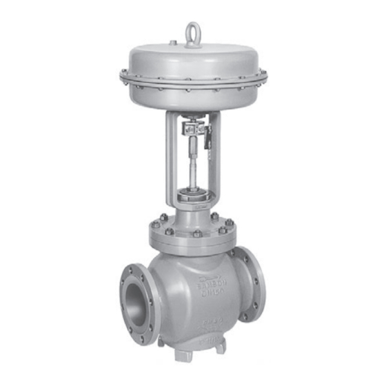
- Page 1 Type 3251 Valve In combination with an actuator, e.g. a SAMSON Type 3271 or Type 3277 Pneumatic Actuator ANSI version Type 3251 Valve with Type 3271 Actuator Mounting and Operating Instructions EB 8052 EN Edition July 2016...
- Page 2 Î For the safe and proper use of these instructions, read them carefully and keep them for later reference. Î If you have any questions about these instructions, contact SAMSON‘s After-sales Service Department (aftersalesservice@samson.de). The mounting and operating instructions for the devices are included in the scope of delivery.
-
Page 3: Table Of Contents
Contents Safety instructions and measures ..............5 Notes on possible severe personal injury ............8 Notes on possible personal injury ..............8 Notes on possible property damage ..............9 Markings on the control valve ..............12 Valve nameplate ..................12 Actuator nameplate ..................13 Material number ..................13 Design and principle of operation ..............14 Fail-safe positions ..................14 Versions ......................16... - Page 4 Contents Replacing the packing ..................41 7.2.1 Standard version..................41 7.2.2 Version with insulating section ...............43 Replacing the seat and plug ................45 7.3.1 Standard version..................47 7.3.2 Version with insulating section ...............48 Preparation for return shipment ..............49 Ordering spare parts and operating supplies ..........49 Malfunctions ....................50 Troubleshooting ...................50 Emergency action ..................51...
-
Page 5: Safety Instructions And Measures
SAMSON. SAMSON does not assume any liability for damage resulting from the failure to use the valve for its intended purpose or for damage caused by external forces or any other external factors. - Page 6 Î Check with the plant operator for details on further protective equipment. Revisions and other modifications Revisions, conversions or other modifications to the product are not authorized by SAMSON. They are performed at the user's own risk and may lead to safety hazards, for example.
- Page 7 The following documents apply in addition to these mounting and operating instructions: − Mounting and operating instructions for mounted actuator, e.g. u EB 8310-X for SAMSON Type 3271 and Type 3277 Actuators − Mounting and operating instructions for mounted valve accessories (positioner, solenoid valve etc.) −...
-
Page 8: Notes On Possible Severe Personal Injury
Safety instructions and measures 1.1 Notes on possible severe personal injury DANGER Risk of bursting in pressure equipment. Control valves and pipelines are pressure equipment. Improper opening can lead to valve components bursting. Î Before starting any work on the control valve, depressurize all plant sections concerned as well as the valve. -
Page 9: Notes On Possible Property Damage
Risk of personal injury due to preloaded springs. Valves in combination with pneumatic actuators with preloaded springs are under ten- sion. These control valves with SAMSON pneumatic actuators can be identified by the long bolts protruding from the bottom of the actuator. - Page 10 Risk of valve damage due to the use of unsuitable lubricants. The lubricants to be used depend on the valve material. Unsuitable lubricants may cor- rode and damage the valve surface. Î Only use lubricants approved by SAMSON (see parts list). EB 8052 EN...
- Page 11 EB 8052 EN...
-
Page 12: Markings On The Control Valve
Markings on the control valve 2 Markings on the control valve 2.1 Valve nameplate SAMSON Fig. 1: Valve nameplate 1…5 14 15 16 17 18 1…5 PED (Pressure Equipment Directive), "Art. 4, Abs. 3" ID of the notified body, fluid group, and category... -
Page 13: Actuator Nameplate
Markings on the control valve The nameplate (80) is affixed to the yoke of the valve (see Fig. 2). Fig. 2: Location of the nameplate 2.2 Actuator nameplate See associated actuator documentation. 2.3 Material number The seat and plug of the valves have an arti- cle number written on them. -
Page 14: Design And Principle Of Operation
When the signal pressure is reduced or the air supply fails, the springs move the actua- The single-seated Type 3251 Globe Valve is tor stem downward and close the valve. The preferably combined with a SAMSON valve opens when the signal pressure is in- Type 3271 or Type 3277 Pneumatic Actuator... - Page 15 Travel indicator scale Plug (with plug stem) Vent plug Castellated nut Threaded bushing Stem connector clamps Actuator (packing nut) Signal pressure Diaphragm Stem connector nut connection Fig. 3: Type 3251 Valve with Type 3271 Pneumatic Actuator (left) and Type 3277 Pneumatic Actuator (right) EB 8052 EN...
-
Page 16: Versions
Design and principle of operation 3.2 Versions Compliance The Type 3251 Valve bears both the CE and The modular design allows an insulating sec- EAC marks of conformity. tion or metal bellows to be fitted to the stan- dard valve version. - Page 17 Design and principle of operation Noise emission SAMSON is unable to make general statements about noise emission as it depends on the valve version, plant facilities, and process medium. On request, SAMSON can perform calculations according to IEC 60534, Part 8-3 and Part 8-4 or VDMA 24422 (edition 89).
- Page 18 Dimensions and weights Table 1 to Table 3 provide a summary of the dimensions and weights of the standard version of Type 3251 Valve. The lengths and heights in the dimensional drawings are shown on p. 19. Table 1: Dimensions of Type 3251 Valve, up to NPS 6 ½...
- Page 19 Class 900 with foot) 2.76 3.05 3.94 4.33 5.51 8.66 11.22 Class 1500 2.95 3.54 4.33 4.72 9.33 12.6 Class 2500 Dimensional drawings Type 3251 up to NPS 3 without foot Type 3251 in NPS 4 and larger with foot EB 8052 EN...
- Page 20 Design and principle of operation Table 2: Dimensions of Type 3251 Valve, NPS 8 and larger Valve – 21.38 26.50 29.00 35.00 40.00 Class 150 On request 1016 22.38 27.88 30.50 36.50 41.62 Class 300 On request 1057 Length L 24.00 29.62 32.25 38.25...
- Page 21 Design and principle of operation Valve – 16.46 1000 cm² On request 16.46 1400- On request 60 cm² 19.80 19.80 25.59 25.59 25.59 25.59 H8 for 1400- actuator 120 cm² 3) 19.80 19.80 25.59 25.59 25.59 25.59 2800 cm² 3) 19.80 19.80 25.59 25.59 25.59 25.59 2x2800 cm²...
- Page 22 Class 600 without actua- Class 900 1235 On re- Class 1500 quest 2198 On re- Class 2500 quest Table 4: Weights for standard version of Type 3251 in NPS 8 and larger Valve 1892 2028 3197 3638 On re- Class 150 quest 1450 1650 1892...
- Page 23 Refer to the following data sheets for more dimensions and weights: u T 8052 for valves with bellows seal, insulating section or heating jacket The associated actuator documentation applies to actuators, e.g. for SAMSON pneumatic actuators: u T 8310‑1 for Type 3271 and Type 3277 Actuators up to 750 cm² actuator area u T 8310‑2 for Type 3271 Actuator with 1000 cm²...
-
Page 24: Measures For Preparation
2. Check the shipment for transportation WARNING damage. Report any damage to Risk of lifting equipment tipping and risk of SAMSON and the forwarding agent damage to lifting accessories due to exceed- (refer to delivery note). ing the rated lifting capacity. -
Page 25: Transporting
The control valve can be transported using tached slings. lifting equipment (e.g. crane or forklift). The welded‑on lifting eyelet on SAMSON Î Leave the control valve in its transport actuators is only intended for mounting and container or on the pallet to transport it. - Page 26 Measures for preparation − Prevent the control valve from tilting or ed. Before lifting the control valve, tight- tipping. en the sling. − Do not leave loads suspended when in- terrupting work for longer periods of time. − Make sure that the axis of the pipeline is always horizontal during lifting and the axis of the plug stem is always vertical.
- Page 27 Measures for preparation Version with flanges Version with welding ends 1. Attach one sling to each flange of the 1. Attach one sling to each welding end of body and to the rigging equipment (e.g. the body and to the rigging equipment hook) of the crane or forklift (see Fig. 4).
-
Page 28: Storage
− Observe storage instructions. − Do not place any objects on the control − Avoid long storage times. valve. − Contact SAMSON in case of different Special storage instructions for elastomers storage conditions or long storage periods. Elastomer, e.g. actuator diaphragm −... -
Page 29: Preparation For Installation
Measures for preparation 4.4 Preparation for installation Proceed as follows: Î Flush the pipelines. Note The plant operator is responsible for clean- ing the pipelines in the plant. Î Check the valve to make sure it is clean. Î Check the valve for damage. Î... -
Page 30: Mounting And Start-Up
Mounting and start-up 5 Mounting and start-up 5.1 Mounting the actuator onto the valve SAMSON valves are delivered ready for use. In special cases, the valve and actuator Proceed as described in the actuator docu- are delivered separately and must be assem- mentation if the valve and actuator have not bled on site. -
Page 31: Installing The Valve Into The Pipeline
(see − Valves with insulating section for low associated actuator documentation). temperatures below –10 °C (14 °F) Î Contact SAMSON if the mounting posi- 5.2 Installing the valve into the tion is not as specified above. pipeline Support or suspension 5.2.1... - Page 32 Mounting and start-up Table 5: Inlet and outlet lengths Flow rate Inlet length Outlet length a x NPS b x NPS State of process Inlet length Outlet length Valve conditions medium Ma ≤ 0.3 0.3 ≤ Ma ≤ 0.7 Ma ≤ 0.3 1) 0.3 ≤ Ma ≤ 0.7 1) Vapor Saturated steam (percentage of condensate > 5 %) Free of cavitation/w < 10 m/s Cavitation producing noise/w ≤ 3 m/s...
-
Page 33: Additional Fittings
WARNING Risk of personal injury due to pressurized Strainers components and process medium escaping We recommend installing a SAMSON under pressure. strainer upstream of the valve. It prevents sol- Do not loosen the screw of the test connec- id particles in the process medium from tion while the valve is in operation. -
Page 34: Quick Check
5.3 Quick check to reach ambient temperature before start up. SAMSON valves are delivered ready for 7. Slowly open the shut-off valve in the use. To test the valve's ability to function, the pipeline after the valve has been in- following quick checks can be performed: stalled. - Page 35 A label on the flange (2) indicates whether The plant operator is responsible for an adjustable packing is installed. performing the pressure test. SAMSON's After‑sales Service department can support 1. Tighten the threaded bushing gradually you to plan and perform a pressure test for (by turning it clockwise) until the packing your plant.
-
Page 36: Operation
Operation 6 Operation 6.1 Working in manual mode Immediately after completing mounting and Valves fitted with actuators with a handwheel start-up (see section 5), the valve is ready for can be manually closed or opened in case of use. supply air failure. Î... - Page 37 EB 8052 EN...
-
Page 38: Servicing
Risk of valve damage due to the use of un- While working on the valve, residual process suitable tools. medium can escape and, depending on its Only use tools approved by SAMSON properties, may lead to personal injury, e.g. (u WA 0029). (chemical) burns. -
Page 39: Replacing The Gasket
Note − The valve size is ≤NPS 4. The control valve was checked by SAMSON − The valve does not have a balanced plug. before it left the factory. − The valve does not have a flow divider. - Page 40 5 Plug (with plug stem) 17 Body gasket 7 Guide bushing 21 Insulating section 8 Threaded bushing 92 Castellated nut (packing nut) Fig. 5: Standard version of Type 3251 with Type 3271 Actuator (left) and Type 3251 in version with insulating section (right) EB 8052 EN...
-
Page 41: Version With Insulating Section Or Bellows Seal
3. Lift the insulating section (21) and plug To replace the packing in other valve ver- with plug stem (5) off the body (1). sions, contact SAMSON's After‑sales Service 4. Remove the gasket (17). Carefully clean department. the sealing faces in the valve body (1) and on the insulating section (21). - Page 42 Servicing 7. Pull the plug with plug stem (5) out of the 19. Adjust lower or upper signal bench flange (2). range. See associated actuator docu- mentation. 8. Pull all the packing parts out of the pack- ing chamber using a suitable tool. ADSEAL packing 9.
-
Page 43: Version With Insulating Section
Servicing 8 Threaded bushing 11 Spring 12 Washer 16 Packing ring 19 Spacer Fig. 6: Standard packing: NPS ½ to 1½ (left) and NPS 2 to 4 (right) 7.2.2 Version with insulating 6. Unscrew the threaded bushing (8). section 7. Pull the plug with plug stem (5) out of the insulating section (21). - Page 44 Servicing 15.1 15.1 15.2 15.2 8 Threaded bushing 15.2 Seal 11 Spring 16 Packing ring 12 Washer 18 Bushing 15 Packing (entire) 19 Spacer 15.1 Shim with retaining ring Fig. 7: ADSEAL packing: NPS ½ to 1½ (left) and NPS 2 to 4 (right) EB 8052 EN...
-
Page 45: Replacing The Seat And Plug
To replace seat and plug in other valve ver- ADSEAL packing sions, contact SAMSON's After‑sales Service 1. Proceed as described in Standard pack- department. ing (PTFE), steps 1 to 12. 2. Carefully slide the packing parts over the... - Page 46 5 Plug (with plug stem) 17 Body gasket 7 Guide bushing 21 Insulating section 8 Threaded bushing 92 Castellated nut (packing nut) Fig. 8: Standard version of Type 3251 with Type 3271 Actuator (left) and Type 3251 in version with insulating section (right) EB 8052 EN...
-
Page 47: Standard Version
Servicing 14. Apply a suitable lubricant to all the pack- ing parts and to the new plug stem (5). When replacing the seat and plug, we also We recommend replacing the packing as recommend replacing the packing. See sec- well. See section 7.2.1. tion 7.2. -
Page 48: Version With Insulating Section
Servicing 7.3.2 Version with insulating 15. Slide the new plug with plug stem (5) in- to the insulating section (21). section 16. Place the insulating section (21) together 1. Remove the actuator from the valve. See with the plug stem and plug (5) onto the associated actuator documentation. -
Page 49: Preparation For Return Shipment
> Services > Check lists for after sales service > Declaration on Contamination. 4. Send the valve together with the filled-in form to your nearest SAMSON subsidi- ary. SAMSON subsidiaries are listed on our website at u www.samson.de > Contact. -
Page 50: Malfunctions
Depending on the operating conditions, check the valve at certain intervals to prevent possi- ble failure before it can occur. Operators are responsible for drawing up an inspection plan. SAMSON's After‑sales Service department can support you to draw up an inspection plan for your plant. -
Page 51: Emergency Action
SAMSON's After-sales Service department). A label on the flange (2) indicates whether an adjustable packing is installed. Note Contact SAMSON's After‑sales Service department for malfunctions not listed in the table. 8.2 Emergency action Putting the valve back into operation after a malfunction Upon supply air or control signal failure, the Î... -
Page 52: Decommissioning And Disassembly
Decommissioning and disassembly 9 Decommissioning and disas- 9.1 Decommissioning sembly To decommission the control valve for service and repair work or disassembly, proceed as follows: DANGER Risk of bursting in pressure equipment. 1. Close the shut-off valves upstream and Control valves and pipelines are pressure downstream of the control valve to stop equipment. -
Page 53: Removing The Actuator From The Valve
Decommissioning and disassembly 9.3 Removing the actuator from the valve See associated actuator documentation. 9.4 Disposal Î Observe local, national, and internation- al refuse regulations. Î Do not dispose of components, lubri- cants, and hazardous substances togeth- er with your other household waste. EB 8052 EN... -
Page 54: Annex
You can reach the After-sales Service De- partment at aftersalesservice@samson.de. Addresses of SAMSON AG and its subsid- iaries The addresses of SAMSON AG, its subsid- iaries, representatives, and service facilities worldwide can be found on the SAMSON website, in all SAMSON product catalogs or on the back of these Mounting and Operat- ing Instructions. - Page 55 Modul/Module H / N° CE-PED-H-SAM 001-13-DEU SAMSON erklärt in alleiniger Verantwortung für folgende Produkte/explaines in sole resposibility for the following products: Geräte/Devices Bauart/Series Typ/Type Ausführung/Version DIN, Gehäuse GG/Cast iron-Body ab/from DN150, Gehäuse GGG/Sph. gr. iron-Body ab/from DN100, Fluide/Fluids G2, L1, L2...
-
Page 56: Spare Parts
Annex 10.3 Spare parts Legend Packing ring 1) Body Gasket 1) Flange Support 1) Yoke Hexagon screw 1) Seat Hexagon screw 1) Plug Lock 1) Bellows nut Guide (several guides only for 1) version with graphite seal) Guide bushing Ring (only for version with graphite 1) Threaded bushing (packing nut) - Page 57 80 81 80 81 83 84 42/43 (DN 15...150) (NPS ½...6) 13 91 102/103 EB 8052 EN...
- Page 58 EB 8052 EN...
- Page 59 EB 8052 EN...
- Page 60 SAMSON AG · MESS- UND REGELTECHNIK Weismüllerstraße 3 · 60314 Frankfurt am Main, Germany Phone: +49 69 4009-0 · Fax: +49 69 4009-1507 EB 8052 EN samson@samson.de · www.samson.de...
Need help?
Do you have a question about the 3251 and is the answer not in the manual?
Questions and answers