Samson 3251 Mounting And Operating Instructions
Hide thumbs
Also See for 3251:
- Mounting and operating instructions (108 pages) ,
- Mounting and operating instructions (76 pages) ,
- Mounting and operating instructions (92 pages)

Related Manuals for Samson 3251


Summary of Contents for Samson 3251
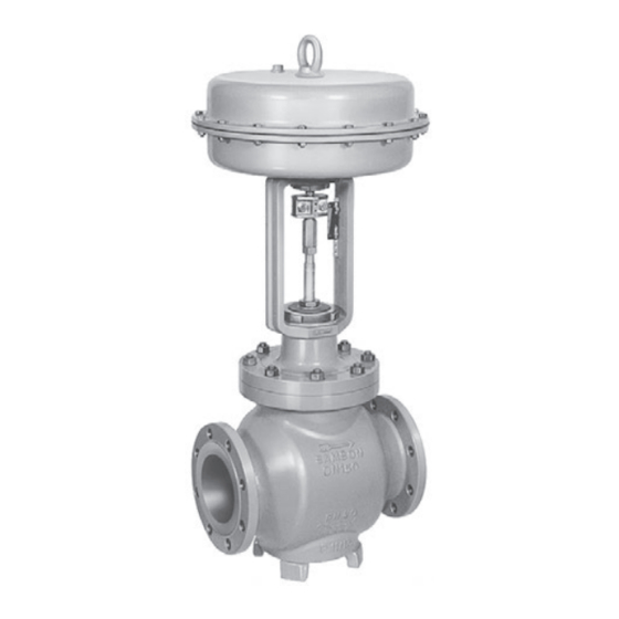
- Page 1 EB 8051 EN Translation of original instructions Type 3251 Valve with Type 3271 Actuator Type 3251 Valve · DIN version In combination with an actuator, e.g. a Type 3271 or Type 3277 Pneumatic Actuator Edition November 2022...
- Page 2 Note on these mounting and operating instructions These mounting and operating instructions assist you in mounting and operating the device safely. The instructions are binding for handling SAMSON devices. The images shown in these instructions are for illustration purposes only. The actual product may vary.
-
Page 3: Table Of Contents
Contents Safety instructions and measures ..............1-1 Notes on possible severe personal injury ............1-4 Notes on possible personal injury ..............1-5 Notes on possible property damage .............1-7 Notes on the use of an RFID tag ..............1-8 Warnings on the device ................1-8 Markings on the device ................2-1 Valve nameplate ..................2-1 Actuator nameplate ..................2-2 Material identification number ..............2-2... - Page 4 Removal ....................11-1 11.1 Removing the valve from the pipeline ............11-2 11.2 Removing the actuator from the valve ............11-2 Repairs ....................12-1 12.1 Returning devices to SAMSON ..............12-1 Disposal ....................13-1 Certificates ....................14-1 Annex......................15-1 15.1 Tightening torques, lubricants and tools ............15-1 15.2 Spare parts ....................15-1 15.3...
-
Page 5: Safety Instructions And Measures
SAMSON. SAMSON does not assume any liability for damage resulting from the failure to use the de- vice for its intended purpose or for damage caused by external forces or any other external factors. - Page 6 (see associated actuator documentation). When the valve is combined with a SAMSON Type 3271 or Type 3277 Pneumatic Actuator, the valve moves to a certain fail- safe position (see the 'Design and principle of operation' section) upon supply air or control signal failure.
- Page 7 Start-up and shutdown procedures fall within the scope of the operator's duties and, as such, are not part of these mounting and operating instructions. SAMSON is unable to make any statements about these procedures since the operative details (e.g. differential pressures and temperatures) vary in each individual case and are only known to the operator.
-
Page 8: Notes On Possible Severe Personal Injury
If a device contains a substance listed as a substance of very high concern on the candi- date list of the REACH regulation, this is indicated on the SAMSON delivery note. − Special mounting and operating instructions are available for the Type 3251 Globe Valve for molten salt service u EB 8052-1. -
Page 9: Notes On Possible Personal Injury
Safety instructions and measures 1.2 Notes on possible personal injury WARNING Risk of burn injuries due to hot or cold components and pipelines. Depending on the process medium, valve components and pipelines may get very hot or cold and cause burn injuries. Î... - Page 10 Risk of personal injury due to preloaded springs. Valves in combination with pneumatic actuators with preloaded springs are under ten- sion. These control valves with SAMSON pneumatic actuators can be identified by the long bolts protruding from the bottom of the actuator.
-
Page 11: Notes On Possible Property Damage
Î Observe the specified tightening torques (u AB 0100). Risk of valve damage due to the use of unsuitable tools. Certain tools are required to work on the valve. Î Only use tools approved by SAMSON (u AB 0100). EB 8051 EN... -
Page 12: Notes On The Use Of An Rfid Tag
The lubricants to be used depend on the valve material. Unsuitable lubricants may cor- rode and damage surfaces. Î Only use lubricants approved by SAMSON (u AB 0100). Risk of the process medium being contaminated through the use of unsuitable lubri- cants and/or contaminated tools and components. -
Page 13: Markings On The Device
DIN: D · ANSI/JIS: B appear on a valve nameplate. Only the in- Version: M: mixing valve · V: diverting valve scriptions relevant to the ordered Type 3251 Valve actually appear on the nameplate. EB 8051 EN... -
Page 14: Actuator Nameplate
15 Noise reduction: 1: flow divider (ST) 1 · 2: ST 2 · by SAMSON. The material number enables 3: ST 3 · 1/PSA: ST 1 standard and inte- you to view the device's technical data as grated in seat for PSA valve ·... -
Page 15: Optional Rfid Tag
Markings on the device Fig. 2-3: Label when an adjustable packing is installed 2.5 Optional RFID tag The RFID tag is located directly next to the nameplate on valves ordered with the RFID tag option. It contains the same data as in- cluded in the Data Matrix code on the elec- tronic nameplate. - Page 16 EB 8051 EN...
-
Page 17: Design And Principle Of Operation
See Fig. 3-1. Fail-safe action The Type 3251 Valve is a single-seated The fail-safe position of the control valve up- globe valve. This valve is preferably com- on air supply or control signal failure de- bined with a SAMSON Type 3271 or pends on the actuator used (see associated Type 3277 Pneumatic Actuator. - Page 18 Plug (with plug stem) Vent plug Travel indicator scale Threaded bushing Stem connector clamps (packing nut) Castellated nut Signal pressure Stem connector nut Actuator connection Fig. 3-1: Type 3251 Valve with Type 3271 Pneumatic Actuator (left) and Type 3277 Pneumatic Actuator (right) EB 8051 EN...
-
Page 19: Versions
Actuators Insulation In these instructions, the preferable combina- tion with a SAMSON Type 3271 or Control valves can be insulated to reduce Type 3277 Pneumatic Actuator is described. heat energy transfer. The pneumatic actuator (with or without... -
Page 20: Valve Accessories
SAMSON is unable to make general state- ments about noise emissions. The noise emis- Conformity sions depend on the valve version, plant fa- The Type 3251 Valve bears the CE, UKCA cilities and process medium. and EAC marks of conformity. Optional RFID tag... - Page 21 Dimensions and weights Table 3-1 to Table 3-4 provide an overview of the dimensions and weights of the standard version of Type 3251 Valve. The lengths and heights in the dimensional drawings are shown on page 3-7. Dimensions in mm · Weights in kg Table 3-1: Dimensions of Type 3251 Valve, up to DN 150 ·...
- Page 22 Design and principle of operation Table 3-2: Dimensions of Type 3251 Valve, DN 200 and larger Valve PN 10 to 40 1100 1250 Length L PN 63 to 160 1150 – 1) (flanges PN 250 and weld- PN 320 – ing ends) PN 400 PN 10 to 40 PN 63 to 160 –...
- Page 23 PN 63 to 160 30.5 Valve without PN 250 actuator PN 320 On request PN 400 Table 3-4: Weights for standard version of Type 3251 in DN 200 and larger Valve PN 16 to 40 1450 On request PN 63 to 160 1090 1480 2600 –...
- Page 24 Refer to the following data sheets for more dimensions and weights: u T 8051 for valves with bellows seal, insulating section or heating jacket The associated actuator documentation applies to actuators, e.g. SAMSON pneumatic actu- ators: u T 8310-1 for Type 3271 or Type 3277 Pneumatic Actuators up to 750 cm² actuator area u T 8310-2 for Type 3271 Actuator with 1000 cm²...
-
Page 25: Shipment And On-Site Transport
2. Check the shipment for transportation Î Stay clear of suspended or moving damage. Report any damage to loads. SAMSON and the forwarding agent Î Close off and secure the transport paths. (refer to delivery note). 3. Determine the weight and dimensions of... -
Page 26: Transporting The Valve
Risk of valve damage due to incorrectly at- tached slings. The control valve can be transported using The lifting eyelet/eyebolt on SAMSON lifting equipment (e.g. crane or forklift). actuators is only intended for mounting and Î Leave the control valve in its transport removing the actuator as well as lifting the container or on the pallet to transport it. -
Page 27: Lifting The Valve
Shipment and on-site transport 4.3.2 Lifting the valve − Protect the control valve against moisture and dirt. To install a large valve into the pipeline, use − The permissible transportation tempera- lifting equipment (e.g. crane or forklift) to lift ture of standard control valves is –20 to +65 °C/–4 to +149 °F. - Page 28 Shipment and on-site transport a) Version with flanges − Secure slings against slipping. − Make sure the slings can be removed 1. Attach one sling to each flange of the from the valve once it has been installed body and to the rigging equipment (e.g. into the pipeline.
-
Page 29: Storing The Valve
Î Observe the storage instructions. lowing valves upright with the actuator Î Avoid long storage times. on top: Î Contact SAMSON in case of different – ≥DN 100 for versions with pressure storage conditions or longer storage balancing times. - Page 30 Shipment and on-site transport EB 8051 EN...
-
Page 31: Installation
Plant operators must ensure that, after instal- temperatures below –10 °C lation of the device, the operating personnel Î Contact SAMSON if the mounting posi- can perform all necessary work safely and tion is not as specified above. easily access the device from the work posi- Support or suspension tion. -
Page 32: Preparation For Installation
Installation Vent plug Î Locate the vent plug on the opposite side to the work position of operating person- Vent plugs are screwed into the exhaust air nel. ports of pneumatic and electropneumatic de- vices. They ensure that any exhaust air that 5.2 Preparation for installation forms can be vented to the atmosphere (to avoid excess pressure in the device). - Page 33 Installation − The valve is clean. Note − The valve and all valve accessories (in- The plant operator is responsible for clean- cluding piping) are not damaged. ing the pipelines in the plant. − The valve data on the nameplate (type designation, valve size, material, pres- Î...
-
Page 34: Mounting The Device
(309) with unsuitable tools. their beveled part first (without using any Î Only use tools approved by SAMSON lubricant) into the recesses of the clamps (u AB 0100). (301) as far as they will go. Remove any excess material. - Page 35 Installation 9. Mount the actuator. See section 5.3.2. 10. Thread the stem (9) upwards until the head of the stem rests on the extended actuator stem. 11. Retract the actuator stem to relieve the stem (9). 12. Gradually tighten the screws (303) in a crisscross pattern.
- Page 36 Installation Plug stem Legend Yoke Screws Hanger Travel indicator scale Screws Castellated nut Warning label Ball bearing Fig. 5-1: Overview of yoke assembly with travel indicator scale in the standard version EB 8051 EN...
- Page 37 Installation Plug stem Legend Stem Lubricant Gleitmo 1763 V Clamps Screws Washers Sliding washers Fig. 5-2: Overview of anti-rotation fixture assembly in the standard version EB 8051 EN...
- Page 38 Installation b) Special version in valve sizes 8. Thread the stem (9) upwards until the head of the stem rests on the extended DN 50 to 100 actuator stem. See Fig. 5-3 and Fig. 5-4 9. Retract the actuator stem to relieve the stem (9).
- Page 39 Installation Legend Yoke Screws Hanger Plug stem Travel indicator scale Castellated nut Warning label Holder Screws Washers Fig. 5-3: Overview of yoke assembly with travel indicator scale in the special version EB 8051 EN...
- Page 40 Installation Plug stem Legend Stem Lubricant Gleitmo 1763 V Clamps Screws Washers Sliding washers Fig. 5-4: Overview of anti-rotation fixture assembly in the special version 5-10 EB 8051 EN...
- Page 41 Installation Table 5-4: Mounting dimensions for Types 3271 and 3277 Pneumatic Actuators · See Fig. 5-5 for dimensional drawing Trav- Actuator Actuator preloading Dimension when the valve is closed [mm] [cm²] [mm] [mm] DN 50 to 100/NPS 2 to 4 · Special version 3.75 –...
- Page 42 Installation Trav- Actuator Actuator preloading Dimension when the valve is closed [mm] [cm²] [mm] [mm] DN 200 to 250/NPS 8 to 10 up to seat bore 200 · Standard version 1000 1400-60 87.5 1400-120 2800 5600 DN 250/NPS 10, seat bore 250 and DN 300 to 500/NPS 12 to 20 · Standard version 1000 1400-60 1400-120...
- Page 43 Installation Ball bearings (standard version only) Fig. 5-5: Dimensional drawing with mounting dimensions for Types 3271 and 3277 Pneumatic Actuators EB 8051 EN 5-13...
-
Page 44: Mounting The Actuator Onto The Valve
Installation 5.3.2 Mounting the actuator Depending on the version, SAMSON control valves are either delivered with the actuator onto the valve already mounted on the valve or the valve and actuator are delivered separately. When WARNING delivered separately, the valve and actuator Risk of personal injury due to preloaded must be assembled together on site. - Page 45 Installation Versions with perforated plug Only one hole is located near the seal facing of perforated plugs with equal percentage characteristic. Depending on the valve size, the hole pattern varies and is partly unsym- Plug metrical. The process medium in the valve stem flows through the holes as soon as the plug is lifted out of the seat.
-
Page 46: Installing The Valve Into The Pipeline
Installation 4. Fix the travel indicator scale into place 4. Lift the valve using suitable lifting equip- by tightening the screws. ment to the site of installation (see the 'Lifting the valve' section). Observe the 5.3.3 Installing the valve into flow direction through the valve. - Page 47 Installation Î Depressurize all plant sections affected Î Before working on the control valve, dis- and the valve (including the actuator). connect and lock the pneumatic air sup- Release any stored energy. ply as well as the control signal. Î Drain the process medium from all the Î...
-
Page 48: Leak Test
Installation To test the valve functioning before start-up NOTICE or putting back the valve into operation, per- Impaired valve functioning due to increased form the following tests: friction as a result of the threaded bushing being tightened too far. 5.4.1 Leak test Î... -
Page 49: Travel Motion
Installation 5.4.2 Travel motion The movement of the actuator stem must be linear and smooth. Î Apply the maximum and minimum con- trol signals to check the end positions of the valve while observing the movement of the actuator stem. Î... - Page 50 5-20 EB 8051 EN...
-
Page 51: Start-Up
Start-up 6 Start-up Î Wear hearing protection when working near the valve. The work described in this section is only to be performed by personnel appropriately qualified to carry out such tasks. WARNING WARNING Crush hazard arising from actuator and WARNING plug stem moving. - Page 52 Start-up Before start-up or putting the valve back into service, make sure the following conditions are met: − The valve is properly installed into the pipeline (see the 'Installation' section). − The leak and function tests have been completed successfully (see 'Testing the installed valve' in the 'Installation' sec- tion).
-
Page 53: Operation
Operation 7 Operation Î Wear hearing protection when working near the valve. Immediately after completing start-up or put- ting the valve back into operation, the valve is ready for use. WARNING WARNING Crush hazard arising from actuator and WARNING plug stem moving. Risk of burn injuries due to hot or cold Î... -
Page 54: Normal Operation
Operation 7.1 Normal operation The handwheel of valves with actuators fitted with a handwheel must be in the neutral po- sition during normal operation. 7.2 Manual operation Valves with actuators fitted with a handwheel can be manually closed or opened in case of supply air failure. -
Page 55: Malfunctions
Malfunctions 8 Malfunctions Read hazard statements, warnings and caution notes in the 'Safety instructions and mea- sures' section. 8.1 Troubleshooting Malfunction Possible reasons Recommended action Actuator and plug stem Actuator is blocked. Check attachment. does not move on de- Remove the blockage. mand. -
Page 56: Emergency Action
Malfunctions Malfunction Possible reasons Recommended action The valve leaks to the Defective packing Replace packing (see the 'Servicing' section) or atmosphere (fugitive contact our after-sales service. emissions). Version with adjustable Adjust the packing (see information under 'Adjust- packing : packing not ing the packing' in the 'Testing the installed valve' 2) tightened correctly... -
Page 57: Servicing
Servicing 9 Servicing Î Allow components and pipelines to cool down or warm up to the ambient tem- The work described in this section is only to perature. be performed by personnel appropriately Î Wear protective clothing and safety qualified to carry out such tasks. gloves. - Page 58 Risk of valve damage due to the use of WARNING unsuitable tools. Risk of personal injury due to preloaded Î Only use tools approved by SAMSON springs. (u AB 0100). Actuators with preloaded springs are under tension. They can be identified by the long...
-
Page 59: Periodic Testing
Servicing 9.1 Periodic testing Note The control valve was checked by SAMSON Depending on the operating conditions, before it left the factory. check the valve at certain intervals to prevent − Certain test results certified by SAMSON possible failure before it can occur. Plant op-... - Page 60 Servicing Inspection and testing Action to be taken in the event of a negative result: Check the test connection and bellows Put the control valve out of operation (see the seal (if used) for external leakage. 'Decommissioning' section). To repair the bellows seal, WARNING! Risk of personal injury due contact our after-sales service (see the 'Repairs' section).
- Page 61 5 Plug (with plug stem) 17 Body gasket 7 Guide bushing 21 Insulating section 8 Threaded bushing 92 Castellated nut (packing nut) Fig. 9-1: Standard version of Type 3251 with Type 3271 Actuator (left) and Type 3251 in version with insulating section (right) EB 8051 EN...
-
Page 62: Preparing The Valve For Service Work
Servicing 9.2 Preparing the valve for pressure must be removed and the air supply disconnected again and locked. service work WARNING Risk of personal injury due to incorrect re- We recommend removing the valve from the moval of the anti-rotation fixture under ten- pipeline before performing any service work sion. -
Page 63: Service Work
Servicing 9.4 Service work Version with V-port plug: place the flange (2) onto the valve body, making Î Before performing any service work, sure that the largest V-shaped port of the preparations must be made to the control V-port plug faces towards the valve out- valve (see section 9.2). -
Page 64: Replacing The Packing
Servicing a) Standard version port of the V-port plug faces towards the valve outlet. Version with perforated plug: place the Standard packing (PTFE) insulating section (21) onto the valve 1. Unscrew the castellated nut (92) and lift body, making sure that the hole of the the yoke (3) off the flange (2). - Page 65 Servicing 8 Threaded bushing 11 Spring 12 Washer 16 Packing ring 19 Spacer Fig. 9-2: Standard packing: DN 15 to 40 (left) and DN 50 to 100 (right) See relevant information under 'Mount- 15. Place yoke (3) on the flange (2) and fas- ing the actuator onto the valve' in the 'In- ten using the castellated nut (92).
- Page 66 Servicing Insert the wire of the red spacer ring 5. Proceed as described in ‘Standard pack- (15.1) into the groove of the retaining ing (PTFE)’, steps 13 to 16. ring. Slide the retaining ring over the plug stem. 4. Insert the red spacer ring (15.1) between the threaded bushing (8) and retaining ring.
- Page 67 Servicing b) Version with insulating body, making sure that the hole of the plug that releases the flow first faces to- section ward the valve outlet. See relevant information under 'Mount- Standard packing (PTFE) ing the actuator onto the valve' in the 'In- 1.
-
Page 68: Replacing The Seat And Plug
Servicing 4. Insert the red spacer ring (15.1) between the threaded bushing (8) and retaining When replacing the seat and plug, we also ring. See Fig. 9-3. recommend replacing the packing (see sec- 5. Proceed as described in ‘Standard pack- tion 9.4.2). ing (PTFE)’, steps 13 to 16. - Page 69 Servicing b) Version with insulating We recommend replacing the packing as well. See section 9.4.2. section 14. Slide the new plug with plug stem (5) in- to the flange (2). 1. Unscrew the castellated nut (92) and lift the yoke (3) off the insulating section 15.
-
Page 70: Ordering Spare Parts And Operating Supplies
Version with V-port plug: place the insu- Contact your nearest SAMSON subsidiary lating section (21) onto the valve body, or SAMSON's After-sales Service for infor- making sure that the largest V-shaped mation on spare parts, lubricants and tools. port of the V-port plug faces towards the Spare parts valve outlet. -
Page 71: Decommissioning
Decommissioning 10 Decommissioning WARNING The work described in this section is only to Risk of personal injury due to pressurized be performed by personnel appropriately components and process medium being qualified to carry out such tasks. discharged. Î Do not loosen the screw of the test con- nection while the valve is pressurized. - Page 72 Decommissioning (e.g. due to seizing up after remaining in 3. Disconnect and lock the pneumatic air the same position for a long time), re- supply to depressurize the actuator. lease any stored energy in the actuator 4. Release any stored energy. (e.g.
-
Page 73: Removal
Removal 11 Removal WARNING WARNING The work described in this section is only to Risk of personal injury due to residual be performed by personnel appropriately process medium in the valve. qualified to carry out such tasks. While working on the valve, residual me- dium can flow out of the valve and, depend- ing on its properties, cause personal injury, WARNING... -
Page 74: Removing The Valve From The Pipeline
Removal springs is transmitted to the actuator stem 3. Remove the valve from the pipeline (see and the stem (9). the 'Shipment and on-site transport' sec- Î First remove the actuator from the valve tion). or ensure it cannot transmit any forces to 11.2 Removing the actuator the actuator stem before removing the anti-rotation fixture on the plug stem. -
Page 75: Repairs
Î Do not perform any repair work on your outside of your shipment so that the own. documents are clearly visible. Î Contact SAMSON's After-sales Service 3. Send the shipment to the address given for repair work. on the RMA. - Page 76 12-2 EB 8051 EN...
-
Page 77: Disposal
Disposal 13 Disposal SAMSON is a producer registered at the following European institution u https://www.ewrn.org/national- registers/national-registers. WEEE reg. no.: DE 62194439/ FR 02566 Î Observe local, national and internation- al refuse regulations. Î Do not dispose of components, lubricants and hazardous substances together with your household waste. - Page 78 13-2 EB 8051 EN...
-
Page 79: Certificates
Country of origin: France, see page 14-3 to 14-6 − Declaration of conformity in compliance with Machinery Directive 2006/42/EC for Types 3251-1 and 3251-7 Control Valves on page 14-7 − Declaration of incorporation in compli- ance with Machinery Directive 2006/42/EC for the Type 3251 Valve with other actuators other than Types 3271 and 3277 Actuators on... - Page 80 14-2 EB 8051 EN...
- Page 81 Module H / Modul H, N°/ Nr CE-0062-PED-H-SAM 001-20-FRA-rev-A 2022-05 Par la présente, SAMSON REGULATION SAS déclare sous sa seule responsabilité pour les produits suivants : For the following products, SAMSON REGULATION SAS hereby declares under its sole responsibility: Appareils / Exécution /...
- Page 82 The manufacturer’s quality management system is monitored by the following notified body: Bureau Veritas Services SAS N°/Nr 0062, 8 Cours du Triangle, 92800 PUTEAUX - LA DEFENSE Fabricant / manufacturer : Samson Régulation SAS, 1, rue Jean Corona, FR-69120 VAULX-EN-VELIN Vaulx-en-Velin, le 23/05/22 Bruno Soulas Joséphine Signoles-Fontaine...
- Page 83 DC014 Module A / Modul A 2022-05 Par la présente, SAMSON REGULATION SAS déclare sous sa seule responsabilité pour les produits suivants : For the following products, SAMSON REGULATION SAS hereby declares under its sole responsibility: Appareils / Exécution / Matériel du corps / body...
- Page 84 Modul A Normes techniques appliquées / Technical standards applied : DIN EN 12516-2, DIN EN 12516-3, ASME B16.34, DIN-EN 60534-4, DIN-EN 1092-1 Fabricant / manufacturer : Samson Régulation SAS, 1, rue Jean Corona, FR-69120 VAULX-EN-VELIN Vaulx-en-Velin, le 23/05/22 Bruno Soulas Joséphine Signoles-Fontaine...
- Page 85 EB 8051 EN 14-7...
- Page 86 14-8 EB 8051 EN...
- Page 87 EB 8051 EN 14-9...
- Page 88 Machinery components can be mounted onto the above specified final ma- chinery if they comply with the specifications and properties defined by SAMSON Manual H 02 “Ap- propriate Machinery Components for SAMSON Pneumatic Control Valves with a Declaration of Con- formity of Final Machinery”.
- Page 89 Peter Scheermesser Director Director Product Management Product Life Cycle Management and ETO Development for Valves and Actuators Revision 00 Classification: Public · SAMSON AKTIENGESELLSCHAFT · Weismuellerstrasse 3 · 60314 Frankfurt am Main, Germany Page 1 of 1 EB 8051 EN 14-11...
- Page 90 14-12 EB 8051 EN...
-
Page 91: Annex
Annex 15 Annex 15.1 Tightening torques, lubricants and tools u AB 0100 for tools, tightening torques and lubricants 15.2 Spare parts 1 Body 29 Plug for version with 63 Ring 2) bellows seal 2 Flange 64 Gasket 2) 30 Retaining washers 3 Yoke 65 Gasket 2) 32 Bolt... - Page 92 80 81 80 81 83 84 42/43 (DN 15...150) (NPS ½...6) 13 91 102/103 15-2 EB 8051 EN...
-
Page 93: After-Sales Service
Addresses of SAMSON AG and its subsid- Importer iaries SAMSON Controls Ltd The addresses of SAMSON AG, its subsid- Perrywood Business Park iaries, representatives and service facilities Honeycrock Lane worldwide can be found on our website Redhill, Surry RH1 5JQ (www.samsongroup.com) or in all SAMSON Phone: +44 1737 766391... - Page 94 15-4 EB 8051 EN...
- Page 96 EB 8051 EN SAMSON AKTIENGESELLSCHAFT Weismüllerstraße 3 · 60314 Frankfurt am Main, Germany Phone: +49 69 4009-0 · Fax: +49 69 4009-1507 samson@samsongroup.com · www.samsongroup.com...
Need help?
Do you have a question about the 3251 and is the answer not in the manual?
Questions and answers