Samson 3251 Mounting And Operating Instructions
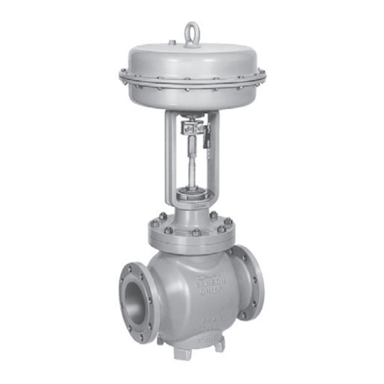
Valve for molten salt service - ansi version in combination with an actuator, e.g. a samson type 3271 or type 3277 pneumatic actuator
Hide thumbs
Also See for 3251:
- Mounting and operating instructions (108 pages) ,
- Mounting and operating instructions (96 pages) ,
- Mounting and operating instructions (60 pages)

Related Manuals for Samson 3251


Summary of Contents for Samson 3251
- Page 1 EB 8052-1 EN Translation of original instructions Type 3251 Valve for molten salt service · ANSI version In combination with an actuator, e.g. a SAMSON Type 3271 or Type 3277 Pneumatic Actuator Edition August 2016...
- Page 2 Î For the safe and proper use of these instructions, read them carefully and keep them for later reference. Î If you have any questions about these instructions, contact SAMSON‘s After-sales Service Department (aftersalesservice@samson.de). The mounting and operating instructions for the devices are included in the scope of delivery.
-
Page 3: Table Of Contents
Contents Safety instructions and measures ..............5 Notes on possible severe personal injury ............8 Notes on possible personal injury ..............9 Notes on possible property damage ..............10 Markings on the control valve ..............12 Valve nameplate ..................12 Actuator nameplate ..................13 Material number ..................13 Design and principle of operation ..............14 Fail-safe positions ..................14 Versions ......................16... - Page 4 Contents Operation ....................38 Working in manual mode ................39 Servicing.....................40 Inspection intervals ..................41 Replacing the gasket ..................43 7.2.1 Standard version..................43 7.2.2 Version with bellows seal ................43 Replacing the packing ..................45 Replacing the seat and plug ................47 Cleaning the pipelines ..................48 Preparation for return shipment ..............49 Ordering spare parts and operating supplies ..........49 Malfunctions ....................50 Troubleshooting ...................50...
-
Page 5: Safety Instructions And Measures
In case operators intend to use the control valve in other applications or conditions than specified, SAMSON must be contacted. SAMSON does not assume any liability for damage resulting from the failure to use the valve for its intended purpose or for damage caused by external forces or any other external factors. - Page 6 Î Check with the plant operator for details on further protective equipment. Revisions and other modifications Revisions, conversions or other modifications to the product are not authorized by SAMSON. They are performed at the user's own risk and may lead to safety hazards, for example. Fur- thermore, the product may no longer meet the requirements for its intended use.
- Page 7 The following documents apply in addition to these mounting and operating instructions: − Mounting and operating instructions for mounted actuator, e.g. u EB 8310-X for SAMSON Type 3271 and Type 3277 Actuators − Mounting and operating instructions for mounted valve accessories (temperature sensor, positioner, solenoid valve, etc.) −...
-
Page 8: Notes On Possible Severe Personal Injury
Safety instructions and measures 1.1 Notes on possible severe personal injury DANGER Risk of bursting in pressure equipment. Control valves and pipelines are pressure equipment. Improper opening can lead to valve components bursting. Î Before starting any work on the control valve, depressurize all plant sections concerned as well as the valve. -
Page 9: Notes On Possible Personal Injury
Risk of personal injury due to preloaded springs. Valves in combination with pneumatic actuators with preloaded springs are under ten- sion. These control valves with SAMSON pneumatic actuators can be identified by the long bolts protruding from the bottom of the actuator. -
Page 10: Notes On Possible Property Damage
Safety instructions and measures WARNING Risk of personal injury due to residual process medium in the valve. While working on the valve, residual process medium can escape and may lead to per- sonal injury, e.g. burns. Î If possible, drain the process medium from all the plant sections concerned and from the valve. - Page 11 Risk of valve damage due to the use of unsuitable lubricants. The lubricants to be used depend on the valve material. Unsuitable lubricants may cor- rode and damage the valve surface. Î Only use lubricants approved by SAMSON (see parts list). EB 8052-1 EN...
-
Page 12: Markings On The Control Valve
Markings on the control valve 2 Markings on the control valve 2.1 Valve nameplate SAMSON Fig. 1: Valve nameplate 1…5 14 15 16 17 1…5 PED (Pressure Equipment Directive), "Art. 4, Abs. 3" ID of the notified body, fluid group, and category... -
Page 13: Actuator Nameplate
Markings on the control valve The nameplate (80) is affixed to the yoke of the valve (see Fig. 2). Fig. 2: Nameplate position 2.2 Actuator nameplate See associated actuator documentation. 2.3 Material number The seat and plug of the valves have an arti- cle number written on them. -
Page 14: Design And Principle Of Operation
The medium flows through the valve in the The single-seated Type 3251 Globe Valve is direction indicated by the arrow. A rise in preferably combined with a SAMSON signal pressure causes the force acting on Type 3271 or Type 3277 Pneumatic Actuator... - Page 15 Design and principle of operation Connection for temperature sensor Fig. 3: Type 3251 Valve for molten salt service: with welding ends, bellows seal, and Type 3271 Pneumatic Actuator (left) · Standard version with flanges (right) EB 8052-1 EN...
-
Page 16: Versions
Î Observe the maximum permissible actu- ator force. Table 1: Technical data Type 3251 Valve for molten salt service Material Body A351 CF8C Process medium Molten salt... -
Page 17: Technical Data
Table 1. Note More information is available in Data Sheet u T 8052. Noise emission SAMSON is unable to make general state- ments about noise emission as it depends on the valve version, plant facilities, and pro- cess medium. WARNING Risk of hearing loss or deafness due to loud noise. - Page 18 Table 2 to Table 5 provide a summary of the dimensions and weights of the standard version of Type 3251 Valve. Table 6 to Table 9 provide a summary of the dimensions and weights of the Type 3251 Valve with bellows seal. The lengths and heights are defined in the dimension diagrams on p. 19 and are based on a valve combined with a SAMSON Type 3271 or...
- Page 19 600 with foot) 2.76 3.05 3.94 4.33 4.72 7.09 9.25 Class 900 Dimensional drawings Type 3251 up to NPS 3 without Type 3251 in NPS 4 and larger Type 3251 Valve with bellows foot with foot seal and welding ends EB 8052-1 EN...
- Page 20 Design and principle of operation Table 3: Dimensions of Type 3251 Valve, NPS 8 and larger Valve – 21.38 26.50 29.00 35.00 40.00 Class 150 On request 1016 22.38 27.88 30.50 36.50 41.62 Length L Class 300 On request 1057 (flanges RF and welding 24.00...
- Page 21 Class 900 On request NPS 10, Class 150 to 300: 17.40” or 442 mm NPS 10, Class 600 to 900: 20.43” or 519 mm H8 = 25.59“ or 650 mm with 250 mm seat bore Table 4: Weights for standard version of Type 3251, up to NPS 6 ½ 1½ Valve Class 150...
- Page 22 Design and principle of operation Table 6: Dimensions of Type 3251 Valve with metal bellows, up to NPS 6 ½ 1½ Valve size Travel 14.25 14.25 14.72 23.94 24.13 24.13 27.72 Class 150 0.59 to 2.36” Height 15 to 60 mm 14.25 14.25 14.72 23.94...
- Page 23 Design and principle of operation Table 9: Weights of Type 3251 Valve with metal bellows, NPS 8 and larger Valve size – 1146 2150 2227 Class 150 1010 1146 2150 2227 Class 300 Valve 1010 without On request 1312 2740 2734 actuator Class 600...
-
Page 24: Measures For Preparation
2. Check the shipment for transportation WARNING damage. Report any damage to Risk of lifting equipment tipping and risk of SAMSON and the forwarding agent (re- damage to lifting accessories due to exceed- fer to delivery note). ing the rated lifting capacity. -
Page 25: Transporting
Risk of valve damage due to incorrectly at- damage immediately. tached slings. − Protect the control valve against moisture The welded‑on lifting eyelet on SAMSON and dirt. actuators is only intended for mounting and − The permissible transportation tempera- removing the actuator as well as lifting the ture of standard control valves is –20 to... - Page 26 Measures for preparation equipment (hook, shackle etc.) does not bear any load when lifting valves larger than NPS 6. The sling only protects the control valve from tilting while being lift- ed. Before lifting the control valve, tight- en the sling. Fig. 4: Lifting points on the control valve: with welding ends (left) ·...
- Page 27 Measures for preparation Version with flanges Version with welding ends 1. Attach one sling to each flange of the 1. Attach one sling to each welding end of body and to the rigging equipment (e.g. the body and to the rigging equipment hook) of the crane or forklift (see Fig. 4).
-
Page 28: Storage
Special storage instructions for elastomers packing before stroking the valve. Elastomer, e.g. actuator diaphragm − Contact SAMSON in case of different stor- age conditions or long storage periods. − To keep elastomers in shape and to pre- vent cracking, do not bend them or hang them up. -
Page 29: Preparation For Installation
Measures for preparation 4.4 Preparation for installation Proceed as follows: Î Flush the pipelines. Note The plant operator is responsible for clean- ing the pipelines in the plant. Î Check the valve to make sure it is clean. Î Check the valve for damage. Î... -
Page 30: Mounting And Start-Up
Mounting and start-up 5 Mounting and start-up 5.1 Mounting the actuator onto the valve SAMSON valves are delivered ready for use. In special cases, the valve and actuator Proceed as described in the actuator docu- are delivered separately and must be assem- mentation if the valve and actuator have not bled on site. -
Page 31: Installing The Valve Into The Pipeline
In the following versions, the valve must be perform service and repair work on installed with the actuator on top: them. − Valves in NPS 4 and larger Î Contact SAMSON if the mounting posi- tion is not as specified here. EB 8052-1 EN... - Page 32 Mounting and start-up Table 10: Inlet and outlet lengths Flow rate Inlet length Outlet length a x NPS b x NPS State of process Valve conditions Inlet length a Outlet length b medium Ma ≤ 0.3 0.3 ≤ Ma ≤ 0.7 Free of cavitation/w < 10 m/s Cavitation producing noise/w ≤ 3 m/s Cavitation producing Liquid noise/3 < w < 5 m/s...
-
Page 33: Additional Fittings
Mounting and start-up Î Locate the vent plug on the opposite side Heating jacket to the workplace of operating personnel. The control valve can be fitted with a heating Î On mounting valve accessories, make jacket on request. sure that they can be operated from the Bypass and shut-off valves workplace of the operating personnel. -
Page 34: Installing The Control Valve
Mounting and start-up 5.2.3 Installing the control Version with welding ends valve 1. Proceed as described for Version with flanges (steps 1 to 3). Version with flanges 2. Completely retract the actuator stem to 1. Close the shut-off valve in the pipeline protect the plug from sparks during weld- while the valve is being installed. -
Page 35: Determining The Temperature Limits
Minimum temperature The minimum temperature depends on the Note melting point of the salt used. In turn, the SAMSON can calculate the required heating melting point depends on the composition of power on request for a specific application. the salt. -
Page 36: Quick Check
Mounting and start-up 5.4 Quick check Adjustable packing SAMSON valves are delivered ready for use. To test the valve's ability to function, the A label on the bonnet (2) indicates that an following quick checks can be performed: adjustable packing is installed. - Page 37 Form MS packing. See section 7.3. Note The plant operator is responsible for per- forming the pressure test. SAMSON's Af- ter‑sales Service department can support you to plan and perform a pressure test for your plant. EB 8052-1 EN...
-
Page 38: Operation
Operation 6 Operation WARNING Immediately after completing mounting and Risk of poisoning from molten salt vapors. start-up (see section 5), the valve is ready for Molten salt in the liquefied state produces use. vapors that are toxic. − Do not inhale molten salt vapors. −... -
Page 39: Working In Manual Mode
Operation − Only stroke the valve with bellows seal when the process medium is in the lique- fied state. NOTICE Operation disturbed by a blocked actuator or plug stem. Do not impede the movement of the actuator or plug stem by inserting objects into their path. -
Page 40: Servicing
Servicing 7 Servicing − Do not touch molten salt. − Wear protective clothing and safety gloves We recommend removing the valve from the when handling molten salt. pipeline for service or repair work (see sec- tion 9.2). WARNING DANGER Fire risk due to molten salt. Risk of bursting in pressure equipment. -
Page 41: Inspection Intervals
Servicing − Certain test results (seat leakage and leak NOTICE test) certified by SAMSON lose their validi- Risk of valve damage due to incorrect servic- ty when the valve body or actuator hous- ing or repair. ing is opened. Service and repair work must only be −... - Page 42 Contact SAMSON's Af- At least every two years Replace the packing ter-sales Service depart- ment. SAMSON's After‑sales Service department can support you to draw up an inspection plan for your plant. EB 8052-1 EN...
-
Page 43: Replacing The Gasket
Version with bellows − The valve does not have a flow divider. seal To replace the gasket in other valve versions, contact SAMSON's After‑sales Service de- 1. Remove the actuator from the valve. See partment. associated actuator documentation. 2. Undo the body nuts (14) gradually in a 7.2.1... - Page 44 Servicing Connection for temperature sensor Fig. 5: Type 3251 Valve for molten salt service: with welding ends, bellows seal, and Type 3271 Pneumatic Actuator (left) · Standard version with flanges (right) EB 8052-1 EN...
-
Page 45: Replacing The Packing
(2) onto the valve body, making sure To replace the packing in other valve ver- that the largest V-shaped port of the sions, contact SAMSON's After‑sales Service V-port plug faces toward the valve outlet. department. See section 5.1. Body... - Page 46 Servicing 12. Carefully slide each packing ring (16) 13. Press the plug (5) firmly into the seat (4), separately into the packing chamber us- while fastening down the bonnet (2) with ing a suitable tool. See Fig. 6. Make sure the body nuts (14). Tighten the nuts that the packing ring is properly seated gradually in a criss-cross pattern.
-
Page 47: Replacing The Seat And Plug
11. Unscrew the seat (4) using a suitable To replace seat and plug in other valve ver- tool. sions, contact SAMSON's After‑sales Service 12. Apply a suitable lubricant to the thread department. and the sealing cone of the new seat. -
Page 48: Cleaning The Pipelines
Servicing 7.5 Cleaning the pipelines 18. Screw in the threaded bushing (8) and tighten it. Observe tightening torques. Make sure the following conditions are met 19. Place yoke (3) on the bonnet (2) and fas- when the valve is installed: ten tight using the castellated nut (92). -
Page 49: Preparation For Return Shipment
Defective valves can be returned to Contact your nearest SAMSON subsidiary SAMSON for repair. or the SAMSON After-sales Service depart- ment for information on spare parts, lubri- Proceed as follows to return valves to cants, and tools. SAMSON: Spare parts 1. -
Page 50: Malfunctions
Check the signal pressure line for leakage. Actuator or plug stem does not Packing tightened too far. Replace packing (see sec- move smoothly. tion 7.3) or contact SAMSON's After-sales Service department. The medium has crystallize in the Replace packing (see sec- packing. tion 7.3) or contact SAMSON's After-sales Service department. -
Page 51: Emergency Action
SAMSON's After-sales Service department). Note Contact SAMSON's After‑sales Service department for malfunctions not listed in the table. 8.2 Emergency action blocked. The bellows seal is damaged as a result. Upon supply air or control signal failure, the −... -
Page 52: Decommissioning And Disassembly
Decommissioning and disassembly 9 Decommissioning and − Wear protective clothing and safety gloves when handling molten salt. disassembly DANGER WARNING Risk of bursting in pressure equipment. Fire risk due to molten salt. Control valves and pipelines are pressure Individual elements in molten salt (both in equipment. -
Page 53: Decommissioning
Decommissioning and disassembly NOTICE NOTICE Risk of damage to the valve and pipelines Risk of damage to the valve and pipelines due to the process medium crystallizing. due to the process medium crystallizing. The molten salt crystallizes when its tempera- The crystallized medium can collect in the ture falls below the salt's melting point. -
Page 54: Removing The Actuator From The Valve
3. Remove the valve from the pipeline (see Addresses of SAMSON AG and its subsid- section 4.2). iaries The addresses of SAMSON AG, its subsid- 9.3 Removing the actuator iaries, representatives, and service facilities from the valve worldwide can be found on the SAMSON website, in all SAMSON product catalogs or See associated actuator documentation. - Page 55 Modul/Module H / N° CE-PED-H-SAM 001-13-DEU SAMSON erklärt in alleiniger Verantwortung für folgende Produkte/explaines in sole resposibility for the following products: Geräte/Devices Bauart/Series Typ/Type Ausführung/Version DIN, Gehäuse GG/Cast iron-Body ab/from DN150, Gehäuse GGG/Sph. gr. iron-Body ab/from DN100, Fluide/Fluids G2, L1, L2...
-
Page 56: Spare Parts
Appendix 10.3 Spare parts Body Nameplate Bonnet Grooved pin Yoke Screw Seat Hanger Plug Travel indicator scale Bellows nut Screw Guide bushing Protective caps Threaded bushing (packing nut) Stem connector nut Expansion sleeve Lock nut Expansion sleeve Washer Bellows bonnet 12.1 Washer Version with flow divider... - Page 57 80 81 80 81 83 42/43 12.1 12.1 EB 8052-1 EN...
- Page 58 EB 8052-1 EN...
- Page 59 EB 8052-1 EN...
- Page 60 EB 8052-1 EN SAMSON AKTIENGESELLSCHAFT Weismüllerstraße 3 · 60314 Frankfurt am Main, Germany Phone: +49 69 4009-0 · Fax: +49 69 4009-1507 samson@samson.de · www.samson.de...
Need help?
Do you have a question about the 3251 and is the answer not in the manual?
Questions and answers