Pyronix STERLING 10 Installation Instructions Manual
Led keypad
Hide thumbs
Also See for STERLING 10:
- Installation manual (48 pages) ,
- User manual (24 pages) ,
- Installation instructions (2 pages)
Table of Contents
Advertisement
Advertisement
Table of Contents

Subscribe to Our Youtube Channel
Related Manuals for Pyronix STERLING 10


Summary of Contents for Pyronix STERLING 10
-
Page 1: System Option
STERLING INSTALLATION INSTRUCTIONS LED KEYPAD STERLING INSTALLER DETAI LS: ® TELEPHONE: Pyronix Ltd. October 2001 This product is approved for use in the Residential, Commercial and Light Industrial Environment. RINS136 Issue 9... -
Page 2: Programmable Output
This product is sold subject to our standard warranty conditions and is warranted against defects in workmanship for a period of 2 years. In the interest of continuing improvement of quality, customer care and design, Pyronix reserve the right to amend specifications without giving prior notice. -
Page 3: Table Of Contents
Contents INTRODUCTION SAFETY ACCESS LEVELS OPERATING MODES ZONES Programmable Zones Dedicated Zones CONTROLS AND FUNCTIONS INSTALLATION Panel Assembly (Steel Version) Panel Assembly (Plastic Version) POWER CONNECTIONS Mains Connections Battery Connection Bell and Strobe (Transistor Version) 8.3.1 Bell and Strobe (Relay Version) Remote Keypad ‘RKP’... -
Page 4: System Option
TECHNICAL SPECIFICATION 12.1 Power supply 12.2 Control PCB 12.3 Mechanical 12.4 Environmental 12.5 Cleaning ENGINEER QUICK REFERENCE PROGRAMMING SECTION EXAMPLE WIRING SCHEMATICS 14.1 EXAMPLE WIRING SCHEMATICS RELAY VERSION PROGRAMMED OPTIONS STERLING 10 SERVICE HISTORY 8 ZONE PROGRAMMING LABEL Page 4... -
Page 5: Introduction
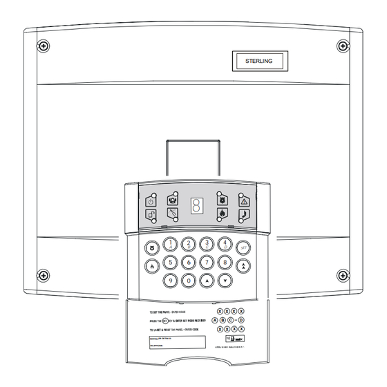
INTRODUCTION The Sterling 10 intruder alarm control panel is based around a micro-controller with 8 fully programmable zones. Operated via a single Remote keypad situated at a convenient point around the premises. Up to four additional keypads may be installed. Each keypad has an arrangement of 8 LEDs to show the status of the system, and a 7 segment display to show programming data and events held in the event-log memory. -
Page 6: Safety
SAFETY 1. The mains electrical installation should be carried out in accordance with National and local regulations by a technically competent person. 2. Always remove / isolate the mains supply before carrying out servicing of the panel. 3. Connect the unit to a single pole fused spur. If the neutral cannot be identified use a double pole disconnect version. - Page 7 Rins136 Issue 9 Page 7...
-
Page 8: Access Levels
ACCESS LEVELS Limited User Level Enables: a. Panel Setting and Unsetting with a unique pass code. b. Enabling and disabling of the door chime facility. c. Event log viewing. Master User Level Enables: a. All Limited User facilities. b. Alteration of both Limited and Master User codes. c. -
Page 9: Operating Modes
OPERATING MODES Unset This is when the panel is in day mode and is indicated by a green ‘Day’ LED on the front of the RKP. Fire, Personal Attack and Tamper inputs remain permanently active. When the panel is Set, an activation of any Access, Immediate or 24 hour zone will cause an alarm condition. -
Page 10: Controls And Functions
Only entry/exit zones configured in Set A, will generate a chime. Event Log The Sterling 10 control panel incorporates a memory log of the last 100 alarm events and is accessible to both Users and the Engineer. It will record Fire, Intruder, Personal Attack and Tamper alarms and also show if any of the 8 alarm zones have been triggered or omitted. - Page 11 NOTE: Only Programmable Output 1 has this option. Programmable Output connections are marked on the PCB as PGM Outputs 1 and 2. Code Tamper: During set mode, entry of an invalid code will operate the Code Tamper. After sixteen incorrect key pushes a full alarm condition will be generated. This will be logged as a Tamper in the events log.
- Page 12 All Resets: After any alarm condition (P.A. Fire or zone) an engineer code or anti code must be entered. System option 1 must be configured for engineer only system reset or System Option 4 anti code reset. System Option 3. Alarm Digi Active High: This will switch from 0 to 12V at the alarm digi com output when the alarm is activated.
-
Page 13: Installation
INSTALLATION Before beginning any installation work read through this section carefully. Plan out the various areas and degrees of protection required from each zone. It is important to decide which type each zone should be if part sets are to be used. Work out the cable routes avoiding mains cabling and consider the chosen position for the control panel. -
Page 14: Panel Assembly (Steel Version)
Panel Assembly (Steel Version) Support Posts 98037 Take off the front cover and remove the components. Push in the PCB support posts from the rear of the panel as shown. Assemble the tamper switch from the kit of parts as indicated. NOTE: When installing the panel cover the long screw should be used in the top hole, this will enable the tamper switch to be operated correctly. -
Page 15: Panel Assembly (Plastic Version)
Panel Assembly (Plastic Version) The Sterling 10 plastic case is packaged with the transformer, speaker and tamper switch in place. The speaker cover, tamper switch pin and cable knock out should be removed from the panel prior to affixing to the wall. - Page 16 Remove the tamper pin and insert into the tamper pin hole from the rear of the panel. Remove the cable knock-outs as required. Fix the control panel to the wall using the screws and fitting supplied. Carefully place the PCB onto the supports and push into place.
-
Page 17: Power Connections
L – live, E – earth and N – neutral. 8.2 Battery Connection In order for the Sterling 10 to operate if the mains power is cut a battery backup is required. Refer to 8.13 for battery specifications. Connect the battery to the terminals marked +BAT- on the PCB. -
Page 18: Remote Keypad 'Rkp' Connections
Remote Keypad ‘RKP’ Connections If more than one keypad is to be used, additional keypads can be wired in either daisy chain or star configuration. 8.4.1 Wiring for single Remote Keypad 8.4.2 Wiring for multiple Remote Keypads (daisy chain) 8.4.3 Wiring for multiple Remote Keypads (star configuration) PANEL RKP1... -
Page 19: Detection Zones
Auxiliary and Tamper The Sterling 10 has a dedicated tamper. All tamper circuits must be returned to this terminal and wired in series. 8.7 Personal Attack PA The Sterling 10 has a dedicated PA. All PA circuits must be returned to this terminal and wired in series. -
Page 20: Digital Communicators
8.10 Digital Communicators The Digital Communicators can be programmed to switch between 0 to 12V or 12 to 0V except the line fail which is factory set for input to 0V. 8.11 Programmable Outputs There are two programmable Outputs which are switched negative (-) to positive (+) or positive (+) to negative (-) depending upon which System Option is programmed. -
Page 21: Battery Capacity
Battery Capacity It is recommended that the rechargeable battery used with the Sterling 10 control panel should be capable of powering the alarm system for a minimum of 8 hours, and that this time period should include 20 minutes of bell/strobe operation. -
Page 22: Programming
PROGRAMMING The Sterling 10 may be programmed to suit a wide variety of installations. The following pages show the programmed options available and how to change them. Once the engineer mode has been entered, each section may be changed in any order. -
Page 23: Setting The Panel When Mains Fails
Incorrect entry gives an audible error tone and correct entry gives three bleeps. The alarm bell cut off time for the Sterling 10 is factory set to 20 minutes. Setting Entry Time To set the required Entry time. -
Page 24: Changing The Engineer Code
Incorrect entry gives an audible error tone and correct entry gives three bleeps. Communication Delay is factory set at zero seconds. 9.11 Changing the Engineer Code Enter Then the old Engineer Code (Factory Set at 9999) -this gives an audible acceptance tone. Then the new Engineer Code - gives an audible acceptance tone Then... -
Page 25: Programmable Re-Sets
9.12.6 System Option 4. Enter followed by to toggle RKP LEDs Keypad LED LED ON LED OFF Alarm Abort digi active high Abort digi active low Tamper Open digi active high Open active low P.A. Service timer warning and Service timer warning on lockout system on expire expire if programmed with function 27... -
Page 26: Communicator Test
9.15 Communicator Test Enter Press the following keys to toggle through the Communication Outputs. - Alarm - PA - Fire - Confirmed alarm - Abort - Open/Close Press to exit. 9.16 Anti-code Algorithm Enter Enter a digit between 0 - 8. Algorithm 0 Algorithm 1 Algorithm 2... -
Page 27: Set D Set Option
SYSTEM FAULTS There are 4 fault conditions automatically detected by the Sterling 10. The user is informed of a fault via the fault LED. The LED will illuminate and an error tone will be emitted every 5 seconds when the panel is in day mode, press the function key to stop the error tone. -
Page 28: Technical Specification
TECHNICAL SPECIFICATION 12.1 Power supply Mains input Power input fuse : F1 T250mAH ceramic Low voltage output : 13.8 V d.c. fused. 800mA maximum available for external devices. PCB input : 17V a.c. Fuses Low voltage output Bell : F1 1 amp quick blow F1AL (Glass) Low voltage output AUX : F2 1 amp quick blow F1AL (Glass) Low voltage output 17a.c... -
Page 29: 13 Engineer Quick Reference Programming Section
13 ENGINEER QUICK REFERENCE PROGRAMMING SECTION Turn chime on / off. Read event log. Event log reset. Change user codes. Test mode. Walk test mode. Set A zone attributes. Set B zone attributes. Set C zone attributes. Set D zone attributes. Bell time Entry time Exit time... -
Page 30: Example Wiring Schematics
Page 30... -
Page 31: Example Wiring Schematics Relay Version
Rins136 Issue 9 Page 31... -
Page 32: Programmed Options
PROGRAMMED OPTIONS Engineer Code NVM Reset Alarm Bell Time Seconds Entry Time Seconds Exit Time Seconds Bell Delay Minutes Communication Delay Seconds Programmable Outputs Programmable Output 1 Programmable Output 2 System Option 1 System Option 2 System Option 3 System Option 4 No. -
Page 33: Sterling 10 Service History
STERLING SERVICE HISTORY STERLING 10 ZONE ZONE ZONE ZONE ZONE ZONE ZONE ZONE INITIALS DATE POWER SUPPLY BELL STROBE INITIALS DATE BATTERY CURRENT CURRENT CURRENT Rins136 Issue 9 Page 33... -
Page 34: 17 8 Zone Programming Label
Page 34...
Need help?
Do you have a question about the STERLING 10 and is the answer not in the manual?
Questions and answers