
Subscribe to Our Youtube Channel
Related Manuals for Teknik 5401562


Summary of Contents for Teknik 5401562
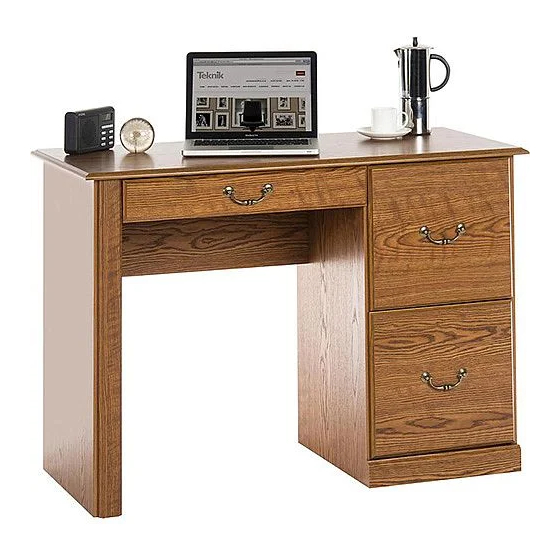
- Page 1 Teknik www.teknikoffice.co.uk Sit and surf. Computer Workcentre 5401562 NOTE: THIS INSTRUCTION BOOKLET CONTAINS IMPORTANT SAFETY INFORMATION. PLEASE READ AND KEEP FOR FUTURE REFERENCE.
- Page 2 Table of Contents Assembly Tools Required Part Identifi cation No. 2 Phillips Screwdriver Tip Shown Actual Size Hardware Identifi cation Assembly Steps 5-16 Hammer Not actual size Français 21-24 Español 25-28 Skip the power trip. Safety 29-30 This time. Warranty Part Identifi...
-
Page 3: Part Identification
Now you know Part Identifi cation our ABCs. å While not all parts are labeled, some of the parts will have a label or an inked letter on the edge to help distinguish similar parts from each other. Use this part identifi cation to help identify similar parts. D707 D707 Hardware Identifi... - Page 4 Hardware Identifi cation å Screws are shown actual size. You may receive extra hardware with your unit. EXTENSION FILE GLIDE - 4 HIDDEN CAM - 10 CAM DOWEL - 10 ANGLE BRACKET - 7 BRACKET - 2 HINGE - 2 CATCH - 1 LATCH - 1 PULL MOUNT - 6...
- Page 5 Step 1 Assemble your unit on a carpeted fl oor or on the empty å carton to avoid scratching your unit or the fl oor. Push ten HIDDEN CAMS (BB2) into the ENDS (A and B), å UPRIGHT (C), MODESTY PANEL (E), and BRACE (G). Then insert a CAM DOWEL (CC2) into each HIDDEN CAM.
- Page 6 Step 2 Fasten the CABINET RIGHTS (35GA) to the RIGHT END (A) å and a CABINET LEFTS (35GB) to the UPRIGHT (C). Use four Remember: GOLD 5/16" FLAT HEAD SCREWS (WW) through holes #1 Righty tighty. and #3. Lefty loosey. Fasten the CABINET RIGHT (35AW) to the opposite å...
- Page 7 Step 3 Fasten seven ANGLE BRACKETS (DD) to the ENDS (A å and B) and UPRIGHT (C). Use seven BLACK 9/16" LARGE HEAD SCREWS (TT). NOTE: Be sure the edges of the ANGLE BRACKETS are å even with the edges of the ENDS and UPRIGHT. Fasten the END MOLDING (Q) to the LEFT END (B).
- Page 8 Step 4 Insert a METAL PIN (NN) into the hole in the TOP (D). å Fasten the END (B) to the TOP. Tighten two HIDDEN CAMS. NOTE: Be sure the PIN in the TOP inserts into the edge of å the END.
-
Page 9: Hidden Cam
Step 5 Fasten the UPRIGHT (C) to the MODESTY PANEL (E). Use å two BLACK 1-7/8" FLAT HEAD SCREWS (OO). Insert two METAL PINS into the short edges of å the BRACE (G). Fasten the BRACE (G) to the UPRIGHT (C). Tighten one å... - Page 10 Step 6 Fasten the RIGHT END (A) to the TOP (D). Fasten two å HIDDEN CAMS. Maximum Arrow Fasten the RIGHT END (A) to the BRACE (G). Tighten the å 210 degrees HIDDEN CAM. NOTE: Be sure the PIN in the BRACE inserts into the hole Minimum å...
- Page 11 Step 7 Fasten two EXTENSION BRACKETS (EE) to the LEFT END (B). å Use four BLACK 9/16" LARGE HEAD SCREWS (TT). Fasten the CABINET LEFT (35AX) to the EXTENSION å BRACKETS (EE). Use two GOLD 5/16" FLAT HEAD SCREWS (WW) through holes #1 and #2. BLACK 9/16"...
- Page 12 Step 8 Carefully turn your unit over onto its front edges. Lay the å Caution BACK (F) over your unit. Do not stand the unit upright without the Make equal margins along all four edges of the BACK (F). Push å...
- Page 13 Step 9 Fasten the KEYBOARD SIDES (K) and KEYBOARD BACK (J) å to the KEYBOARD SHELF (H). Use four 1-1/4" FLAT HEAD SCREWS (PP). Fasten the KEYBOARD SIDES (K) to the KEYBOARD å BACK (J). Use two 1-1/4" FLAT HEAD SCREWS (PP). BLACK 1-1/4"...
- Page 14 Step 10 Fasten the CATCH (HH) to the KEYBOARD FRONT (I). å Use a 9/16" PAN HEAD SCREW (UU). To fasten the LATCH (II) to the KEYBOARD SHELF (H), insert å the BLACK 1-1/16" MACHINE SCREW (QQ) through the LATCH and KEYBOARD SHELF. Turn the BARREL NUT (JJ) onto the end of the SCREW.
- Page 15 Step 11 Fasten the DRAWER RIGHT (35AY) and the DRAWER å LEFT (35AZ) to the KEYBOARD SHELF (H). Use four Side Step: Make BROWN 1" FLAT HEAD SCREWS (RR). nachos. (Optional, but recommended.) Roller end Roller end BROWN 1" FLAT HEAD SCREW (4 used in this step) Page 15...
- Page 16 Step 12 The tabs should insert freely With the palm of your into the slots. Gently tilt the hand, tap the DRAWER DRAWER SIDES side to side BOTTOM down into until the tabs slip into the slots. the groove. fi n i s h r f a D707...
- Page 17 Step 13 Insert a SLIDE CAM (MM) into the DRAWER å SIDES (D28 and D29). Fasten a DRAWER RIGHT (35GC) to the DRAWER RIGHT å SIDE (D28) and a DRAWER LEFT (35GD) to the DRAWER LEFT SIDE (D29). Use four GOLD 5/16" FLAT HEAD SCREWS (WW) through holes #1 and #3.
- Page 18 Step 14 Fasten two PULL MOUNTS (KK) and a PULL (LL) to each å DRAWER FRONT (I and L). Use six SILVER 5/8" MACHINE SCREWS (SS). Repeat this step for the remaining drawer. å SILVER 5/8" MACHINE SCREW (6 used for the PULLS) Page 18...
- Page 19 Step 15 Carefully stand your unit upright. å If you're doing this to To insert the drawers into your unit, tip the front of the drawer å help a friend, don't down and drop the rollers on the drawer behind the rollers on leave without a bite.
- Page 20 Step 16 To make adjustments to the drawers, loosen SCREW #3 å in the SLIDES a 1/4 turn, then turn the CAM clockwise or counter-clockwise. Notice how the drawer raises or lowers as you turn the CAM. The higher the screw in the oblong hole, the higher your drawer front will be.
- Page 21 WARNING Please use your furniture correctly and safely. Improper use can cause safety hazards, or damage to your furniture or household items. Carefully read the following chart. Look out for: What can happen: How to avoid the problem: • Overloaded shelves and drawers. •...
Need help?
Do you have a question about the 5401562 and is the answer not in the manual?
Questions and answers