
Related Manuals for Teknik 5412314


Summary of Contents for Teknik 5412314
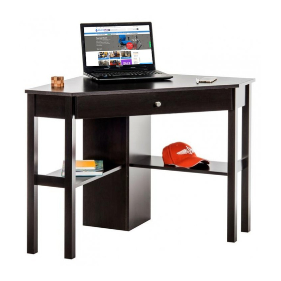
- Page 1 Teknik www.teknikoffice.co.uk Corner Computer Desk www.sa.com 5412314 Assembly Instructions NOTE THIS INSTRUCTION BOOKLET CONTAINS IMPORTANT SAFETY INFORMATION. PLEASE READ AND KEEP FOR FUTURE REFERENCE.
-
Page 2: Parts Identification
PARTS IDENTIFICATION While not all parts are labeled, some of the parts will have a label or an inked letter on the edge to help While not all parts are labeled, some of the parts will have a label or an inked letter on the edge to help distinguish similar parts from each other. -
Page 3: Hardware Identification
HARDWARE IDENTIFICATION CABINET LEFT - 1 35GA 35GB CABINET RIGHT - 1 DRAWER RIGHT - 1 DRAWER LEFT - 1 35GD 35GC HIDDEN CAM - 31 CAM SCREW - 16 CAM DOWEL - 15 HINGE - 2 KNOB - 1 CAM COVER - 4... - Page 4 SCREWS SHOWN ACTUAL SIZE SCREWS SHOWN ACTUAL SIZE Using a SCREW that is too long will caus Using a SCREW that is too long will cause e d da a mage. Before beginning assembly, separate mage. Before beginning assembly, separate each type of SCREW.
- Page 5 Do not tighten the HIDDEN CAMS in this step. Arrow Do not insert CAM DOWELS into these parts. (31 used) Arrow Arrow (15 used) Do not insert CAM DOWELS into these HIDDEN CAMS. Arrow Push thirty-one HIDDEN CAMS (U2) into the ENDS (A), UPRIGHTS (B and C), SHELVES (E), BACKS (F), DRAWER UPRIGHTS (O), and SHELF MOLDINGS (P).
- Page 6 (16 used) Turn sixteen CAM SCREWS (V2) into the LEGS (G, H, I, and J).
- Page 7 Roller End Roller End Use second hole GOLD 5/16” FLAT HEAD SCREW (4 used in this step) Fasten the CABINET RIGHT (35GA) and CABINET LEFT (35GB) to the DRAWER UPRIGHTS (O). Use four GOLD 5/16” FLAT HEAD SCREWS (GG) through holes #1 and #3.
- Page 8 Surface with HIDDEN CAMS Edge with CAM DOWELS Surface with HIDDEN CAMS Edge with CAM Surface with DOWELS HIDDEN CAMS Surface with HIDDEN CAMS Fasten the LEGS (G, H, I, and J) to the ENDS (A) and SHELF MOLDINGS (P). Tighten eight HIDDEN CAMS.
- Page 9 Surface with HIDDEN CAMS Unfi nished surface Unfi nished surface Fasten the SHELVES (E) and BACKS (F) to the LEGS (G, H, I, and J). Tighten eight HIDDEN CAMS.
- Page 10 Unfi nished surface Unfi nished Finished surface edge Fasten the LEFT UPRIGHT (C) to the RIGHT UPRIGHT (B). Tighten three HIDDEN CAMS. Caution Start Tighten Arrow Risk of damage or injury. Hidden Cams must be completely Arrow Maximum tightened. Hidden 210 degrees Cams that are not completely tightened...
- Page 11 Unfi nished surface Short unfi nished edge Maximum Arrow 210 degrees Minimum 190 degrees Fasten the UPRIGHTS (B and C) to the TOP (D). Tighten four HIDDEN CAMS.
- Page 12 BLACK 1-7/8” FLAT HEAD SCREW (8 used in this step) Maximum Arrow 210 degrees Minimum 190 degrees Fasten the SHELVES (E) and BACKS (F) to the UPRIGHTS (B and C). Use eight BLACK 1-7/8” FLAT HEAD SCREWS (AA). Fasten the ENDS (A) to the TOP (D). Tighten four HIDDEN CAMS.
- Page 13 Roller End Roller End Maximum Arrow 210 degrees Minimum 190 degrees Fasten the DRAWER UPRIGHTS (O) to the TOP (D). Tighten four HIDDEN CAMS.
- Page 14 Finished BLACK 1-1/4” FLAT HEAD SCREW surface (2 used in this step) Finished surface Long fi nished edge BROWN 1-1/2” FLAT HEAD SCREW (4 used in this step) Fasten the KEYBOARD SIDES (M) to the KEYBOARD SHELF (N). Use two BROWN 1-1/2” FLAT HEAD SCREWS (BB). ...
- Page 15 SILVER 5/8” FLAT HEAD SCREW SILVER 9/16” LARGE HEAD SCREW (2 used in this step) (4 used in this step) Fasten two HINGES (X) to the KEYBOARD FRONT (K). Use four SILVER 5/8” FLAT HEAD SCREWS (EE). Fasten the HINGES (X) to the KEYBOARD SHELF (N). Use two SILVER 9/16” LARGE HEAD SCREWS (FF).
- Page 16 Roller End Roller End BLACK 7/8” MACHINE SCREW GOLD 5/16” FLAT HEAD SCREW (1 used for the KNOB) (4 used for the SLIDES) Fasten the DRAWER RIGHT (35GC) and DRAWER LEFT (35GD) to the KEYBOARD SIDES (M). Use four GOLD 5/16” FLAT HEAD SCREWS (GG) through holes #1 and #3.
- Page 17 Carefully stand your unit upright. To insert the keyboard shelf into your unit, tip the front of the shelf down and drop the rollers on the shelf behind the rollers on the unit. Lift the front of the shelf up and slide it into the unit. ...
- Page 18 (4 used) To cover HIDDEN CAMS 20 lbs. 50 lbs. 25 lbs. 25 lbs. Push a CAM COVER (Z) onto each visible HIDDEN CAM NOTE: Please read the next two pages for important warranty and safety information. This completes assembly. Clean with your favorite furniture polish or a damp cloth. Wipe dry.
- Page 19 WARNING Please use your furniture correctly and safely. Improper use can cause safety hazards, or damage to your furniture or household items. Carefully read the following chart. Look out for: What can happen: How to avoid the problem: • Overloaded shelves and drawers. •...
Need help?
Do you have a question about the 5412314 and is the answer not in the manual?
Questions and answers