
Related Manuals for Teknik 5410416


Summary of Contents for Teknik 5410416
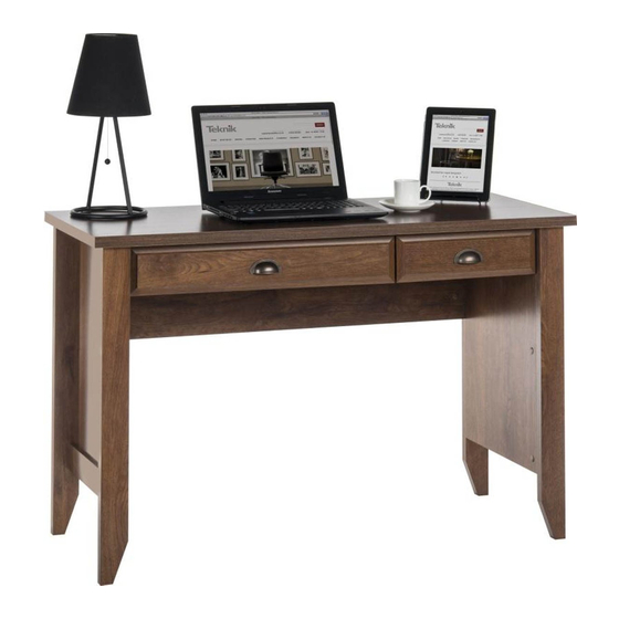
- Page 1 Teknik Sit and surf. Laptop Desk 5410416 Oiled Wood 5411204 Soft White 5409936 Jamocha Wood NOTE: THIS INSTRUCTION BOOKLET CONTAINS IMPORTANT SAFETY INFORMATION. PLEASE READ AND KEEP FOR FUTURE REFERENCE.
- Page 2 Table of Contents Assembly Tools Required Part Identifi cation No. 2 Phillips Screwdriver Tip Shown Actual Size Hardware Identifi cation Assembly Steps 6-22 Hammer Not actual size Français 23-25 Español 26-28 Skip the power trip. Safety 29-30 This time. Warranty Part Identifi...
- Page 3 Now you know Part Identifi cation our ABCs. D716 Page 3...
- Page 4 Hardware Identifi cation å Screws are shown actual size. You may receive extra hardware with your unit. 40AW CABINET RIGHT - 1 40AX CABINET LEFT - 1 40AY DRAWER RIGHT - 1 DRAWER LEFT - 1 40AZ 40CA CABINET RIGHT - 1 40CB CABINET LEFT - 1 40CC DRAWER RIGHT - 1 40CD...
- Page 5 Hardware Identifi cation å Screws are shown actual size. You may receive extra hardware with your unit. BLACK 9/16" LARGE HEAD SCREW - 6 GOLD 5/16" FLAT HEAD SCREW - 12 BROWN 1" FLAT HEAD SCREW - 4 SILVER 5/8" FLAT HEAD SCREW - 4 30S BLACK 1-9/16"...
- Page 6 Step 1 Assemble your unit on a carpeted fl oor or on the empty å carton to avoid scratching your unit or the fl oor. Push sixteen HIDDEN CAMS (1F) into the ENDS (A and B), å UPRIGHT (C), and MODESTY PANEL (E). Then, insert the metal end of six CAM DOWELS (2F) into the HIDDEN CAMS in the ENDS (A and B) and UPRIGHT (C).
- Page 7 Step 2 Turn ten CAM SCREWS (8F) into the LEGS (H, I, and J). å Remember: Fasten the FRONT LEGS (H and I) to the ENDS (A and B). å Righty tighty. Tighten six HIDDEN CAMS. Lefty loosey. (10 used) These surfaces should be even.
- Page 8 Step 3 Turn four BLACK 9/16" FLAT HEAD SCREWS (32S) into the å other surfaces of the ENDS (A and B) until the shoulders of the SCREWS rest on the surfaces of the ENDS. Slide the SIDE MOLDINGS (P) onto the ENDS (A and B). å...
- Page 9 Step 4 Turn the ENDS (A and B) over and fasten the REAR å LEGS (J) to the ENDS. Use six BLACK 2-1/4" FLAT HEAD SCREWS (26S). BLACK 2-1/4" FLAT HEAD SCREW (6 used in this step) Curved edge Page 9...
- Page 10 Step 5 Fasten the CABINET RIGHT (40CA) to the RIGHT END (A) and å CABINET LEFT (40CB) to the UPRIGHT (C). Use four GOLD 5/16" FLAT HEAD SCREWS (3S) through holes #1 and #3. Roller end GOLD 5/16" FLAT HEAD SCREW (4 used in this step) Roller end Finished edge...
- Page 11 Step 6 Fasten the CABINET LEFT (40AX) to the LEFT END (B) and å the CABINET RIGHT (40AW) to the other surface of the UPRIGHT (C). Use four GOLD 5/16" FLAT HEAD SCREWS (3S). NOTE: The CABINET RAILS are marked "CABINET RIGHT" and å...
- Page 12 Step 7 Fasten the MODESTY PANEL (E) to the ENDS (A and B). å Tighten four HIDDEN CAMS. These holes must be here. Page 12...
- Page 13 Step 8 Fasten three ANGLE BRACKETS (5G) to the å MODESTY PANEL (E). Use three BLACK 9/16" LARGE HEAD SCREWS (1S). NOTE: Be sure the edges of the ANGLE BRACKETS å are even with the edge of the MODESTY PANEL. BLACK 9/16"...
- Page 14 Step 9 Fasten the ENDS (A and B) to the TOP (D). Tighten four å HIDDEN CAMS. Then, fasten the MODESTY PANEL (E) to the TOP (D). å Use three BLACK 9/16" LARGE HEAD SCREWS (1S). BLACK 9/16" LARGE HEAD SCREW (3 used in this step) Long fi...
- Page 15 Step 10 Fasten the UPRIGHT (C) to the TOP (D). Tighten two å HIDDEN CAMS. Almost time to celebrate! With a nap. Finished edge Surface with HIDDEN CAMS Maximum Arrow 210 degrees Minimum 190 degrees Page 15...
- Page 16 Step 11 Fasten the HINGES (12H) to the KEYBOARD FRONT (G). Use four å SILVER 5/8" FLAT HEAD SCREWS (23S). Fasten the KEYBOARD HINGES (12H) to the KEYBOARD å SHELF (F). Use two SILVER 9/16" LARGE HEAD SCREWS (54S). SILVER 5/8" FLAT HEAD SCREW SILVER 9/16"...
- Page 17 Step 12 Fasten the DRAWER RIGHT (40AY) and the DRAWER å LEFT (40AZ) to the KEYBOARD SHELF (F). Use four BROWN 1" FLAT HEAD SCREWS (18S). NOTE: The DRAWER SLIDES are marked "DRAWER å RIGHT" and "DRAWER LEFT" for easy identifi cation. Fasten a PULL (27K) to the KEYBOARD FRONT (G).
- Page 18 Step 13 With the palm of your hand, The tabs should insert freely into the slots. Gently tilt the tap the DRAWER BOTTOM down into the groove. DRAWER SIDES side to side until the tabs slip into the slots. fi n i s h r f a D716...
- Page 19 Step 14 Insert a SLIDE CAM (10A) into the DRAWER SIDES (D20 and D21). å Fasten the DRAWER RIGHT (40CC) and DRAWER LEFT (40CD) å to the DRAWER SIDES (D20 and D21). Use four GOLD 5/16" FLAT HEAD SCREWS (3S) through holes #2 and #4. NOTE: The screw head in the CAM must be visible through the å...
- Page 20 Step 15 Fasten a PULL (27K) to the DRAWER FRONT (K). Use two å GOLD 1" MACHINE SCREWS (50S). GOLD 1" MACHINE SCREW (2 used for the PULL) Page 20...
- Page 21 Step 16 Carefully stand your unit upright. å Pro Tip: Lift with your To insert the drawer into your unit, tip the front of the å legs. And, you know, drawer down and drop the rollers on the drawer behind your arms.
-
Page 22: Safety
Step 17 To make adjustments to the drawer, loosen SCREW #4 in the SLIDES a 1/4 turn, then turn the CAM clockwise or å counter-clockwise. Notice how the drawer raises or lowers as you turn the CAM. The higher the screw in the oblong hole, the higher your drawer front will be. - Page 23 WARNING Please use your furniture correctly and safely. Improper use can cause safety hazards, or damage to your furniture or household items. Carefully read the following chart. Look out for: What can happen: How to avoid the problem: • Overloaded shelves and drawers. •...
Need help?
Do you have a question about the 5410416 and is the answer not in the manual?
Questions and answers