
Subscribe to Our Youtube Channel
Related Manuals for Teknik Louvre 5415109


Summary of Contents for Teknik Louvre 5415109
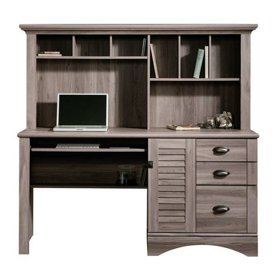
- Page 1 Teknik www.teknikoffice.co.uk For all your newfangled gadgetry. Louvre Hutch Desk Model 5415109 NOTE: THIS INSTRUCTION BOOKLET CONTAINS IMPORTANT SAFETY INFORMATION. PLEASE READ AND KEEP FOR FUTURE REFERENCE.
- Page 2 Table of Contents Assembly Tools Required Part Identifi cation No. 2 Phillips Screwdriver Tip Shown Actual Size Hardware Identifi cation Assembly Steps 6-36 Hammer Not actual size Part Identifi cation RIGHT END (1) BOTTOM (1) RIGHT TOP MOLDING (1) LEFT END (1) DOOR (1) LEFT TOP MOLDING (1) RIGHT HUTCH END (1)
- Page 3 Part Identifi cation å While not all parts are labeled, some of the parts will have a label or an inked letter on the edge to help distinguish similar parts from each other. Use this part identifi cation to help identify similar parts. D708 D109 D716...
- Page 4 Hardware Identifi cation å Screws are shown actual size. You may receive extra hardware with your unit. EXTENSION RAIL - 2 EXTENSION SLIDE - 2 35AW CABINET RIGHT - 1 35AX CABINET LEFT - 1 (EXTENSION SET SHOWN SEPARATED) 35AY DRAWER RIGHT - 1 40CA CABINET RIGHT - 2 35AZ DRAWER LEFT - 1 40CB CABINET LEFT - 2...
-
Page 5: Table Of Contents
Hardware Identifi cation å Screws are shown actual size. You may receive extra hardware with your unit. FELT DISC CARD - 1 CORD CLIP - 1 HOLE PLUG - 4 NAIL - 73 3R LONG METAL PIN - 1 RUBBER SLEEVE - 4 METAL PIN - 21 BLACK 9/16"... - Page 6 Step 1 Assemble your unit on a carpeted fl oor or on the empty å carton to avoid scratching your unit or the fl oor. To begin assembly, push a SAUDER TWIST-LOCK® å FASTENER (10F) into the large holes in the ENDS (A and B).
- Page 7 Step 2 Slide the HUTCH END MOLDINGS (Y) onto the notched å edges of the HUTCH ENDS (C and D) until the ends are even. Some assembly Slide the DESK END MOLDING (X) onto the notched edge (and snacks) required. å...
-
Page 8: Black 9/16" Large Head Screw
Step 3 Fasten the EXTENSION BRACKETS (45G) to the LEFT END (B). å Use four BLACK 9/16” LARGE HEAD SCREWS (1S). Fasten an ANGLE BRACKET (27G) to the LEFT END (B) and å DESK END MOLDING (X). Use two BLACK 9/16" LARGE HEAD SCREWS (1S). -
Page 9: Gold 5/16" Flat Head Screw
Step 4 Fasten the CABINET RIGHT (35AW) to the LEFT å UPRIGHT (F) and a CABINET LEFT (35AX) to the LEFT END (B). Use four GOLD 5/16" FLAT HEAD SCREWS (3S). Roller end Roller end GOLD 5/16" FLAT HEAD SCREW (4 used in this step) Page 9... - Page 10 Step 5 Fasten the CABINET RIGHTS (40CA) to the RIGHT å END (A) and CABINET LEFTS (40CB) to the RIGHT UPRIGHT (E). Use eight GOLD 5/16" FLAT HEAD SCREWS (3S) through holes #1 and #3. Roller end Edge with TWIST-LOCK® FASTENERS Finished edge Roller end Finished edge...
- Page 11 Step 6 Separate the EXTENSION SLIDES (EE) from the å EXTENSION RAILS (DD) as shown in the upper diagram below. Be prepared, the parts are greasy. Fasten the EXTENSION RAILS (DD) to the RIGHT END (A) å and RIGHT UPRIGHT (E). Use four GOLD 5/16" FLAT HEAD SCREWS (3S).
- Page 12 Step 7 Tap two MOLDING CONNECTORS (18F) into the notches å in the MOLDINGS (Z, AA, and BB). Use your hammer to tap the MOLDING CONNECTORS (18F) into the notches in the MOLDINGS. Flat end Flat end Page 12...
- Page 13 Step 8 Fasten the TOP MOLDINGS (Z, AA and BB) to the TOP (I). å Use eight BLACK 1-5/8" PAN HEAD SCREWS (27S). Just think. The sooner you do this, the sooner NOTE: Do not overtighten the SCREWS into the TOP. å...
- Page 14 Step 9 Fasten the HUTCH LEFT END (D) to the LEFT TOP å Caution MOLDING (BB). Tighten two TWIST-LOCK® FASTENERS. Do not stand the unit upright without the Insert eight METAL PINS (1R) into the SMALL å BACK fastened. The unit may collapse. PINNED UPRIGHTS (T).
- Page 15 Step 10 Fasten the HUTCH LONG SHELF (L) to the HUTCH LEFT å END (D). Tighten two TWIST-LOCK® FASTENERS. NOTE: Be sure the PINS in SMALL PINNED UPRIGHTS (T) å insert into the holes in the HUTCH LONG SHELF (L). Finished edge S u r f a c...
- Page 16 Step 11 Fasten the HUTCH UPRIGHT (G) to the HUTCH TOP (I) and HUTCH å LONG SHELF (L). Tighten four TWIST-LOCK® FASTENERS. Insert eight METAL PINS (1R) into the LARGE PINNED UPRIGHTS (S). å Push the METAL PINS in the edges of the LARGE PINNED UPRIGHTS å...
- Page 17 Step 12 Fasten the HUTCH SHELF (M) to the HUTCH å UPRIGHT (G). Tighten two TWIST-LOCK® FASTENERS. NOTE: Be sure the PINS in LARGE PINNED UPRIGHTS (S) å insert into the holes in the HUTCH SHELF (M). Fasten the HUTCH RIGHT END (C) to the RIGHT TOP å...
-
Page 18: Black 2-1/4" Flat Head Screw
Step 13 Insert four HOLE PLUGS (14P) into the holes in the å TOP MOLDING (Z). Fasten the DESK TOP (H2) to the HUTCH LEFT END (D), å HUTCH UPRIGHT (G), and HUTCH RIGHT END (C). Use six BLACK 2-1/4" FLAT HEAD SCREWS (26S). Meet Part (H2). - Page 19 Step 14 Push the LONG METAL PIN (3R) into the DESK TOP (H2). å Now might be a Fasten the LEFT END (B) to the DESK TOP (H2). Tighten å good time to refresh two TWIST-LOCK® FASTENERS. your drink. NOTE: Be sure the LONG METAL PIN (3R) inserts into the å...
-
Page 20: Black 1-7/8" Flat Head Screw
Step 15 Fasten the SHELF (K) to the MODESTY PANEL (J). Use å Edge with TWIST-LOCK® FASTENERS three BLACK 1-7/8" FLAT HEAD SCREWS (2S). Push a METAL PIN (1R) into the hole in the short edge of å the SHELF (K). NOTE: You may want to use packaging material to prop å... - Page 21 Step 16 Fasten the LEFT UPRIGHT (F) to the DESK TOP (H2). å Tighten two TWIST-LOCK® FASTENERS. Fasten the LEFT UPRIGHT (F) to the SHELF (K) and å MODESTY PANEL (J). Use four BLACK 1-7/8" FLAT HEAD SCREWS (2S). ® - L O I S T i t h...
- Page 22 Step 17 Fasten the RIGHT UPRIGHT (E) to the DESK TOP (H2). å Tighten two TWIST-LOCK® FASTENERS. Fasten the BOTTOM (N) to the LEFT UPRIGHT (F). Tighten å two TWIST-LOCK® FASTENERS. Fasten the BOTTOM (N) to the RIGHT UPRIGHT (E). Use å...
- Page 23 Step 18 Fasten the RIGHT END (A) to the DESK TOP (H2). Tighten å two TWIST-LOCK® FASTENERS. Fasten the RIGHT END (A) to the BOTTOM (N). Tighten å two TWIST-LOCK® FASTENERS. Page 23...
- Page 24 Step 19 Fasten four ANGLE BRACKETS (27G) to the BOTTOM (N), å RIGHT END (A), and LEFT UPRIGHT (F). Use four BLACK 9/16" LARGE HEAD SCREWS (1S). NOTE: Be sure the BRACKETS are even with the edges of å the BOTTOM, RIGHT END, and LEFT UPRIGHT. Fasten the BASE (CC) to the ANGLE BRACKETS (27G) on å...
- Page 25 Caution Step 20 Do not stand the unit upright without the BACK fastened. The unit may collapse. Carefully turn your unit over onto its front edges. Unfold the LARGE BACK (P) and lay it over your unit. å Make equal margins along all four edges of the LARGE BACK (P). Push on opposite corners of your unit if needed to make å...
-
Page 26: Black 1/2" Flat Head Screw
Step 21 Fasten the HINGES (40H) to the DOOR (O). Use four å BLACK 1/2" FLAT HEAD SCREWS (11S). BLACK 1/2" FLAT HEAD SCREW (4 used in this step) Page 26... - Page 27 Step 22 Carefully stand your unit upright. å Pro Tip: Lift with your Before fastening the DOOR to your unit, be sure the å legs. And, you know, mounting screw is against the stops as shown in the right your arms. diagram.
- Page 28 Step 23 Refer to the enlarged diagram to identify the parts on the HINGES. å The DOORS may need some adjustments. Follow the text below to å make needed adjustments. DOOR ADJUSTMENTS: å To adjust the DOORS from side to side (horizontal), turn the adjusting screw in or out.
- Page 29 Step 24 The tabs should insert freely With the palm of your hand, into the slots. Gently tilt the tap the DRAWER BOTTOM DRAWER SIDES side to side down into the groove. until the tabs slip into the slots. fi n i s h r f a D708...
- Page 30 Step 25 Insert a SLIDE CAM (10A) into the DRAWER SIDES (D88 and D87). å Fasten the EXTENSION SLIDES (EE) to the DRAWER SIDES (D87 å and D88). Use four GOLD 5/16" FLAT HEAD SCREWS (3S) through holes #1 and #4. NOTE: The screw head in the CAM must be visible through the å...
- Page 31 Step 26 Insert a SLIDE CAM (10A) into the DRAWER SIDES (D24 and D25). å Fasten the DRAWER RIGHT (40CC) and DRAWER LEFT (40CD) å to the DRAWER SIDES (D24 and D25). Use four GOLD 5/16" FLAT HEAD SCREWS (3S) through holes #2 and #4. NOTE: The screw head in the CAM must be visible through the å...
- Page 32 Step 27 Fasten a PULL (98K) to the DRAWER FRONT (V). Use two å SILVER 5/8" MACHINE SCREWS (15S). Repeat fastening a PULL (98K) to the other drawers. å SILVER 5/8" MACHINE SCREW (6 used for the PULLS) Page 32...
- Page 33 Step 28 Push a FILE GLIDE (6B) onto the LARGE RIGHT å DRAWER SIDE (D87). Slide the FILE RODS (8B) into the FILE GLIDE (6B) on å the LARGE RIGHT DRAWER SIDE (D87). Slide another FILE GLIDE (6B) onto the other end of the å...
- Page 34 Step 29 Fasten the DRAWER RIGHT (35AY) and the DRAWER å LEFT (35AZ) to the KEYBOARD SHELF (U). Use four Almost time to BROWN 1" FLAT HEAD SCREWS (18S). celebrate! With a nap. Push a CORD CLIP (4P) into the hole in the å...
- Page 35 Step 30 To insert the small drawers into your unit, tip the front of the drawer down and drop the rollers on the drawer å behind the rollers on the unit. Lift the front of the drawer up and slide it into the unit. Repeat this step to insert the KEYBOARD SHELF (U).
- Page 36 Step 31 To make adjustments to the drawers, loosen SCREW #4 in the SLIDES a 1/4 turn, then turn the CAM clockwise or å counter-clockwise. Notice how the drawer raises or lowers as you turn the CAM. The higher the screw in the oblong hole, the higher your drawer front will be.
- Page 37 WARNING Please use your furniture correctly and safely. Improper use can cause safety hazards, or damage to your furniture or household items. Carefully read the following chart. Look out for: What can happen: How to avoid the problem: • Overloaded shelves and drawers. •...
Need help?
Do you have a question about the Louvre 5415109 and is the answer not in the manual?
Questions and answers