Advertisement
Quick Links
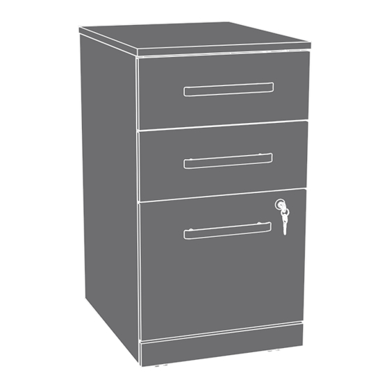
3-Drawer Mobile
Pedestal
Hudson Elm finish | Model 5427873
Teknik
www.teknikoffice.co.uk
NOTE: THIS INSTRUCTION
BOOKLET CONTAINS
IMPORTANT SAFETY
INFORMATION.
PLEASE READ AND KEEP
FOR FUTURE REFERENCE.
English pg 1-28
Français pg 29-32
Español pg 33-36
Lot # 572777
Purchased:
__________________
10/13/21
Advertisement

Related Manuals for Teknik 5427873


Summary of Contents for Teknik 5427873
- Page 1 3-Drawer Mobile NOTE: THIS INSTRUCTION Pedestal BOOKLET CONTAINS IMPORTANT SAFETY INFORMATION. PLEASE READ AND KEEP Hudson Elm finish | Model 5427873 FOR FUTURE REFERENCE. English pg 1-28 Français pg 29-32 Español pg 33-36 Lot # 572777 10/13/21 Purchased: __________________...
- Page 2 Table of Contents Assembly Tools Required Part Identification No. 2 Phillips Screwdriver Hardware Identification Tip Shown Actual Size Hardware Usage Guide Assembly Steps 6-28 Hammer Not actual size Français 29-32 Español 33-36 Safety 37-38 Adjustable Wrench Warranty Page 2...
- Page 3 Now you know Part Identification our ABCs. å While not all parts are labeled, some of the parts will have a label or an inked letter on the edge to help distinguish similar parts from each other. Use this part identification to help identify similar parts. RIGHT END (1) D579 RIGHT DRAWER SIDE (2) BOTTOM (1)
- Page 4 Hardware Identification å Screws are shown actual size. You may receive extra hardware with your unit. 40CA CABINET RIGHT - 2 40CB CABINET LEFT - 2 40CC DRAWER RIGHT - 2 40CD DRAWER LEFT - 2 (EXTENSION SET SHOWN SEPARATED) EXTENSION EXTENSION SLIDE...
- Page 5 Hardware Identification å Screws are shown actual size. You may receive extra hardware with your unit. Z - LOCK 21J LOCK PACK - 1 10M TOUCH-UP PEN - 1 202K PULL - 3 BRACKET - 1 3S GOLD 5/16" FLAT HEAD SCREW - 24 BLACK 9/16"...
- Page 6 Hardware Usage Guide HOW TO USE A TWIST-LOCK FASTENER ® Push a TWIST-LOCK® FASTENER into the large hole in the part. 1. Insert the dowel end of the FASTENER into the hole of the adjoining part. NOTE: The dowel end of the FASTENER must remain fully inserted in the hole of the adjoining part while locking the FASTENER.
- Page 7 Step 1 å Assemble your unit on a carpeted floor or on the empty carton to avoid scratching your unit or the floor. Some assembly å Insert two WOOD DOWELS (42F) into the BACK (D). (and snacks) required. å NOTE: You may need to gently tap the WOOD DOWEL in with your hammer.
- Page 8 Step 2 å Fasten two CABINET RIGHTS (40CA) to the RIGHT END (A). Use four GOLD 5/16" FLAT HEAD SCREWS (3S) through holes #1 and #3. Roller end GOLD 5/16" FLAT HEAD SCREW (4 used in this step) These holes must be here.
- Page 9 Step 3 å Separate the EXTENSION SLIDES (40MC) from the EXTENSION RAILS (40MA) as shown in the upper diagram below. Be prepared, the parts are greasy. å Fasten one EXTENSION RAIL (40MA) to the RIGHT END (A). Use two GOLD 5/16" FLAT HEAD SCREWS (3S) through holes #1 and #4.
- Page 10 Step 4 å Fasten the INTERLOCK MECHANISM (34G) to the RIGHT END (A). Use three BLACK 9/16" PAN HEAD SCREWS (51S). å Fasten the L-LOCK BRACKET (76G) to the RIGHT END (A) exactly as shown. Use two BLACK 9/16" LARGE HEAD SCREWS (1S). BLACK 9/16"...
- Page 11 Step 5 å Insert four WOOD DOWELS (42F) into the RIGHT END (A). å NOTE: You may need to gently tap the WOOD DOWEL in with your hammer. å Fasten the BACK (D) and BOTTOM (E) to the RIGHT END (A). Tighten four TWIST-LOCK® FASTENERS. å...
- Page 12 Step 6 å Fasten two CABINET LEFTS (40CB) to the LEFT END (B). Use four GOLD 5/16" FLAT HEAD SCREWS (3S) through holes #1 and #3. GOLD 5/16" FLAT HEAD SCREW (4 used in this step) Edge with TWIST-LOCK® FASTENERS Roller end Page 12...
- Page 13 Step 7 å Fasten the remaining EXTENSION RAIL (40MA) to the LEFT END (B). Use two GOLD 5/16" FLAT HEAD SCREWS (3S) through holes #1 and #4. å NOTE: For each EXTENSION RAIL, turn a SCREW into the hole shown in the enlarged diagram. Then, slide the inner cartridge of the EXTENSION RAIL in to find the other hole that lines up with the hole in the END.
- Page 14 Step 8 å Insert four WOOD DOWELS (42F) into the LEFT END (B). å NOTE: You may need to gently tap the WOOD DOWEL in with your hammer. å Fasten the LEFT END (B) to the BACK (D) and BOTTOM (E). Tighten four TWIST-LOCK® FASTENERS. å...
- Page 15 Step 9 å Insert six WOOD DOWELS (42F) into the TOP (C). Just think. The sooner å NOTE: You may need to gently tap the WOOD DOWEL in you do this, the sooner with your hammer. you do something else. å...
- Page 16 Step 10 å Fasten four METAL BRACKETS (4G) to the ENDS (A and B) and BOTTOM (E). Use four BLACK 9/16" LARGE HEAD SCREWS (1S). BLACK 9/16" LARGE HEAD SCREW å NOTE: Be sure the BRACKETS are even with the edges of (8 used in this step) the ENDS and BOTTOM.
- Page 17 Step 11 å Fasten the CASTERS (8CN and 8CS) to the BOTTOM (E) exactly as shown. Use sixteen BLACK 9/16" LARGE HEAD SCREWS (1S). BLACK 9/16" LARGE HEAD SCREW (16 used in this step) The small tab should be here. Page 17...
- Page 18 Step 12 The tabs should insert freely into the slots. Gently tilt the DRAWER SIDES side to side until the tabs slip into the slots. BLACK 9/16" LARGE HEAD SCREW (2 used in this step) D579 D580 Groove å å Fasten the Z-LOCK BRACKET (77G) to one of the Insert the DRAWER SIDES (D579 and D580) at an angle DRAWER FRONTS (G).
- Page 19 Step 13 å Insert a SLIDE CAM (10A) into each DRAWER SIDE (D579 and D580). å Fasten the DRAWER RIGHT (40CC) to the RIGHT DRAWER SIDE (D579) and the DRAWER LEFT (40CD) to the LEFT DRAWER SIDE (D580). Use four GOLD 5/16" FLAT HEAD SCREWS (3S) through holes #2 and #4. å...
- Page 20 Step 14 The tabs should insert freely With the palm of into the slots. Gently tilt the your hand, tap DRAWER SIDES side to side the DRAWER U n fi until the tabs slip into the slots. BOTTOM down n i s h s u r f a c into the groove.
- Page 21 Step 15 å Insert a SLIDE CAM (10A) into each LARGE DRAWER SIDE (D581 and D582). å Fasten two EXTENSION SLIDES (40MC) to the LARGE DRAWER SIDES (D581 and D582). Use four GOLD 5/16" FLAT HEAD SCREWS (3S) through holes #1 and #4. å...
- Page 22 Step 16 å Fasten one PULL (202K) to the LOCKING DRAWER FRONT (H). Use two BLACK 7/8" MACHINE SCREWS (37S). å Fasten one PULL (202K) to one of the DRAWER FRONTS (G). Use two BLACK 7/8" MACHINE SCREWS (37S). å Repeat this step for the remaining small DRAWER.
- Page 23 Step 17 å Fasten one DRAWER ACTUATOR (62G) to the LARGE RIGHT DRAWER SIDE (D581) of the LOCKING DRAWER FRONT (H) exactly as shown. Use three BLACK 1/2" FLAT HEAD SCREWS (11S). This DRAWER ACTUATOR å Fasten one DRAWER ACTUATOR (62G) to the RIGHT DRAWER is closer to hole in the SIDE (D579) of the DRAWER FRONT (G) with the Z-LOCK BRACKET.
- Page 24 Step 18 å Push a FILE GLIDE (15B) onto the LARGE RIGHT DRAWER SIDE (D581). Almost time to å Slide the FILE RODS (8B) into the FILE GLIDE (15B) on celebrate! With a nap. the LARGE RIGHT DRAWER SIDE. å Slide another FILE GLIDE (15B) onto the other end of the FILE RODS (8B), then press this FILE GLIDE over the LARGE LEFT DRAWER SIDE (D582).
- Page 25 Step 19 å Fasten the LOCK PACK (21J) to the LOCKING DRAWER FRONT (H) in the exact order shown. å NOTE: It is important to position the CAM exactly as shown. å NOTE: Turn the KEY to the right to lock. WASHER SCREW The prongs must press...
- Page 26 Step 20 å Carefully stand your unit upright. å Diagram 1 - Pull the lower wing of the INTERLOCK MECHANISM (34G) forward until it clicks into place. å Diagram 2 - To insert the LOCKING DRAWER (H) into your unit, line up the EXTENSION SLIDES on the drawer with the EXTENSION RAILS on the unit and push the drawer into the unit until it is fully inserted.
- Page 27 Step 21 å To make adjustments to the drawer, loosen SCREW #4 in the SLIDES a 1/4 turn, then turn the cam clockwise or counter-clockwise. Notice how the drawer raises or lowers as you turn the cam. By adjusting the drawer this way, it will help the DRAWER FRONT line up better when closed.
- Page 28 Step 22 å For long-term care and maintenance of your unit, you may touch up the edges with the TOUCH-UP PEN (10M). å NOTE: Please read the back pages of the instruction booklet for important safety information. å This completes assembly. Clean with a damp cloth. Wipe dry. 7 lbs.
Need help?
Do you have a question about the 5427873 and is the answer not in the manual?
Questions and answers