
Related Manuals for Teknik 5427030


Summary of Contents for Teknik 5427030
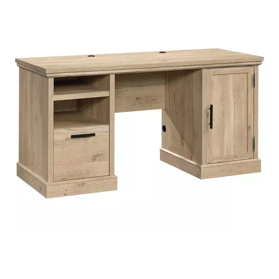
- Page 1 Teknik For all your newfangled gadgetry. Prime Oak Computer Desk NOTE: THIS INSTRUCTION BOOKLET CONTAINS IMPORTANT SAFETY INFORMATION. Model 5427030 PLEASE READ AND KEEP FOR FUTURE REFERENCE.
- Page 2 Table of Contents Assembly Tools Required Part Identification No. 2 Phillips Screwdriver Hardware Identification Tip Shown Actual Size Hardware Usage Guide Assembly Steps 6-37 Hammer Not actual size Français 38-42 Español 43-47 Safety 48-50 Tape Measure Warranty Now you know Part Identification our ABCs.
- Page 3 Part Identification D708 Page 3...
- Page 4 Hardware Identification å Screws are shown actual size. You may receive extra hardware with your unit. (EXTENSION SET SHOWN SEPARATED) EXTENSION RAIL - 2 EXTENSION SLIDE - 2 40MA 40MC 10A SLIDE CAM - 2 FILE GLIDE - 2 TWIST-LOCK MOLDING WOOD ®...
- Page 5 Hardware Identification å Screws are shown actual size. You may receive extra hardware with your unit. BLACK 9/16" LARGE HEAD SCREW - 72 3S GOLD 5/16" FLAT HEAD SCREW - 8 BLACK 1/2" FLAT HEAD SCREW - 1 BLACK 2-1/4" FLAT HEAD SCREW - 4 30S BLACK 1-9/16"...
- Page 6 Step 1 å Assemble your unit on a carpeted floor or on the empty carton to avoid scratching your unit or the floor. Just think. The sooner you do this, the sooner å Push four CORD CLIPS (4P) into the holes in the TOP (N). you do something else.
- Page 7 Step 2 å Tap two MOLDING CONNECTORS (17F) into the notches in the MOLDINGS (L, M, and P). Use your hammer to tap the MOLDING CONNECTORS (17F) into the notches in the MOLDINGS. Unfinished surface Flat end Flat end Page 7...
- Page 8 Step 3 å Carefully flip the MOLDINGS (L, M and P) over, and fasten them to the TOP (N). Use eight BROWN 1-5/8" FLAT HEAD SCREWS (55S). å NOTE: Start each SCREW a few turns before completely tightening any of them. å...
- Page 9 Hardware Usage Guide HOW TO USE A TWIST-LOCK FASTENER ® 1. Insert the dowel end of the FASTENER into the Push a TWIST-LOCK® FASTENER hole of the adjoining part. into the large hole in the part. NOTE: The dowel end of the FASTENER must remain fully inserted in the hole of the adjoining part while locking the FASTENER.
- Page 10 Step 5 å Fasten the MODESTY PANEL (F) to the TOP (N). Tighten two TWIST-LOCK® FASTENERS. S u r f a c i t h I S T - L O ® F A S T E N E R Page 10...
- Page 11 Step 6 å Push four SAUDER TWIST-LOCK® FASTENERS (37F) into the large holes in the LEFT END (B) and LEFT UPRIGHT (R). å Insert four WOOD DOWELS (15F) into the LEFT END (B) and LEFT UPRIGHT (R). Do not tighten the TWIST-LOCK® FASTENERS in this step. Groove Meet Parts (B and R).
- Page 12 Step 7 å Separate the EXTENSION SLIDES (40MC) from the EXTENSION RAILS (40MA) as shown in the upper diagram below. Be prepared, the parts are greasy. å Fasten the EXTENSION RAILS (40MA) to the LEFT END (B) and LEFT UPRIGHT (R). Use four GOLD 5/16"...
- Page 13 Step 8 å Fasten the LEFT UPRIGHT (R) to the TOP (N). Tighten two TWIST-LOCK® FASTENERS. å NOTE: Be sure the WOOD DOWELS in the LEFT UPRIGHT insert into the TOP. å Fasten the LEFT UPRIGHT (R) to the MODESTY PANEL (F). Use two BLACK 2-1/4"...
- Page 14 Step 9 å Push four SAUDER TWIST-LOCK® FASTENERS (37F) into the large holes in the FIXED SHELF (K). å Fasten the FIXED SHELF (K) to the LEFT UPRIGHT (R). Tighten two TWIST-LOCK® FASTENERS. Finished edge Page 14...
- Page 15 Step 10 å Fasten the LEFT END (B) to the FIXED SHELF (K) and TOP (N). Tighten four TWIST-LOCK® FASTENERS. å NOTE: Be sure the WOOD DOWELS in the LEFT END insert into the LEFT TOP MOLDING. Groove Page 15...
- Page 16 Step 11 å Push four SAUDER TWIST-LOCK® FASTENERS (37F) into the large holes in the RIGHT END (A) and RIGHT UPRIGHT (S). å Insert four WOOD DOWELS (15F) into the RIGHT END (A) and RIGHT UPRIGHT (S). Do not tighten the TWIST-LOCK® FASTENERS in this step. Groove Parts (A) and (S).
- Page 17 Step 12 å Fasten the RIGHT UPRIGHT (S) to the TOP (N). Tighten two TWIST-LOCK® FASTENERS. å NOTE: Be sure the WOOD DOWELS in the RIGHT UPRIGHT insert into the TOP. å Fasten the RIGHT UPRIGHT (S) to the MODESTY PANEL (F). Use two BLACK 2-1/4"...
- Page 18 Step 13 å Fasten the RIGHT END (A) to the TOP (N). Tighten two TWIST-LOCK® FASTENERS. å NOTE: Be sure the WOOD DOWELS in the RIGHT END insert into the TOP. å Slide the BACKS (O) into the grooves of the ENDS (A and B) and UPRIGHTS (R and S).
- Page 19 Step 14 å Fasten the BOTTOMS (H) to the ENDS (A and B) and UPRIGHTS (R and S). Use eight BLACK 1-15/16" FLAT Remember: HEAD SCREWS (113S). Righty tighty. Lefty loosey. å NOTE: Start each SCREW a few turns before completely tightening any of them.
- Page 20 Step 15 å Fasten eight CORNER BRACKETS (31G) to the BOTTOMS (H) exactly as shown. Use sixteen BLACK 9/16" LARGE HEAD SCREWS (1S). BLACK 9/16" LARGE HEAD SCREW (16 used in this step) Page 20...
- Page 21 Step 16 å Fasten two METAL BRACKETS (4G) to a pair of SKIRTS (C and D). Use two BLACK 9/16" LARGE HEAD SCREWS (1S). å NOTE: Be sure the BRACKETS are even with the edges of the SKIRTS. å Repeat this step for the remaining SKIRTS. BLACK 9/16"...
- Page 22 Step 17 å Fasten the LARGE SKIRTS (D) to the CORNER BRACKETS on the BOTTOMS (H). Use sixteen BLACK 9/16" LARGE HEAD SCREWS (1S). å Fasten the LARGE SKIRTS (D) to the BOTTOMS (H). Use four BLACK 9/16" LARGE HEAD SCREWS (1S) through the METAL BRACKETS on the SKIRTS and into the holes in the BOTTOMS.
- Page 23 Step 18 å Fasten the SMALL SKIRTS (C) to the CORNER BRACKETS on the BOTTOMS (H). Use sixteen BLACK 9/16" LARGE HEAD SCREWS (1S). å Fasten the SMALL SKIRTS (C) to the BOTTOMS (H). Use four BLACK 9/16" LARGE HEAD SCREWS (1S) through the METAL BRACKETS on the SKIRTS and into the holes in the BOTTOMS.
- Page 24 Step 19 Optional Hidden Wireless Qi Compatible Charger by Eggtronic (sold separately) å This piece of furniture accommodates an optional Hidden Wireless Qi Compatible Charger by Eggtronic (Item 425905) for charging your smartphone. Eliminate the clutter and inconvenience of a charging cable. Charge your phone by simply setting it on top of your furniture.
- Page 25 Step 20 Optional Hidden Wireless Qi Compatible Charger by Eggtronic (sold separately) WARNING å Insert the HIDDEN WIRELESS Qi COMPATIBLE CHARGER by EGGTRONIC Please use the wireless charging port into one of the large holes in the TOP (N). correctly and safely. Improper use can cause safety hazards, or damage to your furniture or household items.
- Page 26 Step 21 å Slide the SHELF MOLDING* (Q) onto the notched edge of the UPPER ADJUSTABLE SHELF (J). å *U.S. Patent No. 5,499,886 Slide the SHELF MOLDING (Q) onto the notched edge. These surfaces should be even. The groove is closer to this edge.
- Page 27 Step 22 å Carefully stand your unit upright. å Insert two GROMMETS (10P) and two GROMMET CAPS (1P) into the large holes in the TOP (N). å Insert a GROMMET (10P) and GROMMET CAP (1P) into the RIGHT UPRIGHT (S). å...
- Page 28 Step 23 å Fasten the HINGES (31G) to the DOOR (T). Use four BLACK 9/16" LARGE HEAD SCREWS (1S). å NOTE: The HINGES will wrap around the top corner of the DOOR. å Fasten the STRIKE PLATE (6I) to the DOOR (T). Use the BLACK 1/2"...
- Page 29 Step 24 å Fasten the DOOR (T) to the RIGHT END (A). Use four BLACK 9/16" LARGE HEAD SCREWS (1S). å Fasten a PULL (191K) to the DOOR (T). Use two BLACK 7/8" MACHINE SCREWS (37S). BLACK 9/16" LARGE HEAD SCREW (4 used for the HINGES) 191K BLACK 7/8"...
- Page 30 Step 25 With the palm of The tabs should insert freely your hand, tap into the slots. Gently tilt the the DRAWER DRAWER SIDES side to side BOTTOM down until the tabs slip into the slots. U n fi n i s h into the groove.
- Page 31 Step 26 å Insert a SLIDE CAM (10A) into the DRAWER SIDES (D87 and D88). å Fasten the EXTENSION SLIDES (40MC) to the DRAWER SIDES (D87 and D88). Use four GOLD 5/16" FLAT HEAD SCREWS (3S) through holes #1 and #4. å...
- Page 32 Step 27 å Push a FILE GLIDE (6B) onto the RIGHT DRAWER SIDE (D87). å Slide the FILE RODS (8B) into the FILE GLIDE (6B) on the RIGHT DRAWER SIDE (D87). å Slide another FILE GLIDE (6B) onto the other end of the FILE RODS (8B), then press this FILE GLIDE over the LEFT DRAWER SIDE (D88).
- Page 33 Step 28 å To insert the drawer into your unit, line up the EXTENSION SLIDES on the drawer with the EXTENSION RAILS on the If you're doing this to unit and push the drawer into the unit until the drawer is fully help a friend, don't inserted.
- Page 34 Step 29 Optional Hidden Wireless Qi Compatible Charger by Eggtronic (sold separately) å IMPORTANT: The WIRELESS CHARGING SPOT STICKER must be placed directly above the CHARGER. å First, measure in from both edges of the TOP above your CHARGER as shown. Then, make a slight mark where the two measurements intersect.
- Page 35 Step 30 å To make adjustments to the drawer, loosen SCREW #4 in the SLIDES a 1/4 turn, then turn the cam clockwise or counter-clockwise. Notice how the drawer raises or lowers as you turn the cam. By adjusting the drawer this way, it will help the DRAWER FRONT line up better when closed.
- Page 36 Step 31 å NOTE: Turn the MAGNETIC CATCH in or out so the STRIKE PLATE on the DOOR connects with it when the DOOR is closed. å NOTE: Please read the back pages of the instruction booklet for important safety information. å...
- Page 37 WARNING Please use your furniture correctly and safely. Improper use can cause safety hazards, or damage to your furniture or household items. Carefully read the following chart. Look out for: What can happen: How to avoid the problem: • Overloaded shelves or drawers. •...
Need help?
Do you have a question about the 5427030 and is the answer not in the manual?
Questions and answers