
Subscribe to Our Youtube Channel
Related Manuals for Teknik 5402174


Summary of Contents for Teknik 5402174
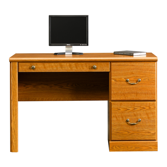
- Page 1 Teknik www.teknikoffice.co.uk For all your newfangled gadgetry. Traditional Computer Workcentre Model 5402174...
- Page 2 Table of Contents Assembly Tools Required Part Identifi cation No. 2 Phillips Screwdriver Tip Shown Actual Size Hardware Identifi cation Assembly Steps 7-24 Hammer Not actual size Safety 33-34 Warranty Page 2...
- Page 3 Part Identifi cation å While not all parts are labeled, some of the parts will have a label or an inked letter on the edge to help distinguish similar parts from each other. Use this part identifi cation to help identify similar parts. RIGHT END (1) DRAWER BACK (1) KEYBOARD FRONT (1)
- Page 4 Hardware Identifi cation LONG RIGHT CABINET RAIL - 1 LONG LEFT CABINET RAIL - 1 LONG RIGHT DRAWER SLIDE - 1 35AW CABINET RIGHT - 1 35AX CABINET LEFT - 1 LONG LEFT DRAWER SLIDE -1 35AY DRAWER RIGHT - 1 35AZ DRAWER LEFT - 1 FILE ROD - 2 EXTENSION BRACKET - 2...
- Page 5 Hardware Identifi cation å Screws are shown actual size. You may receive extra hardware with your unit. 30S BLACK 1-9/16" FLAT HEAD SCREW - 4 BLACK 1-7/8" FLAT HEAD SCREW - 2 BROWN 1" FLAT HEAD SCREW - 4 SILVER 1-1/8" FLAT HEAD SCREW - 4 SILVER 3/4"...
- Page 6 Step 1 Assemble your unit on a carpeted fl oor or on the empty å carton to avoid scratching your unit or the fl oor. Push twelve HIDDEN CAMS (1F) into the ENDS (A å and B2), UPRIGHT (C), MODESTY PANEL (E), and SHELF (F).
- Page 7 Step Step 2 Fasten three ANGLE BRACKETS (NN) to the LEFT END (B2). å Use three GOLD 9/16" LARGE HEAD SCREWS (AAA). Remember: Righty tighty. Fasten the END MOLDING (R) to the ANGLE BRACKETS (NN). å Lefty loosey. Use three GOLD 9/16" LARGE HEAD SCREWS (AAA). NOTE: There are no pre-drilled holes in the END å...
- Page 8 Step Step 3 Fasten two EXTENSION BRACKETS (DD) to the LEFT END (B2). å Use four GOLD 9/16" LARGE HEAD SCREWS (AAA). Fasten the CABINET RIGHT (35AW) to the UPRIGHT (C) å and the CABINET LEFT (35AX) to the LEFT END (B2). Use four GOLD 5/16"...
-
Page 9: Part Identifi Cation
Step Step 4 Fasten the LONG RIGHT CABINET RAIL (T) to the RIGHT å END (A) and the LONG LEFT CABINET RAIL (U) to the opposite surface of the UPRIGHT (C). Use four GOLD 5/16" FLAT HEAD SCREWS (CCC). NOTE: The CABINET RAILS are marked "CABINET å... - Page 10 Step Step 5 Turn two CAM SCREWS (8F) into the LEFT END (B2). å Fasten the TOP MOLDING (Q) to the TOP (D). Use four SILVER 1-1/8" å FLAT HEAD SCREWS (UU). NOTE: Do not overtighten the SCREWS. å Insert a METAL PIN (QQ) into the hole in the TOP (D). å...
- Page 11 Step Step 6 Fasten the MODESTY PANEL (E) to the LEFT END (B2). å Caution Tighten two HIDDEN CAMS. Do not stand the unit upright without the Fasten the UPRIGHT (C) to the TOP (D). Tighten two å BACK fastened. The unit may collapse. HIDDEN CAMS.
- Page 12 Step Step 7 Fasten the SHELF (F) to the UPRIGHT (C). Tighten two å HIDDEN CAMS. Maximum Arrow 210 degrees Insert a METAL PIN (QQ) into the hole in the TOP (D). å Fasten the RIGHT END (A) to the TOP (D) and SHELF (F). Minimum å...
- Page 13 Step 8 Fasten nine ANGLE BRACKETS (NN) to the BRACES (J). å Use nine GOLD 9/16" LARGE HEAD SCREWS (AAA). NOTE: Be sure the edges of the ANGLE BRACKETS are å even with the edges of the BRACES (J). Carefully turn your unit over onto its front edges. å...
- Page 14 Step 9 Fasten the BASE MOLDING (S) to the RIGHT END (A), å UPRIGHT (C), and BRACE (J). Use three GOLD 9/16" LARGE HEAD SCREWS (AAA). GOLD 9/16" LARGE HEAD SCREW (3 used in this step) Page 14...
- Page 15 Step 10 Lay the BACK (G) over your unit. å Caution Make equal margins along all four edges of the BACK (G). Push å Do not stand the unit upright without the on opposite corners of your unit if needed to make it "square". BACK fastened.
- Page 16 Step Step 11 Fasten two HINGES (HH) and HINGE SPACERS (JJ) to the å DOOR (K). Use four SILVER 5/8" FLAT HEAD SCREWS (ZZ). Carefully stand your unit upright. å Before fastening the DOOR to your unit, be sure the å...
- Page 17 Step Step 12 Refer to the enlarged diagram to identify the parts on å the HINGES. The DOORS may need some adjustments. Follow the text å below to make needed adjustments. Mounting screw (depth) Adjusting screw (horizontal) DOOR ADJUSTMENTS: å To adjust the DOORS from side to side (horizontal) turn the adjusting screw in or out.
- Page 18 Step Step 13 Fasten the KEYBOARD HINGES (12H) to the KEYBOARD å FRONT (I2). Use four SILVER 5/8" FLAT HEAD SCREWS (ZZ). Fasten the KEYBOARD HINGES to the KEYBOARD SHELF (H2). å Use two SILVER 9/16" LARGE HEAD SCREWS (BBB). Push a DOOR STOP (4I) into the hole in the å...
- Page 19 Step Step 14 Fasten the DRAWER RIGHT (35AY) and DRAWER LEFT (35AZ) å to the KEYBOARD SHELF (H2). Use four BROWN 1" FLAT HEAD SCREWS (VV). Fasten the PULLS (MM) to the KEYBOARD FRONT (I2). å Use two SILVER 7/8" MACHINE SCREWS (WW). Push a CORD CLIP (PP) into the hole in the å...
-
Page 20: Black 1-9/16" Flat Head Screw
Step Step 15 The tabs should insert freely With the palm of your hand, into the slots. Gently tilt the tap the DRAWER BOTTOM DRAWER SIDES side to side down into the groove. until the tabs slip into the slots. fi... - Page 21 Step 16 Insert a SLIDE CAM (RR) into each DRAWER å SIDE (D28 and D29). Fasten the LONG RIGHT DRAWER SLIDE (V) to the å RIGHT DRAWER SIDE (D28) and the LONG LEFT DRAWER SLIDE (W) to the LEFT DRAWER SIDE (D29). Use four GOLD 5/16"...
- Page 22 Step 17 Push a FILE GLIDE (15B) onto the RIGHT DRAWER SIDE (D28). å Slide the FILE RODS (CC) into the FILE GLIDE (15B) on å the RIGHT DRAWER SIDE. Almost time to Slide another FILE GLIDE (15B) onto the other end of the å...
- Page 23 Step 18 To insert the drawer into your unit, tip the front of the å drawer down and drop the rollers on the drawer behind the rollers on the unit. Lift the front of the drawer up and slide it into the unit. Repeat this step to insert the KEYBOARD SHELF (H2).
- Page 24 Step 19 To make adjustments to the drawers, loosen SCREW #3 in the SLIDES a 1/4 turn, then turn the å CAM clockwise or counter-clockwise. Notice how the drawer raises or lowers as you turn the CAM. The higher the screw in the oblong hole, the higher your drawer front will be. The lower the screw, the lower the drawer front.
- Page 25 WARNING Please use your furniture correctly and safely. Improper use can cause safety hazards, or damage to your furniture or household items. Carefully read the following chart. Look out for: What can happen: How to avoid the problem: • Overloaded shelves and drawers. •...
Need help?
Do you have a question about the 5402174 and is the answer not in the manual?
Questions and answers