Advertisement
Quick Links
Advertisement

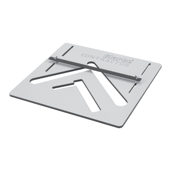
Summary of Contents for Clarke CONTRACTOR CSJ100
- Page 1 STAIR JIG STAIR JIG Model No: CSJ100 Part No: 6462120 OPERATION & MAINTENANCE INSTRUCTIONS 0405...
- Page 2 Please note that the details and specifications contained herein, are correct at the time of going to print. However, CLARKE International reserve the right to change specifications at any time without prior notice.
- Page 3 CLARKE GUARANTEE This CLARKE product is guaranteed against faulty manufacture for a period of 12 months from the date of purchase. Please keep your receipt as proof of purchase.
- Page 4 Other equipment required for use with this jig Hand Router capable of taking a 22mm dovetail cutter + standard 30mm guide bush. Minimum of 2 ‘G’ clamps. For closed staircase:- 16mm cutter for 22mm & 25.4mm treads. 22mm cutter for 28.1mm & 32mm treads. 95º...
- Page 5 Going The going of a step is the space between the nosing of one step and the nosing of the step above - or as British Standards state, face of a riser to face of a riser. Like the riser, British Standards state strict regulations.
- Page 6 As stated earlier in the Rise of step terminology, the going should be no less than 220 for a private Example - 185mm stairway or 250mm for a common stairway. Let us Going of presume that the going (G) is step 240mm.
- Page 7 Measure from the right angled line along the side of the string, the going length and mark this point. From the same corner point intersection, measure Pitch Angle Line Rise across the end along the right angled line, the rise, and mark this point. Now draw a line between these two points.
- Page 8 NOSE 22.0mm 25.4mm 28.1mm 32.0mm TREAD Ø16mm Cutter Ø16mm Cutter 22.0mm 10mm Offset 10mm Offset Bush 2 Bush 1 Ø16mm Cutter Ø16mm Cutter 25.4mm 8mm Offset 8mm Offset Bush 3 Bush 4 Ø22mm Cutter Ø22mm Cutter 28.1mm 7mm Offset 7mm Offset Bush 2 Bush 1 Ø22mm Cutter...
- Page 9 13. Attach the correct nosing bush and cutter size to the router, set the plunge depth to 12mm (refer to tabIe on page 7 for correct guide bush and Cutter). The edge of bush has to be flat with inside edge of jig to ensure correct nosing and gap thickness for tread.
- Page 10 NOTE: Enough room has to be left on the string before the first riser is cut to ensure there is no break-out. It is better to have more material, than not enough as the strings can be cut to size afterwards. 16.
- Page 11 Follow the same procedure as in points 1 — 3 on page 5, making sure that the margin is set at 44mm. Calculate the rise with the going to make sure it complies with approved document K. As there is an overlap of 15mm on the tread, the going is set at 245mm as opposed to 260mm.


Need help?
Do you have a question about the CONTRACTOR CSJ100 and is the answer not in the manual?
Questions and answers