
Related Manuals for Clarke CONTRACTOR CWJ700


Summary of Contents for Clarke CONTRACTOR CWJ700
- Page 1 WORKTOP JIG WORKTOP JIG Model No: CWJ700/CWJ900 Part No: 6462118/6462119 OPERATION & MAINTENANCE INSTRUCTIONS 0305...
- Page 2 Please note that the details and specifications contained herein, are correct at the time of going to print. However, CLARKE International reserve the right to change specifications at any time without prior notice.
- Page 3 CLARKE GUARANTEE This CLARKE product is guaranteed against faulty manufacture for a period of 12 months from the date of purchase. Please keep your receipt as proof of purchase.
- Page 4 Safety Precautions WARNING: As with all machinery, there are certain hazards involved with their operation and use. Exercising respect and caution will considerably reduce the risk of personal injury. However, if normal safety precautions are overlooked or ignored, personal injury to the operator or damage to property, may result. 1.
- Page 5 Using The Jig Front View Fig. 1 Rear View Fig. 2 Before Starting: ALWAYS ensure the worktop is firmly supported on trestles or similar. ensure the jig is firmly secured to the worktop using no less than 2 quick woodworking clamps or similar. ensure there are no obstructions in the path of the router, also the router cutter beneath the worktop, i.e.
- Page 6 Standard Joints 90º Left 90º Right Corner joint Hand Joint Hand Joint using left right 45º joints 45º Right 45º Left Hand Joint Hand Joint Fig. 3 Before commencing, prepare the router by removing the fence guide etc if fitted, attach the 30mm guide bush and if available, a dust extractor, also install the cutter.
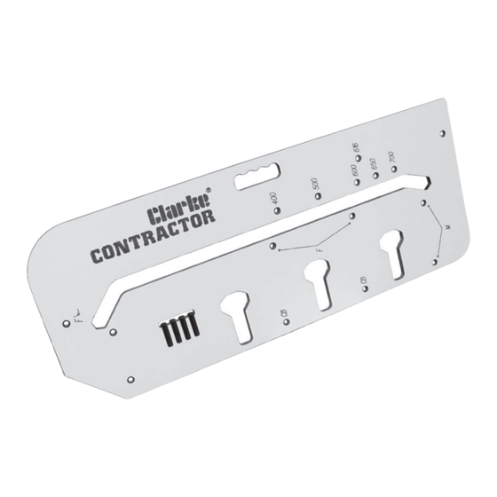
- Page 7 4. Ensure the 3 pins in holes ‘F’ are pushed firmly against the post formed edge, and the fourth pin in the hole marked with the worktop width is pushed firmly against the worktop edge. 5. Firmly clamp the jig onto the worktop ensuring the clamps do not obstruct the router path.
- Page 8 Female Bolt Recesses (Fig. 6) - Place the worktop with the laminate face down. 17. Fully insert three pins in holes marked ‘CB’. 18. Clamp the jig to the worktop ensuring the three pins are firmly pushed up to the cut out face and the worktop edge.
- Page 9 24. Place the router into the front of one of the clamp bolt recesses, set the depth of cut to 10mm max. Switch the router ON and machine the recess. When done, switch the router OFF and wait for the cutter to stop spinning. Return the router to the back again.
- Page 10 11. Firmly clamp the jig to the worktop ensuring it doesn’t move as you do so. Ensure the clamps do not obstruct the router path. Cut Direction Post Form Edge Pencil Line Fig. 9 Male Joint - Laminate face up. Cutting - follow steps 6 - 9 on page 6.
- Page 11 Male Bolt Recesses (Fig. 11) - Place the worktop with laminate face down. 19. Fully insert 3 pins in the holes marked ‘CB’. 20. Clamp the jig to the worktop ensuring all 3 pins are pushed firmly against the worktop. Ensure clamps do not obstruct the router path. Male bolt recesses - Post Form Edge Laminate face down.
- Page 12 772mm Fig. 13 Pencil Line Post Form Edge Cut Direction Position the jig onto the worktop to be cut into the male piece, referring back to the instructions for cutting 90º joints. Subtract 228mm from the intended length, e.g. 1000mm - 228mm = 772mm. Position the worktop jig 772mm from the opposite end of the worktop you are cutting.
- Page 13 Female joint - laminate face up. Fig. 15 Post Form Edge Cut Direction 4. Ensure the 2 pins in holes ‘F’ are pushed firmly against the post form edge of the worktop, clamp the jig to the worktop ensuring clamps do not obstruct the router path.
- Page 14 Cut Direction Post Form Edge Pencil Line Fig. 17 Male Joint - Laminate face down. 11. Firmly clamp the jig to the worktop ensuring it doesn’t move as you do so. Ensure the clamps do not obstruct the router path. Cutting - Follow steps 6 - 9 on page 6.
- Page 15 Male Bolt Recesses (Fig. 19) - Place the worktop with laminate face down. 19. Fully insert 3 pins in the holes marked ‘CB’. 20. Clamp the jig to the worktop ensuring all 3 pins are pushed firmly against the worktop. Ensure clamps do not obstruct the router path. Post Form Edge Male bolt recesses - Fig.
- Page 16 Female joint - laminate face down. Post Form Edge Cut Direction Fig. 20 Male Joint (Fig. 21) - Place the worktop with the laminate face up. 8. Fully insert two pins in the jig holes marked ‘M’ with angle symbol 9.
- Page 17 Fig. 22 Female bolt recesses - Laminate face down. Post Form Edge Female Bolt Recesses (Fig. 18) - Place the worktop with the laminate face down. 14. Fully insert three pins in holes marked ‘CB’. 15. Clamp the jig to the worktop ensuring the three pins are firmly pushed up to the cut out face and the worktop edge.
- Page 18 19. Fully insert 3 pins in the holes marked ‘CB’. 20. Clamp the jig to the worktop ensuring all 3 pins are pushed firmly against the worktop. Ensure clamps do not obstruct the router path. 21. Place the router into the front of one of the clamp bolt recesses, set the depth of cut to 10mm max.
-
Page 19: Health And Safety
Polishing with a propriety anti-static household polish, can aid the movement of the router across the surface of the jig. In case of loss, replacement pegs are available from your Clarke dealer. Part No: WTJIG-01-PEGS-BK HEALTH AND SAFETY...
Need help?
Do you have a question about the CONTRACTOR CWJ700 and is the answer not in the manual?
Questions and answers