Table of Contents
Advertisement
Advertisement
Table of Contents

Related Manuals for Clarke CSB20B


Summary of Contents for Clarke CSB20B
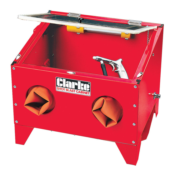
- Page 1 SHOT BLAST CABINET MODEL NO: CSB20B PART NO: 7640110 USER INSTRUCTIONS GC0216...
- Page 2 INTRODUCTION Thank you for purchasing this CLARKE Shot Blast Cabinet which is designed for professional workshop use. Before attempting to operate the cabinet, please read this manual thoroughly and carefully follow all instructions given. In doing so you will ensure the safety of yourself and that of others around you, and you can also look forward to the product giving you long and satisfactory service.
- Page 3 INVENTORY Remove all components from the carton and check them against the following list. A - Foam Vent Filter B - Air Vent Cover C - 9 x Spare protective film D - Ceramic Nozzles 4, 5, 6 & 7mm (one nozzle is fitted) E - PTFE tape F - Gun c/w air and pickup hoses G - 12V transformer &...
-
Page 4: Safety Precautions
Thread a flat washer, followed by the extended nut, onto the adapter, from the outside of the cabinet, and tighten. Insert the circular foam filter into the recess in the Air Vent Cover, and attach the cover to the rear of the cabinet as shown in Fig 3, having first prised out the plastic bung from the vent hole. -
Page 5: Operation
• Do not use any silica based abrasives with this cabinet. Silica based abrasives have been linked to severe respiratory disease. Always use recommended abrasives. Abrasives used in this unit may be covered by COSHH Regulations. OPERATION Plug the transformer into the power supply and switch the power ON. Switch the lamp ON by pushing the rocker switch on the switch box ‘I’. -
Page 6: Replacing The Abrasive Nozzle
• Should any abrasive be spilled, ensure it is cleaned up immediately, as its slippery properties can be hazardous. REPLACING THE ABRASIVE NOZZLE Ensure the air supply is disconnected before performing this operation. 1. Pull the trigger of the gun as a precautionary measure. 2. -
Page 7: Changing The Fluorescent Tube
Re-fit the assembly into its retaining clips and test its operation by plugging the transformer into the mains. GUARANTEE This CLARKE product is guaranteed against faulty manufacture for a period of 12 months from the date of purchase. Please keep your receipt as proof of purchase. -
Page 8: Troubleshooting
TROUBLESHOOTING Problem Check Solution Excessive dust in the No dust extract device Install dust extract cabinet. used. device. Air vent or overflow Clean rear vent and blocked. keep vent away from any wall. Abrasive media worn. Replace abrasive media Too much abrasive media in Remove excessive the cabinet. -
Page 9: Declaration Of Conformity
DECLARATION OF CONFORMITY Parts & Service: 020 8988 7400 / E-mail: Parts@clarkeinternational.com or Service@clarkeinternational.com... -
Page 10: Parts List
PARTS LIST PART NO DESCRIPTION PART NO DESCRIPTION Steel Screen Feet Fluorescent Tube Cabinet only (no lid) Input Cable Assembly Air Adaptor Nut Knob Lid Retaining Chain Filter Abrasive Pick-up Tube Retaining Disc Abrasive Intake Hose Large Hose Clamp Window Retaining Strip Nozzle Adaptor Nut Protective Film Nozzle (4mm) -
Page 11: Parts Diagram
PARTS DIAGRAM Parts & Service: 020 8988 7400 / E-mail: Parts@clarkeinternational.com or Service@clarkeinternational.com...
Need help?
Do you have a question about the CSB20B and is the answer not in the manual?
Questions and answers